EP4115708B1 - Dimmbare spiral-led-filamentanordnung und lampe - Google Patents
Dimmbare spiral-led-filamentanordnung und lampe Download PDFInfo
- Publication number
- EP4115708B1 EP4115708B1 EP21706581.2A EP21706581A EP4115708B1 EP 4115708 B1 EP4115708 B1 EP 4115708B1 EP 21706581 A EP21706581 A EP 21706581A EP 4115708 B1 EP4115708 B1 EP 4115708B1
- Authority
- EP
- European Patent Office
- Prior art keywords
- led
- led filament
- filaments
- luminous flux
- filament
- Prior art date
- Legal status (The legal status is an assumption and is not a legal conclusion. Google has not performed a legal analysis and makes no representation as to the accuracy of the status listed.)
- Active
Links
Images


Classifications
-
- H—ELECTRICITY
- H05—ELECTRIC TECHNIQUES NOT OTHERWISE PROVIDED FOR
- H05B—ELECTRIC HEATING; ELECTRIC LIGHT SOURCES NOT OTHERWISE PROVIDED FOR; CIRCUIT ARRANGEMENTS FOR ELECTRIC LIGHT SOURCES, IN GENERAL
- H05B45/00—Circuit arrangements for operating light-emitting diodes [LED]
- H05B45/10—Controlling the intensity of the light
-
- F—MECHANICAL ENGINEERING; LIGHTING; HEATING; WEAPONS; BLASTING
- F21—LIGHTING
- F21K—NON-ELECTRIC LIGHT SOURCES USING LUMINESCENCE; LIGHT SOURCES USING ELECTROCHEMILUMINESCENCE; LIGHT SOURCES USING CHARGES OF COMBUSTIBLE MATERIAL; LIGHT SOURCES USING SEMICONDUCTOR DEVICES AS LIGHT-GENERATING ELEMENTS; LIGHT SOURCES NOT OTHERWISE PROVIDED FOR
- F21K9/00—Light sources using semiconductor devices as light-generating elements, e.g. using light-emitting diodes [LED] or lasers
- F21K9/20—Light sources comprising attachment means
- F21K9/23—Retrofit light sources for lighting devices with a single fitting for each light source, e.g. for substitution of incandescent lamps with bayonet or threaded fittings
- F21K9/232—Retrofit light sources for lighting devices with a single fitting for each light source, e.g. for substitution of incandescent lamps with bayonet or threaded fittings specially adapted for generating an essentially omnidirectional light distribution, e.g. with a glass bulb
-
- F—MECHANICAL ENGINEERING; LIGHTING; HEATING; WEAPONS; BLASTING
- F21—LIGHTING
- F21Y—INDEXING SCHEME ASSOCIATED WITH SUBCLASSES F21K, F21L, F21S and F21V, RELATING TO THE FORM OR THE KIND OF THE LIGHT SOURCES OR OF THE COLOUR OF THE LIGHT EMITTED
- F21Y2115/00—Light-generating elements of semiconductor light sources
- F21Y2115/10—Light-emitting diodes [LED]
-
- Y—GENERAL TAGGING OF NEW TECHNOLOGICAL DEVELOPMENTS; GENERAL TAGGING OF CROSS-SECTIONAL TECHNOLOGIES SPANNING OVER SEVERAL SECTIONS OF THE IPC; TECHNICAL SUBJECTS COVERED BY FORMER USPC CROSS-REFERENCE ART COLLECTIONS [XRACs] AND DIGESTS
- Y02—TECHNOLOGIES OR APPLICATIONS FOR MITIGATION OR ADAPTATION AGAINST CLIMATE CHANGE
- Y02B—CLIMATE CHANGE MITIGATION TECHNOLOGIES RELATED TO BUILDINGS, e.g. HOUSING, HOUSE APPLIANCES OR RELATED END-USER APPLICATIONS
- Y02B20/00—Energy efficient lighting technologies, e.g. halogen lamps or gas discharge lamps
- Y02B20/30—Semiconductor lamps, e.g. solid state lamps [SSL] light emitting diodes [LED] or organic LED [OLED]
Definitions
- the present disclosure relates generally to the field of solid-state lighting. Specifically, it relates to a LED filament arrangement and a LED filament lamp.
- Incandescent lamps are rapidly being replaced by LED-based lighting solutions. It is nevertheless appreciated and desired by users to have retrofit lamps which have the look of an incandescent bulb.
- Solid-state lighting devices may provide many advantages over their incandescent, fluorescent, and gas-discharge based counterparts. For instance, they may provide increased operational life, reduced power consumption and higher efficacy. Solid-state lighting devices, such as LEDs, are employed in a wide range of lighting applications.
- a light bulb in CN 209672092 a light bulb is disclosed that includes a bulb housing, a heat sink, and a head housing arranged in series along a longitudinal axis of the light bulb.
- the light bulb includes a first filament having a first LED chip capable of emitting a first light with a first color characteristic, and a second filament having a second LED chip capable of emitting a second light with a second color characteristic.
- the first filament and the second filament are spiral along a transverse axis perpendicular to the longitudinal axis of the light bulb.
- the light bulb further includes a driving module configured to enable one or a combination of the first filament and the second filament to emit light.
- One general aim of the present disclosure is to provide low-cost dimmable LED filament systems with a pleasant appearance.
- a light-emitting diode (LED) filament system comprises a LED filament arrangement including a plurality of LED filaments.
- the plurality of LED filaments is interwound around a common central axis, such that each of the LED filaments has (forms) a spiral-shape. Neighboring LED filaments differ by a translation pitch along the common central axis.
- the LED filament system further comprises a controller.
- the controller is configured to control power supply to the LED filaments such that at least one of the plurality of LED filaments is individually controllable. Further, the controller is configured to control the power supply to the LED filaments in a first mode, in which all the LED filaments are in an on-state, and the controller provides power supply above a first power level to the LED filaments. The controller is further configured to control the power supply to the LED filaments in a second mode, in which at least one of the LED filaments are in an off-state.
- the positions of the different LED filaments within the LED filament arrangement do not coincide. Rather, the respective arrangements of the LED filaments may differ by a translation along the central axis and/or a rotation around the central axis.
- the translation pitch is the distance between two neighboring LED filaments of the LED filament arrangement in a direction along the central axis.
- the controller may, through controlling the power supply to the LED filaments, control the luminous flux of the LED filament arrangement. Controlling a light source to provide a luminous flux lower than a maximum luminous flux may be referred to as dimming the light source. The ability to dim light sources is highly appreciated by users.
- the present LED filament system may provide a dimmable lighting solution at a low cost.
- the LED filament arrangement may, for a given translation pitch (t), provide a light distribution corresponding in the first mode to a uniform light-emitting surface, and in the second mode to at least one light-emitting spiral.
- the controller may control the LED filament arrangement (in a first mode) such that all LED filaments are illuminated (in an on-state, emitting light).
- the arrangement of the LED filaments may provide the LED filament arrangement with an appearance that the light originated from a (single) light-emitting surface or a volumetric light source.
- the arrangement of the LED filaments may, when all LED filaments of the LED filament arrangement are illuminated and when they emit light above a certain intensity (corresponding to a first power level provided by the controller), provide an appearance that the light originates from a single tubular/cylindrical light-emitting surface.
- the controller may also control the LED filament arrangement (in a second mode) such that at least one LED filament is not illuminated (in an off-state, not emitting light), which may provide the LED filament arrangement with an appearance of one or more spiral LED filaments.
- the translation pitch (t) may be in a range from 1 to 5 times the width (w) of one of the LED filaments (i.e. 1 w ⁇ t ⁇ 5 w ).
- the translation pitch may be in a range from 2 to 4.5 times the width (i.e. 2 w ⁇ t ⁇ 4.5 w ). More specifically, the translation pitch may be in a range from 3 to 4 times the width (i.e. 3 w ⁇ t ⁇ 4 w ).
- the translation pitch may be in the range 2.5-12.5 mm. Specifically, in embodiments in which the width of a LED filament is 2.5 mm, the translation pitch may be in the range 5-11.25 mm. More specifically, in embodiments in which the width of a LED filament is 2.5 mm, the translation pitch may be in the range 7.5-10 mm.
- a translation pitch according to the present embodiments may provide a balance between improved thermal management and the provision of an appearance of a continuous light-emitting surface when all LED filaments are illuminated.
- each of the LED filaments may be arranged in a spiral-shape having a substantially constant spiral pitch.
- the spiral pitch may be the distance between successive loops of the spiral-shape.
- Embodiments in which each LED filament is arranged in a spiral-shape having a substantially constant spiral pitch may provide a more uniform light distribution and a more pleasant appearance.
- the spiral pitch may differ by less than 20%. Specifically, the spiral pitch may differ by less than 10%. More specifically, the spiral pitch may differ by less than 5%.
- the spiral pitch (p) may be in a range from 8 times the width (w) of a LED filament to 20 times the width (w) (i.e. 8 w ⁇ p ⁇ 20 w ).
- the spiral pitch may be in a range from 10 to 19 times the width (i.e. 10 w ⁇ p ⁇ 19 w ). Specifically, the spiral pitch may be in a range from 12 to 18 times the width (i.e. 12 w ⁇ p ⁇ 18 w ). More specifically, the spiral pitch may be in a range from 14 to 16 times the width (i.e. 14 w ⁇ p ⁇ 16 w ).
- the spiral pitch may be in the range 20-50 mm. Specifically, if the width of a LED filament is 2.5 mm, the spiral pitch may be in the range 22.5-45 mm. More specifically, when the width of a LED filament is 2.5 mm, the spiral pitch may be in the range 25-37.5 mm.
- the width (w) of a LED filament may be in a range from 1 to 4 mm.
- the width may be in a range from 1.8 to 3.5 mm. More specifically, the width may be in a range from 2 to 3 mm.
- the PAR may be in a range from 2 to 8.
- the PAR may be in a range from 3 to 6. More specifically, the PAR may be in a range from 4 to 5.
- the controller may be configured to receive an input signal which represents a desired luminous flux.
- the controller may further be configured to select, based on the desired luminous flux, at least one LED filament to which to provide power. Further, the controller may be configured to select a power level of the at least one LED filament to provide the desired luminous flux, and to provide power in accordance with the selected power level to the at least one selected LED filament.
- Individual (or group) powering of the LED filaments may provide dimming solutions in which, for a desired total luminous flux of the LED filament arrangement, a subset of the LED filaments may be illuminated to provide a higher flux level instead of all LED filaments being illuminated to provide a same, lower flux level.
- Such dimming solutions may be more efficient than conventional dimming, as the LED filaments may be operated closer to their optimal efficiency.
- the controller may be configured to provide power supply to only one LED filament if the desired luminous flux is below a first limit.
- One LED filament being illuminated, and the rest being turned off, may give the LED filament arrangement the appearance of a single LED filament.
- using one LED filament may provide the most pleasant appearance and illumination.
- the controller may be configured to provide power supply to all LED filaments if the desired luminous flux is above a second limit.
- all the LED filaments may be illuminated.
- illuminating all LED filaments may provide the appearance of a continuous cylinder-shaped light source.
- a light-emitting surface may provide the most pleasant look and illumination.
- the controller may be further configured to provide power to the first LED filament corresponding to the maximum flux level.
- the controller may further be configured to provide power to a second LED filament to achieve the desired luminous flux.
- the first LED filament may be powered.
- the first LED filament may be powered at the highest level, and a second LED filament may be powered to reach the desired luminous flux.
- the desired luminous flux exceeds the combined maximum luminous flux level of the first and the second LED filament, the first and the second LED filaments may be powered at the highest level, and a third LED filament may be powered such that the LED filament arrangement may reach the desired luminous flux.
- the controller may be further configured to provide power to the first LED filament and at least one second LED filament at equal levels.
- a first LED filament may be powered. If the desired luminous flux exceeds the maximum luminous flux level of the first LED filament, both the first LED filament and a second LED filament may be powered at equal (same) levels, such that the LED filament arrangement may provide the desired luminous flux. If the desired luminous flux exceeds the combined maximum luminous flux of the first LED filament and the second LED filament, the first LED filament, the second LED filament and a third LED filament may be powered at equal levels such that the LED filament arrangement may provide the desired luminous flux.
- Providing even power levels to the illuminated LED filaments may provide a more uniform illumination. Further, such a solution may provide that the LED filaments are more evenly used and more evenly worn, which may lead to a longer operational life for the LED filament system.
- the controller may be configured to provide power to the first LED filament at a first level, the first level being lower than the maximum flux level and provide power to a second LED filament at a second level lower than the first level. If the desired luminous flux is above the second threshold, the controller may be configured to provide power to the first LED filament and the second LED filament at equal levels (or at least substantially equal levels).
- a first LED filament may be powered. If the input increases to correspond to luminous flux levels above the maximum luminous flux one single LED filament, the power supply to the first LED filament may be gradually decreased simultaneously with a more rapid gradual increase in the power supplied to a second LED filament. For a certain input level, corresponding to the second threshold, the first LED filament and the second LED filament may be powered at equal levels (or at least substantially equal power levels). For inputs corresponding to flux levels above the second threshold, the first LED filament and the second LED filament may be equally powered.
- Gradual lowering of the power supply of the first LED filament combined with an increase of the power supply of the second LED filament, may provide a smoother transition between powering of one LED filament and two LED filaments. Similar control may be applied for transitions between e.g. three and four LED filaments, four and five LED filaments etc.
- each of the LED filaments may be arranged in a spiral-shape having a substantially constant radius.
- the distance from the LED filament to the central axis may be substantially constant.
- LED filaments in accordance with these embodiments may form a cylindrical coil or a helical shape.
- the radius of the spiral-shape may differ by less than 20%. Specifically, the radius of the spiral-shape may differ by less than 10%. More specifically, the radius of the spiral-shape may differ by less than 5%.
- the radius of the spiral-shape may be in the range 1-10 cm. Specifically, the radius of the spiral-shape may be in the range 2-8 cm. More specifically, the radius of the spiral-shape may be in the range 3-6 cm.
- the LED filament arrangement may comprise 2 to 8 LED filaments.
- the LED filament arrangement may comprise 3 to 7 LED filaments. Specifically, the LED filament arrangement may comprise 3 to 5 LED filaments. More specifically, the LED filament arrangement may comprise four LED filaments. Four LED filaments in the LED filament arrangement may form a quadruple helix.
- the LED filaments may be substantially identical in shape and size.
- the LED filaments may have substantially the same width.
- the LED filaments may have substantially the same length.
- the LED filaments may have substantially the same diameter.
- the LED filaments may provide light with substantially the same color temperature.
- the LED filaments may provide light with substantially the same color rendering index (CRI).
- the size of the LED filaments may differ by less than 20%. Specifically, the size of the LED filaments may differ by less than 10%. More specifically, the size of the LED filaments may differ by less than 5%.
- the shape of the LED filaments may differ by less than 20%. Specifically, the shape of the LED filaments may differ by less than 10%. More specifically, the shape of the LED filaments may differ by less than 5%.
- a lighting device may comprise a LED filament system as described above in any of the embodiments of the first aspect of the present disclosure.
- the lighting device may further comprise an at least partially light-transmissive envelope.
- the envelope may envelop at least the plurality of LED filaments of the LED filament system.
- the lighting device may further comprise a base on which the envelope may be mounted. The base may be adapted to be connected with a luminaire socket.
- the controller of the LED filament system may be at least partly arranged within the base of the lighting device. Alternatively, or additionally, the controller of the LED filament system may be at least partly arranged within the envelope of the lighting device.
- the LED filament system comprises a plurality of LED filaments 110a-c, and a controller 120.
- the plurality of LED filaments 110a-c comprises three LED filaments: a first LED filament 110a, a second LED filament 110b, and a third LED filament 110c.
- the description applies to each of the LED filaments 110a-c.
- the suffix a-c will be used.
- the LED filaments 110 are each arranged forming a spiral-shape. More specifically, the LED filaments 110 each form a helix winding around a central axis A.
- the helix-shapes each have a (substantially) constant radius r.
- the radius r is the shortest distance from a point of the LED filament 110 to the central axis A.
- each of the helix-shapes have a (substantially) constant spiral pitch p.
- the spiral pitch p is the length of a loop of the helix-shape of the LED filament 110 in the direction of the central axis. In other words, it is distance between a starting point of a loop, and a starting point of the successive loop.
- the LED filaments 110 each have a width w, and their spiral- (helix-) shapes have a height h.
- the LED filaments 110 are substantially identical in shape and size.
- the LED filaments 110a-c are arranged around the common central axis A. In other words, the LED filaments 110a-c are coaxial. The positions of the LED filaments 110a-c differ by a rotation around the central axis, such that two neighboring LED filaments 110 differ by a translation pitch t along the central axis A.
- the translation pitch t between the first LED filament 110a and the second LED filament 110b is illustrated. However, the translation pitch between each pair of successive LED filaments 110 may be (substantially) equal.
- the LED filament arrangement 105 comprises three LED filaments 110.
- the width w of the LED filaments 110 may be 2.5 mm.
- the LED filament arrangement may comprise four LED filaments.
- the width (w 2 ) of the LED filaments may be 2 mm.
- the PAR may be four.
- the LED filament arrangement may comprise five LED filaments.
- the width (w 3 ) of the LED filaments may be 3 mm.
- the PAR may be five.
- the LEDs may be arranged on at least one of these surfaces.
- the carrier may be reflective or light transmissive, such as translucent and preferably transparent.
- the LED filament may comprise an encapsulant at least partly covering at least part of the plurality of LEDs.
- the encapsulant may also at least partly cover at least one of the first major or second major surface.
- the encapsulant may be a polymer material which may be flexible such as for example a silicone. Further, the LEDs may be arranged for emitting LED light e.g. of different colors or spectrums.
- the encapsulant may comprise a luminescent material that is configured to at least partly convert LED light into converted light.
- the luminescent material may be a phosphor such as an inorganic phosphor and/or quantum dots or rods.
- the LED filament may comprise multiple sub-filaments.
- the controller 120 of the LED filament system 100 is configured to control the power supply to the LED filaments 110a-c. Specifically, the controller 120 is configured to control the power supply to each one of the LED filaments 1 10a-c via the electrical connections 121.
- the controller may be configured to control the LED filament arrangement according to at least two operating modes depending on a received input.
- a first operating mode the controller may be configured to operate the LED filament arrangement such that only one LED filament is turned on.
- the lighting device would resemble a lamp having a spiral-shaped filament.
- a second operating mode the controller may be configured to operate the LED filament arrangement such that all LED filaments are turned on. In this second operating mode, the lighting device would resemble a lamp from which light is emitted from all sides, i.e. like a volumetric light emitter.
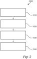
- controller 120 may be configured to perform, in accordance with some embodiments, will be described.
- the controller 120 may be configured to receive, at step 1010, an input signal representative of a desired luminous flux.
- the controller 120 may be configured to, at step 1020, select at least one LED filament 110 to which to provide power supply. Depending on the desired luminous flux, one or more of the LED filaments 110 may be selected.
- the controller 120 may further select, at step 1030, a power level of the at least one selected LED filament.
- the selected power level of a first selected LED filament (such as the first LED filament 110a) may differ from the selected power level of a second selected LED filament (such as the second LED filament 110b).
- the selected power levels of two or more selected LED filaments may also be (at least substantially) equal.
- controller 120 may be configured to, at step 1040, provide power supply to the at least one selected LED filament in accordance with the selected power levels.
- the combined luminous flux of the LED filament arrangement 105 (comprising the LED filaments 110a-c, which may individually be illuminated or turned off) may then correspond to the desired luminous flux.
- FIG. 3 shows a LED filament system 300, illustrated during dimming of the LED filament arrangement 305.
- the LED filament system 300 may be equivalent to the LED filament system 100.
- the controller 320 provides power supply to the LED filaments in the second mode, in which at least one LED filament is in an off-state.
- the controller 320 provides power supply to the first LED filament 310a, such that the first LED filament 310a is illuminated, thereby providing a luminous flux.
- the controller 320 does not provide power supply to the second LED filament 3 10b and the third LED filament 310c.
- the second LED filament 310b and the third LED filament 310c are thus not illuminated, and do not provide any luminous flux.
- the luminous flux of the LED filament arrangement 305 is thus provided by the first LED filament 310a.
- the luminous flux of the LED filament arrangement 305 may thus be in a range defined by the minimum and maximum flux of the first LED filament 310a.
- the controller may for example provide power supply to only one LED filament 310a if the input signal received by the controller corresponds to a desired luminous flux below a first limit.
- the LED filament arrangement 305 may have the appearance of one single LED filament.
- FIG 4 shows a LED filament system 400, in which all LED filaments 410a-c are illuminated and provided with a power above a first power level.
- the LED filament system 400 may be equivalent to the LED filament system 100 described with reference to Figures 1 and/or the LED filament system 300 described with reference to Figure 3 .
- the controller 420 provides power supply to the LED filaments 410a-c in the first mode, in which all the LED filaments 410a-c are provided with a power above a first power level. As the controller 420 provides power supply to all the LED filaments 410a-c, they are all illuminated, thereby each contributing to the luminous flux.
- the luminous flux of the LED filament arrangement 405 comprises luminous flux provided by all the LED filaments 410a-c.
- the luminous flux of the LED filament arrangement 405 may thus be in a range defined by the minimum flux of the three LED filaments 410a-c combined, and the maximum flux of the three LED filaments 410a-c combined.
- the controller may for example provide power supply to all the LED filaments 410a-c if the input signal received by the controller corresponds to a desired luminous flux above a second limit.
- LED filaments 410a-c are provided with a power above a first power level, they all emit light above a first light intensity level.
- the emitted light may, when seen at a certain distance, appear to originate from a continuous cylindrical surface.
- the light and illumination may be uniformly distributed around the LED filament arrangement 405.
- Figure 5 shows a graph of the relationship 530 between different input values (on the horizontal axis) and the corresponding luminous flux levels (on the vertical axis) of the LED filaments, in accordance with some embodiments.
- the relationship 530 describes the configuration of a controller of a LED filament system, such as any of the controllers 120-420 described above with reference to the preceding figures.
- the controller receives an input value In1, In2 corresponding to a desired luminous flux level L d1 , L d2 and provides powering to one or more LED filaments of the LED filament system, such that the LED filament arrangement provides the desired luminous flux.
- the controller For low input values (such as the first input In1), i.e. inputs corresponding to desired luminous flux below a maximum flux level L max of a first LED filament (such as the first desired luminous flux L d1 ), the controller is configured to provide powering to a first LED filament only.
- the first LED filament is thus illuminated and provides a first luminous flux 532.
- the powering level of the first LED filament is adapted such that the luminous flux 532 of the first LED filament reaches the desired luminous flux L d1 .
- the controller provides power to the first LED filament to provide maximum luminous flux 532.
- the controller further provides power to a second LED filament, such that it provides a second luminous flux 533.
- the power supplied to the second LED filament is adapted by the controller such that the total luminous flux 531 (formed by the addition or superposition of the first luminous flux 532 and the second luminous flux 533) reaches the desired luminous flux L d2 .
- the controller may provide power to a third LED filament, providing a third luminous flux 534, while maintaining the first luminous flux 532 and the second luminous flux 533 at the maximum flux level L max .
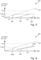
- Figure 6 shows a graph of the relationship 630 between different input values (on the horizontal axis) and the corresponding luminous flux levels (on the vertical axis) of the LED filaments, in accordance with some embodiments.
- a first LED filament is powered by the controller to provide luminous flux levels 632a up until a maximum flux level L max of a LED filament.
- the controller is configured to provide power supply to the first LED filament and a second LED filament at equal levels.
- the first LED filament provides a first luminous flux 632b equal to a second luminous flux 633 provided by the second LED filament.
- the power supply level of the first LED filament and the second LED filament is selected such that the combined luminous flux 631 reaches the desired luminous flux L d3 .
- Figure 7 shows a graph of the relationship 730 between different input values (on the horizontal axis) and the corresponding luminous flux levels (on the vertical axis) of the LED filaments, in accordance with some embodiments.
- luminous flux levels up until the maximum flux level L max are provided by a first LED filament (first luminous flux 732a).
- the controller is configured to provide power supply to a second LED filament.
- the controller decreases the power supply to the first LED filament such that the first luminous flux 732b decreases as the input increases.
- powering to the second LED filament is adapted such that the second luminous flux 733a increases at a higher rate than the decrease of the first luminous flux 732b.
- the first LED filament and the second LED filament provide luminous flux at the same level.
- the controller is configured to provide the first LED filament and the second LED filament with equal power supply.
- the first LED filament provides the first luminous flux 732c at the same level as the second luminous flux 733b provided by the second LED filament.
- the lighting device 850 comprises a LED filament system 800 comprising a plurality of LED filaments 810 and a controller 820.
- the LED filament system 800 may be equivalent to any of the LED filament systems 100-400, described above with reference to Figures 1-4 , except that it comprises four LED filaments 810, thereby forming a quadruple helix.
- the controller 820 may be configured to perform any of the methods described with reference to figures 2 , 5 , 6 or 7 .
- the lighting device further comprises an at least partially light-transmissive envelope 851, which envelops the LED filaments 810 of the LED filament system 800. Further, the lighting device comprises a base 852, on which the envelope 851 is mounted. The controller 820 is arranged at the base of the lighting device, and inside the envelope 851. However, in other embodiments, the controller 820 may be arranged within the base 852.
Landscapes
- Engineering & Computer Science (AREA)
- Physics & Mathematics (AREA)
- Microelectronics & Electronic Packaging (AREA)
- Optics & Photonics (AREA)
- General Engineering & Computer Science (AREA)
- Non-Portable Lighting Devices Or Systems Thereof (AREA)
Claims (10)
- Leuchtdioden-Filamentsystem, LED-Filamentsystem, (100), umfassend:eine LED-Filamentanordnung (105), umfassend eine Vielzahl von LED-Filamenten (110a-c), die eine Breite (W) aufweisen, wobeidie Vielzahl von LED-Filamenten um eine gemeinsame Mittelachse (A) herum derart gewickelt ist, dass jedes der LED-Filamente eine Spiralform aufweist,benachbarte LED-Filamente unterscheiden sich durch einen Translationsabstand (t) entlang der gemeinsamen Mittelachse (A), wobei dieser Translationsabstand (t) in einem Bereich von 1 bis 5 Mal der Breite (W) eines der LED-Filamente liegt, undeine Steuerung (120), die konfiguriert ist, um die Leistungsversorgung der LED-Filamente derart zu steuern, dass mindestens eines der Vielzahl von LED-Filamenten individuell steuerbar ist, wobeiwobei die Steuerung konfiguriert ist, um die Leistungsversorgung der LED-Filamente in einem ersten Modus, in dem alle LED-Filamente in einem Ein-Zustand sind, und die Steuerung eine Leistungsversorgung über einem ersten Leistungspegel an die LED-Filamente bereitstellt, und in einem zweiten Modus, in dem mindestens eines der LED-Filamente in einem Aus-Zustand ist, zu steuern, undwobei, für einen gegebenen Translationsabstand (t), die LED-Filamentanordnung eine Lichtverteilung bereitstellt, die in dem ersten Modus einer gleichmäßigen Licht emittierenden Oberfläche und in dem zweiten Modus mindestens einer Licht emittierenden Spirale entspricht,dadurch gekennzeichnet, dass die Steuerung konfiguriert ist zum: Empfangen (1010) eines Eingangssignals, das einen gewünschten Lichtstrom darstellt;Auswählen (1020), basierend auf dem gewünschten Lichtstrom, von mindestens einem LED-Filament, um diesem eine Leistungsversorgung bereitzustellen;Auswählen (1030) einer Leistungspegels des mindestens einen ausgewählten LED-Filaments, um den gewünschten Lichtstrom bereitzustellen; undVersorgen (1040), gemäß dem ausgewählten Leistungspegel, des mindestens einen ausgewählten LED-Filaments mit Leistung undwobei, falls der gewünschte Lichtstrom (LD) unter einem ersten Grenzwert (Lmax) liegt, die Steuerung konfiguriert ist, um nur ein LED-Filament (310c) mit Leistung zu versorgen, und falls der gewünschte Lichtstrom über einem zweiten Grenzwert liegt, die Steuerung konfiguriert ist, um alle LED-Filamente (410a, 410b, 410c) der LED-Filamentanordnung (405) mit Leistung zu versorgen.
- LED-Filamentsystem nach einem der vorstehenden Ansprüche, wobei jedes der LED-Filamente in einer Spiralform angeordnet ist, die eine im Wesentlichen konstante Spiralsteigung (p) aufweist.
- LED-Filamentsystem nach Anspruch 2, wobei die Spiralsteigung (p) in einem Bereich vom 8 bis 20 Mal der Breite (W) eines der LED-Filamente liegt.
- LED-Filamentsystem nach einem der vorstehenden Ansprüche, wobei die Breite (W) in einem Bereich von 1 bis 4 mm liegt.
- LED-Filamentsystem nach einem der vorstehenden Ansprüche, wobei die Steuerung ferner konfiguriert ist, um, falls der gewünschte Lichtstrom über einem Schwellenwert liegt, der einem maximalen Strompegel eines ersten LED-Filaments entspricht:Versorgen des ersten LED-Filaments mit Leistung entsprechend dem maximalen Strompegel; undVersorgen eines zweiten LED-Filaments mit Leistung, um den gewünschten Lichtstrom zu erreichen.
- LED-Filamentsystem nach einem der vorstehenden Ansprüche, wobei die Steuerung ferner konfiguriert ist, um, falls der gewünschte Lichtstrom über einem Schwellenwert liegt, der einem maximalen Strompegel eines ersten LED-Filaments entspricht:
Versorgen des ersten LED-Filaments und mindestens eines zweiten LED-Filaments mit Leistung in gleichem Maße. - LED-Filamentsystem nach einem der vorstehenden Ansprüche, wobei die Steuerung ferner konfiguriert ist zum:falls der gewünschte Lichtstrom über einem ersten Schwellenwert, der einem maximalen Strompegel eines ersten LED-Filaments entspricht, und unter einem zweiten Schwellenwert liegt, Bereitstellen von Leistung an das erste LED-Filament auf einem ersten Pegel, der niedriger als der maximale Strompegel ist, und Bereitstellen von Leistung an ein zweites LED-Filament auf einem Pegel, der niedriger als der erste Pegel ist; undfalls der gewünschte Lichtstrom über dem zweiten Schwellenwert liegt, Bereitstellen von Leistung an das erste LED-Filament und ein zweites LED-Filament in gleichem Maße.
- LED-Filamentsystem nach einem der vorstehenden Ansprüche, wobei jedes der LED-Filamente in einer Spiralform angeordnet ist, die einen im Wesentlichen konstanten Radius (r) aufweist.
- LED-Filamentsystem nach einem der vorstehenden Ansprüche, wobei die LED-Filamentanordnung 2 bis 8 LED-Filamente umfasst.
- Beleuchtungsvorrichtung (850), umfassend:ein LED-Filamentsystem (800) nach einem der vorstehenden Ansprüche;eine mindestens teilweise lichtdurchlässige Hülle (851), die das mindestens eine LED-Filament der LED-Filamentanordnung umhüllt; undeine Basis (852), auf der die Hülle montiert ist, wobei die Basis angepasst ist, um mit einem Leuchtensockel verbunden zu werden.
Applications Claiming Priority (2)
| Application Number | Priority Date | Filing Date | Title |
|---|---|---|---|
| EP20160319 | 2020-03-02 | ||
| PCT/EP2021/054325 WO2021175637A1 (en) | 2020-03-02 | 2021-02-22 | Dimmable helix led filament arrangement and lamp |
Publications (2)
| Publication Number | Publication Date |
|---|---|
| EP4115708A1 EP4115708A1 (de) | 2023-01-11 |
| EP4115708B1 true EP4115708B1 (de) | 2024-07-17 |
Family
ID=69743085
Family Applications (1)
| Application Number | Title | Priority Date | Filing Date |
|---|---|---|---|
| EP21706581.2A Active EP4115708B1 (de) | 2020-03-02 | 2021-02-22 | Dimmbare spiral-led-filamentanordnung und lampe |
Country Status (4)
| Country | Link |
|---|---|
| US (1) | US11985738B2 (de) |
| EP (1) | EP4115708B1 (de) |
| CN (1) | CN115245051A (de) |
| WO (1) | WO2021175637A1 (de) |
Families Citing this family (4)
| Publication number | Priority date | Publication date | Assignee | Title |
|---|---|---|---|---|
| USD1064330S1 (en) * | 2021-08-02 | 2025-02-25 | Jiaxing Super Lighting Electric Appliance Co., Ltd | Light bulb |
| CA227209S (en) * | 2021-10-21 | 2024-01-31 | Jiaxing Super Lighting Electric Appliance Co Ltd | Light bulb |
| US20250189087A1 (en) * | 2022-02-24 | 2025-06-12 | Signify Holding B.V. | Led filament |
| WO2026052584A1 (en) * | 2024-09-09 | 2026-03-12 | Signify Holding B.V. | A led filament comprising a led filament assembly of a plurality of intertwined sub-led filaments |
Family Cites Families (15)
| Publication number | Priority date | Publication date | Assignee | Title |
|---|---|---|---|---|
| US10655792B2 (en) * | 2014-09-28 | 2020-05-19 | Zhejiang Super Lighting Electric Appliance Co., Ltd. | LED bulb lamp |
| ITTO20110132A1 (it) * | 2011-02-16 | 2012-08-17 | Cyberdyne Di Greggio Dario | Dimmer per lampadina a led e lampadina a led associata. |
| US8847513B2 (en) * | 2011-03-08 | 2014-09-30 | Cree, Inc. | Method and apparatus for controlling light output color and/or brightness |
| US10845008B2 (en) * | 2014-09-28 | 2020-11-24 | Zhejiang Super Lighting Electric Appliance Co., Ltd. | LED filament and LED light bulb |
| HK1207250A2 (en) * | 2014-10-15 | 2016-01-22 | 新照明设计有限公司 | Substrate for led package, a tridimensional led package having the substrate, a light bulb having the tridimensional led package and methods for producing the same |
| RU2704605C2 (ru) * | 2015-02-03 | 2019-10-30 | Филипс Лайтинг Холдинг Б.В. | Блок нити накала для модернизированной светодиодной трубки |
| US10415763B2 (en) | 2016-02-04 | 2019-09-17 | Osram Opto Semiconductors Gmbh | LED-filament and illuminant with LED-filament |
| US20180094777A1 (en) * | 2016-10-04 | 2018-04-05 | Burton VARGAS-CHAMBERS | Flexible led filament |
| CN108050399A (zh) | 2017-12-06 | 2018-05-18 | 广明源光科技股份有限公司 | 一种灯丝灯结构 |
| WO2019197394A1 (en) | 2018-04-11 | 2019-10-17 | Signify Holding B.V. | Led filament lamp of candle light appearance |
| CN110081323B (zh) * | 2018-05-23 | 2021-08-31 | 浙江山蒲照明电器有限公司 | Led灯丝及led球泡灯 |
| US10473273B1 (en) * | 2018-06-15 | 2019-11-12 | Ledvance Llc | Lamp with inductive connection to light engine |
| CN209229385U (zh) * | 2018-12-29 | 2019-08-09 | 漳州立达信光电子科技有限公司 | Led灯丝及灯泡 |
| CN209672092U (zh) | 2019-03-14 | 2019-11-22 | 漳州立达信光电子科技有限公司 | 一种led灯具 |
| CN209782275U (zh) * | 2019-04-18 | 2019-12-13 | 漳州立达信光电子科技有限公司 | 一种柔性灯丝灯具 |
-
2021
- 2021-02-22 EP EP21706581.2A patent/EP4115708B1/de active Active
- 2021-02-22 WO PCT/EP2021/054325 patent/WO2021175637A1/en not_active Ceased
- 2021-02-22 US US17/908,491 patent/US11985738B2/en active Active
- 2021-02-22 CN CN202180018425.3A patent/CN115245051A/zh active Pending
Also Published As
| Publication number | Publication date |
|---|---|
| EP4115708A1 (de) | 2023-01-11 |
| WO2021175637A1 (en) | 2021-09-10 |
| US20230091712A1 (en) | 2023-03-23 |
| CN115245051A (zh) | 2022-10-25 |
| US11985738B2 (en) | 2024-05-14 |
Similar Documents
| Publication | Publication Date | Title |
|---|---|---|
| EP4115708B1 (de) | Dimmbare spiral-led-filamentanordnung und lampe | |
| CN114144614B (zh) | 具有平滑过渡的颜色可控led灯丝 | |
| EP3987218B1 (de) | Farbtemperatursteuerbare beleuchtungsvorrichtung mit unterschiedlichen led-filamenten | |
| EP4004434B1 (de) | Farbsteuerbares led-filament und lampe mit solch einem filament | |
| CN113330245B (zh) | Led灯丝装置 | |
| EP4004432B1 (de) | Led-filament-anordnung | |
| US12188622B2 (en) | Lighting device | |
| EP4464128B1 (de) | Led-filament zur beleuchtung und desinfektion | |
| EP4144185B1 (de) | Abstimmbare lichtemittierende vorrichtung | |
| EP4666002A1 (de) | Led-filamentanordnung | |
| WO2025157711A1 (en) | A led filament arrangement | |
| EP4136938A1 (de) | Farbtemperatursteuerbare led-glühlampe mit verbesserter lichtqualität |
Legal Events
| Date | Code | Title | Description |
|---|---|---|---|
| STAA | Information on the status of an ep patent application or granted ep patent |
Free format text: STATUS: UNKNOWN |
|
| STAA | Information on the status of an ep patent application or granted ep patent |
Free format text: STATUS: THE INTERNATIONAL PUBLICATION HAS BEEN MADE |
|
| PUAI | Public reference made under article 153(3) epc to a published international application that has entered the european phase |
Free format text: ORIGINAL CODE: 0009012 |
|
| STAA | Information on the status of an ep patent application or granted ep patent |
Free format text: STATUS: REQUEST FOR EXAMINATION WAS MADE |
|
| 17P | Request for examination filed |
Effective date: 20221004 |
|
| AK | Designated contracting states |
Kind code of ref document: A1 Designated state(s): AL AT BE BG CH CY CZ DE DK EE ES FI FR GB GR HR HU IE IS IT LI LT LU LV MC MK MT NL NO PL PT RO RS SE SI SK SM TR |
|
| DAV | Request for validation of the european patent (deleted) | ||
| DAX | Request for extension of the european patent (deleted) | ||
| REG | Reference to a national code |
Ref country code: DE Ref legal event code: R079 Free format text: PREVIOUS MAIN CLASS: H05B0045100000 Ipc: F21K0009232000 Ref document number: 602021015800 Country of ref document: DE |
|
| GRAP | Despatch of communication of intention to grant a patent |
Free format text: ORIGINAL CODE: EPIDOSNIGR1 |
|
| STAA | Information on the status of an ep patent application or granted ep patent |
Free format text: STATUS: GRANT OF PATENT IS INTENDED |
|
| RIC1 | Information provided on ipc code assigned before grant |
Ipc: H05B 45/10 20200101ALI20240129BHEP Ipc: F21Y 115/10 20160101ALI20240129BHEP Ipc: F21K 9/232 20160101AFI20240129BHEP |
|
| INTG | Intention to grant announced |
Effective date: 20240212 |
|
| GRAS | Grant fee paid |
Free format text: ORIGINAL CODE: EPIDOSNIGR3 |
|
| GRAA | (expected) grant |
Free format text: ORIGINAL CODE: 0009210 |
|
| STAA | Information on the status of an ep patent application or granted ep patent |
Free format text: STATUS: THE PATENT HAS BEEN GRANTED |
|
| AK | Designated contracting states |
Kind code of ref document: B1 Designated state(s): AL AT BE BG CH CY CZ DE DK EE ES FI FR GB GR HR HU IE IS IT LI LT LU LV MC MK MT NL NO PL PT RO RS SE SI SK SM TR |
|
| P01 | Opt-out of the competence of the unified patent court (upc) registered |
Free format text: CASE NUMBER: APP_33895/2024 Effective date: 20240606 |
|
| REG | Reference to a national code |
Ref country code: CH Ref legal event code: EP |
|
| REG | Reference to a national code |
Ref country code: DE Ref legal event code: R096 Ref document number: 602021015800 Country of ref document: DE |
|
| REG | Reference to a national code |
Ref country code: IE Ref legal event code: FG4D |
|
| REG | Reference to a national code |
Ref country code: LT Ref legal event code: MG9D |
|
| REG | Reference to a national code |
Ref country code: NL Ref legal event code: MP Effective date: 20240717 |
|
| PG25 | Lapsed in a contracting state [announced via postgrant information from national office to epo] |
Ref country code: PT Free format text: LAPSE BECAUSE OF FAILURE TO SUBMIT A TRANSLATION OF THE DESCRIPTION OR TO PAY THE FEE WITHIN THE PRESCRIBED TIME-LIMIT Effective date: 20241118 |
|
| REG | Reference to a national code |
Ref country code: AT Ref legal event code: MK05 Ref document number: 1704452 Country of ref document: AT Kind code of ref document: T Effective date: 20240717 |
|
| PG25 | Lapsed in a contracting state [announced via postgrant information from national office to epo] |
Ref country code: NL Free format text: LAPSE BECAUSE OF FAILURE TO SUBMIT A TRANSLATION OF THE DESCRIPTION OR TO PAY THE FEE WITHIN THE PRESCRIBED TIME-LIMIT Effective date: 20240717 |
|
| PG25 | Lapsed in a contracting state [announced via postgrant information from national office to epo] |
Ref country code: PT Free format text: LAPSE BECAUSE OF FAILURE TO SUBMIT A TRANSLATION OF THE DESCRIPTION OR TO PAY THE FEE WITHIN THE PRESCRIBED TIME-LIMIT Effective date: 20241118 Ref country code: NL Free format text: LAPSE BECAUSE OF FAILURE TO SUBMIT A TRANSLATION OF THE DESCRIPTION OR TO PAY THE FEE WITHIN THE PRESCRIBED TIME-LIMIT Effective date: 20240717 |
|
| PG25 | Lapsed in a contracting state [announced via postgrant information from national office to epo] |
Ref country code: NO Free format text: LAPSE BECAUSE OF FAILURE TO SUBMIT A TRANSLATION OF THE DESCRIPTION OR TO PAY THE FEE WITHIN THE PRESCRIBED TIME-LIMIT Effective date: 20241017 |
|
| PG25 | Lapsed in a contracting state [announced via postgrant information from national office to epo] |
Ref country code: GR Free format text: LAPSE BECAUSE OF FAILURE TO SUBMIT A TRANSLATION OF THE DESCRIPTION OR TO PAY THE FEE WITHIN THE PRESCRIBED TIME-LIMIT Effective date: 20241018 Ref country code: PL Free format text: LAPSE BECAUSE OF FAILURE TO SUBMIT A TRANSLATION OF THE DESCRIPTION OR TO PAY THE FEE WITHIN THE PRESCRIBED TIME-LIMIT Effective date: 20240717 Ref country code: FI Free format text: LAPSE BECAUSE OF FAILURE TO SUBMIT A TRANSLATION OF THE DESCRIPTION OR TO PAY THE FEE WITHIN THE PRESCRIBED TIME-LIMIT Effective date: 20240717 |
|
| PG25 | Lapsed in a contracting state [announced via postgrant information from national office to epo] |
Ref country code: BG Free format text: LAPSE BECAUSE OF FAILURE TO SUBMIT A TRANSLATION OF THE DESCRIPTION OR TO PAY THE FEE WITHIN THE PRESCRIBED TIME-LIMIT Effective date: 20240717 |
|
| PG25 | Lapsed in a contracting state [announced via postgrant information from national office to epo] |
Ref country code: LV Free format text: LAPSE BECAUSE OF FAILURE TO SUBMIT A TRANSLATION OF THE DESCRIPTION OR TO PAY THE FEE WITHIN THE PRESCRIBED TIME-LIMIT Effective date: 20240717 |
|
| PG25 | Lapsed in a contracting state [announced via postgrant information from national office to epo] |
Ref country code: IS Free format text: LAPSE BECAUSE OF FAILURE TO SUBMIT A TRANSLATION OF THE DESCRIPTION OR TO PAY THE FEE WITHIN THE PRESCRIBED TIME-LIMIT Effective date: 20241117 Ref country code: AT Free format text: LAPSE BECAUSE OF FAILURE TO SUBMIT A TRANSLATION OF THE DESCRIPTION OR TO PAY THE FEE WITHIN THE PRESCRIBED TIME-LIMIT Effective date: 20240717 |
|
| PG25 | Lapsed in a contracting state [announced via postgrant information from national office to epo] |
Ref country code: HR Free format text: LAPSE BECAUSE OF FAILURE TO SUBMIT A TRANSLATION OF THE DESCRIPTION OR TO PAY THE FEE WITHIN THE PRESCRIBED TIME-LIMIT Effective date: 20240717 |
|
| PG25 | Lapsed in a contracting state [announced via postgrant information from national office to epo] |
Ref country code: RS Free format text: LAPSE BECAUSE OF FAILURE TO SUBMIT A TRANSLATION OF THE DESCRIPTION OR TO PAY THE FEE WITHIN THE PRESCRIBED TIME-LIMIT Effective date: 20241017 Ref country code: ES Free format text: LAPSE BECAUSE OF FAILURE TO SUBMIT A TRANSLATION OF THE DESCRIPTION OR TO PAY THE FEE WITHIN THE PRESCRIBED TIME-LIMIT Effective date: 20240717 |
|
| PG25 | Lapsed in a contracting state [announced via postgrant information from national office to epo] |
Ref country code: RS Free format text: LAPSE BECAUSE OF FAILURE TO SUBMIT A TRANSLATION OF THE DESCRIPTION OR TO PAY THE FEE WITHIN THE PRESCRIBED TIME-LIMIT Effective date: 20241017 Ref country code: PL Free format text: LAPSE BECAUSE OF FAILURE TO SUBMIT A TRANSLATION OF THE DESCRIPTION OR TO PAY THE FEE WITHIN THE PRESCRIBED TIME-LIMIT Effective date: 20240717 Ref country code: NO Free format text: LAPSE BECAUSE OF FAILURE TO SUBMIT A TRANSLATION OF THE DESCRIPTION OR TO PAY THE FEE WITHIN THE PRESCRIBED TIME-LIMIT Effective date: 20241017 Ref country code: LV Free format text: LAPSE BECAUSE OF FAILURE TO SUBMIT A TRANSLATION OF THE DESCRIPTION OR TO PAY THE FEE WITHIN THE PRESCRIBED TIME-LIMIT Effective date: 20240717 Ref country code: IS Free format text: LAPSE BECAUSE OF FAILURE TO SUBMIT A TRANSLATION OF THE DESCRIPTION OR TO PAY THE FEE WITHIN THE PRESCRIBED TIME-LIMIT Effective date: 20241117 Ref country code: HR Free format text: LAPSE BECAUSE OF FAILURE TO SUBMIT A TRANSLATION OF THE DESCRIPTION OR TO PAY THE FEE WITHIN THE PRESCRIBED TIME-LIMIT Effective date: 20240717 Ref country code: GR Free format text: LAPSE BECAUSE OF FAILURE TO SUBMIT A TRANSLATION OF THE DESCRIPTION OR TO PAY THE FEE WITHIN THE PRESCRIBED TIME-LIMIT Effective date: 20241018 Ref country code: FI Free format text: LAPSE BECAUSE OF FAILURE TO SUBMIT A TRANSLATION OF THE DESCRIPTION OR TO PAY THE FEE WITHIN THE PRESCRIBED TIME-LIMIT Effective date: 20240717 Ref country code: ES Free format text: LAPSE BECAUSE OF FAILURE TO SUBMIT A TRANSLATION OF THE DESCRIPTION OR TO PAY THE FEE WITHIN THE PRESCRIBED TIME-LIMIT Effective date: 20240717 Ref country code: BG Free format text: LAPSE BECAUSE OF FAILURE TO SUBMIT A TRANSLATION OF THE DESCRIPTION OR TO PAY THE FEE WITHIN THE PRESCRIBED TIME-LIMIT Effective date: 20240717 Ref country code: AT Free format text: LAPSE BECAUSE OF FAILURE TO SUBMIT A TRANSLATION OF THE DESCRIPTION OR TO PAY THE FEE WITHIN THE PRESCRIBED TIME-LIMIT Effective date: 20240717 |
|
| PG25 | Lapsed in a contracting state [announced via postgrant information from national office to epo] |
Ref country code: SM Free format text: LAPSE BECAUSE OF FAILURE TO SUBMIT A TRANSLATION OF THE DESCRIPTION OR TO PAY THE FEE WITHIN THE PRESCRIBED TIME-LIMIT Effective date: 20240717 Ref country code: RO Free format text: LAPSE BECAUSE OF FAILURE TO SUBMIT A TRANSLATION OF THE DESCRIPTION OR TO PAY THE FEE WITHIN THE PRESCRIBED TIME-LIMIT Effective date: 20240717 Ref country code: DK Free format text: LAPSE BECAUSE OF FAILURE TO SUBMIT A TRANSLATION OF THE DESCRIPTION OR TO PAY THE FEE WITHIN THE PRESCRIBED TIME-LIMIT Effective date: 20240717 |
|
| REG | Reference to a national code |
Ref country code: DE Ref legal event code: R097 Ref document number: 602021015800 Country of ref document: DE |
|
| PG25 | Lapsed in a contracting state [announced via postgrant information from national office to epo] |
Ref country code: EE Free format text: LAPSE BECAUSE OF FAILURE TO SUBMIT A TRANSLATION OF THE DESCRIPTION OR TO PAY THE FEE WITHIN THE PRESCRIBED TIME-LIMIT Effective date: 20240717 |
|
| PG25 | Lapsed in a contracting state [announced via postgrant information from national office to epo] |
Ref country code: CZ Free format text: LAPSE BECAUSE OF FAILURE TO SUBMIT A TRANSLATION OF THE DESCRIPTION OR TO PAY THE FEE WITHIN THE PRESCRIBED TIME-LIMIT Effective date: 20240717 |
|
| PGFP | Annual fee paid to national office [announced via postgrant information from national office to epo] |
Ref country code: FR Payment date: 20250224 Year of fee payment: 5 |
|
| PG25 | Lapsed in a contracting state [announced via postgrant information from national office to epo] |
Ref country code: SK Free format text: LAPSE BECAUSE OF FAILURE TO SUBMIT A TRANSLATION OF THE DESCRIPTION OR TO PAY THE FEE WITHIN THE PRESCRIBED TIME-LIMIT Effective date: 20240717 |
|
| PGFP | Annual fee paid to national office [announced via postgrant information from national office to epo] |
Ref country code: GB Payment date: 20250218 Year of fee payment: 5 |
|
| PLBE | No opposition filed within time limit |
Free format text: ORIGINAL CODE: 0009261 |
|
| STAA | Information on the status of an ep patent application or granted ep patent |
Free format text: STATUS: NO OPPOSITION FILED WITHIN TIME LIMIT |
|
| 26N | No opposition filed |
Effective date: 20250422 |
|
| PGFP | Annual fee paid to national office [announced via postgrant information from national office to epo] |
Ref country code: DE Payment date: 20250428 Year of fee payment: 5 |
|
| PG25 | Lapsed in a contracting state [announced via postgrant information from national office to epo] |
Ref country code: SE Free format text: LAPSE BECAUSE OF FAILURE TO SUBMIT A TRANSLATION OF THE DESCRIPTION OR TO PAY THE FEE WITHIN THE PRESCRIBED TIME-LIMIT Effective date: 20240717 |
|
| PG25 | Lapsed in a contracting state [announced via postgrant information from national office to epo] |
Ref country code: MC Free format text: LAPSE BECAUSE OF FAILURE TO SUBMIT A TRANSLATION OF THE DESCRIPTION OR TO PAY THE FEE WITHIN THE PRESCRIBED TIME-LIMIT Effective date: 20240717 |
|
| REG | Reference to a national code |
Ref country code: CH Ref legal event code: PL |
|
| PG25 | Lapsed in a contracting state [announced via postgrant information from national office to epo] |
Ref country code: LU Free format text: LAPSE BECAUSE OF NON-PAYMENT OF DUE FEES Effective date: 20250222 |
|
| PG25 | Lapsed in a contracting state [announced via postgrant information from national office to epo] |
Ref country code: CH Free format text: LAPSE BECAUSE OF NON-PAYMENT OF DUE FEES Effective date: 20250228 |
|
| REG | Reference to a national code |
Ref country code: BE Ref legal event code: MM Effective date: 20250228 |
|
| PG25 | Lapsed in a contracting state [announced via postgrant information from national office to epo] |
Ref country code: BE Free format text: LAPSE BECAUSE OF NON-PAYMENT OF DUE FEES Effective date: 20250228 |
|
| PG25 | Lapsed in a contracting state [announced via postgrant information from national office to epo] |
Ref country code: IE Free format text: LAPSE BECAUSE OF NON-PAYMENT OF DUE FEES Effective date: 20250222 |
|
| PG25 | Lapsed in a contracting state [announced via postgrant information from national office to epo] |
Ref country code: IT Free format text: LAPSE BECAUSE OF FAILURE TO SUBMIT A TRANSLATION OF THE DESCRIPTION OR TO PAY THE FEE WITHIN THE PRESCRIBED TIME-LIMIT Effective date: 20240717 |