EP4116122B1 - Transmission électrique pour un véhicule - Google Patents
Transmission électrique pour un véhicule Download PDFInfo
- Publication number
- EP4116122B1 EP4116122B1 EP21184361.0A EP21184361A EP4116122B1 EP 4116122 B1 EP4116122 B1 EP 4116122B1 EP 21184361 A EP21184361 A EP 21184361A EP 4116122 B1 EP4116122 B1 EP 4116122B1
- Authority
- EP
- European Patent Office
- Prior art keywords
- gear
- shaft
- electric
- vehicle
- extremity
- Prior art date
- Legal status (The legal status is an assumption and is not a legal conclusion. Google has not performed a legal analysis and makes no representation as to the accuracy of the status listed.)
- Active
Links
Images


Classifications
-
- B—PERFORMING OPERATIONS; TRANSPORTING
- B60—VEHICLES IN GENERAL
- B60K—ARRANGEMENT OR MOUNTING OF PROPULSION UNITS OR OF TRANSMISSIONS IN VEHICLES; ARRANGEMENT OR MOUNTING OF PLURAL DIVERSE PRIME-MOVERS IN VEHICLES; AUXILIARY DRIVES FOR VEHICLES; INSTRUMENTATION OR DASHBOARDS FOR VEHICLES; ARRANGEMENTS IN CONNECTION WITH COOLING, AIR INTAKE, GAS EXHAUST OR FUEL SUPPLY OF PROPULSION UNITS IN VEHICLES
- B60K17/00—Arrangement or mounting of transmissions in vehicles
- B60K17/04—Arrangement or mounting of transmissions in vehicles characterised by arrangement, location or kind of gearing
- B60K17/16—Arrangement or mounting of transmissions in vehicles characterised by arrangement, location or kind of gearing of differential gearing
-
- B—PERFORMING OPERATIONS; TRANSPORTING
- B60—VEHICLES IN GENERAL
- B60K—ARRANGEMENT OR MOUNTING OF PROPULSION UNITS OR OF TRANSMISSIONS IN VEHICLES; ARRANGEMENT OR MOUNTING OF PLURAL DIVERSE PRIME-MOVERS IN VEHICLES; AUXILIARY DRIVES FOR VEHICLES; INSTRUMENTATION OR DASHBOARDS FOR VEHICLES; ARRANGEMENTS IN CONNECTION WITH COOLING, AIR INTAKE, GAS EXHAUST OR FUEL SUPPLY OF PROPULSION UNITS IN VEHICLES
- B60K7/00—Disposition of motor in, or adjacent to, traction wheel
- B60K7/0007—Disposition of motor in, or adjacent to, traction wheel the motor being electric
-
- B—PERFORMING OPERATIONS; TRANSPORTING
- B60—VEHICLES IN GENERAL
- B60K—ARRANGEMENT OR MOUNTING OF PROPULSION UNITS OR OF TRANSMISSIONS IN VEHICLES; ARRANGEMENT OR MOUNTING OF PLURAL DIVERSE PRIME-MOVERS IN VEHICLES; AUXILIARY DRIVES FOR VEHICLES; INSTRUMENTATION OR DASHBOARDS FOR VEHICLES; ARRANGEMENTS IN CONNECTION WITH COOLING, AIR INTAKE, GAS EXHAUST OR FUEL SUPPLY OF PROPULSION UNITS IN VEHICLES
- B60K1/00—Arrangement or mounting of electrical propulsion units
- B60K1/02—Arrangement or mounting of electrical propulsion units comprising more than one electric motor
-
- B—PERFORMING OPERATIONS; TRANSPORTING
- B60—VEHICLES IN GENERAL
- B60K—ARRANGEMENT OR MOUNTING OF PROPULSION UNITS OR OF TRANSMISSIONS IN VEHICLES; ARRANGEMENT OR MOUNTING OF PLURAL DIVERSE PRIME-MOVERS IN VEHICLES; AUXILIARY DRIVES FOR VEHICLES; INSTRUMENTATION OR DASHBOARDS FOR VEHICLES; ARRANGEMENTS IN CONNECTION WITH COOLING, AIR INTAKE, GAS EXHAUST OR FUEL SUPPLY OF PROPULSION UNITS IN VEHICLES
- B60K17/00—Arrangement or mounting of transmissions in vehicles
- B60K17/04—Arrangement or mounting of transmissions in vehicles characterised by arrangement, location or kind of gearing
- B60K17/06—Arrangement or mounting of transmissions in vehicles characterised by arrangement, location or kind of gearing of change-speed gearing
-
- B—PERFORMING OPERATIONS; TRANSPORTING
- B60—VEHICLES IN GENERAL
- B60K—ARRANGEMENT OR MOUNTING OF PROPULSION UNITS OR OF TRANSMISSIONS IN VEHICLES; ARRANGEMENT OR MOUNTING OF PLURAL DIVERSE PRIME-MOVERS IN VEHICLES; AUXILIARY DRIVES FOR VEHICLES; INSTRUMENTATION OR DASHBOARDS FOR VEHICLES; ARRANGEMENTS IN CONNECTION WITH COOLING, AIR INTAKE, GAS EXHAUST OR FUEL SUPPLY OF PROPULSION UNITS IN VEHICLES
- B60K17/00—Arrangement or mounting of transmissions in vehicles
- B60K17/04—Arrangement or mounting of transmissions in vehicles characterised by arrangement, location or kind of gearing
- B60K17/16—Arrangement or mounting of transmissions in vehicles characterised by arrangement, location or kind of gearing of differential gearing
- B60K17/165—Arrangement or mounting of transmissions in vehicles characterised by arrangement, location or kind of gearing of differential gearing provided between independent half axles
-
- B—PERFORMING OPERATIONS; TRANSPORTING
- B60—VEHICLES IN GENERAL
- B60K—ARRANGEMENT OR MOUNTING OF PROPULSION UNITS OR OF TRANSMISSIONS IN VEHICLES; ARRANGEMENT OR MOUNTING OF PLURAL DIVERSE PRIME-MOVERS IN VEHICLES; AUXILIARY DRIVES FOR VEHICLES; INSTRUMENTATION OR DASHBOARDS FOR VEHICLES; ARRANGEMENTS IN CONNECTION WITH COOLING, AIR INTAKE, GAS EXHAUST OR FUEL SUPPLY OF PROPULSION UNITS IN VEHICLES
- B60K17/00—Arrangement or mounting of transmissions in vehicles
- B60K17/28—Arrangement or mounting of transmissions in vehicles characterised by arrangement, location, or type of power take-off
-
- F—MECHANICAL ENGINEERING; LIGHTING; HEATING; WEAPONS; BLASTING
- F16—ENGINEERING ELEMENTS AND UNITS; GENERAL MEASURES FOR PRODUCING AND MAINTAINING EFFECTIVE FUNCTIONING OF MACHINES OR INSTALLATIONS; THERMAL INSULATION IN GENERAL
- F16H—GEARING
- F16H37/00—Combinations of mechanical gearings, not provided for in groups F16H1/00 - F16H35/00
- F16H37/02—Combinations of mechanical gearings, not provided for in groups F16H1/00 - F16H35/00 comprising essentially only toothed or friction gearings
- F16H37/06—Combinations of mechanical gearings, not provided for in groups F16H1/00 - F16H35/00 comprising essentially only toothed or friction gearings with a plurality of driving or driven shafts; with arrangements for dividing torque between two or more intermediate shafts
- F16H37/08—Combinations of mechanical gearings, not provided for in groups F16H1/00 - F16H35/00 comprising essentially only toothed or friction gearings with a plurality of driving or driven shafts; with arrangements for dividing torque between two or more intermediate shafts with differential gearing
- F16H37/0806—Combinations of mechanical gearings, not provided for in groups F16H1/00 - F16H35/00 comprising essentially only toothed or friction gearings with a plurality of driving or driven shafts; with arrangements for dividing torque between two or more intermediate shafts with differential gearing with a plurality of driving or driven shafts
-
- B—PERFORMING OPERATIONS; TRANSPORTING
- B60—VEHICLES IN GENERAL
- B60K—ARRANGEMENT OR MOUNTING OF PROPULSION UNITS OR OF TRANSMISSIONS IN VEHICLES; ARRANGEMENT OR MOUNTING OF PLURAL DIVERSE PRIME-MOVERS IN VEHICLES; AUXILIARY DRIVES FOR VEHICLES; INSTRUMENTATION OR DASHBOARDS FOR VEHICLES; ARRANGEMENTS IN CONNECTION WITH COOLING, AIR INTAKE, GAS EXHAUST OR FUEL SUPPLY OF PROPULSION UNITS IN VEHICLES
- B60K1/00—Arrangement or mounting of electrical propulsion units
- B60K2001/001—Arrangement or mounting of electrical propulsion units one motor mounted on a propulsion axle for rotating right and left wheels of this axle
-
- B—PERFORMING OPERATIONS; TRANSPORTING
- B60—VEHICLES IN GENERAL
- B60K—ARRANGEMENT OR MOUNTING OF PROPULSION UNITS OR OF TRANSMISSIONS IN VEHICLES; ARRANGEMENT OR MOUNTING OF PLURAL DIVERSE PRIME-MOVERS IN VEHICLES; AUXILIARY DRIVES FOR VEHICLES; INSTRUMENTATION OR DASHBOARDS FOR VEHICLES; ARRANGEMENTS IN CONNECTION WITH COOLING, AIR INTAKE, GAS EXHAUST OR FUEL SUPPLY OF PROPULSION UNITS IN VEHICLES
- B60K25/00—Auxiliary drives
- B60K2025/005—Auxiliary drives driven by electric motors forming part of the propulsion unit
-
- B—PERFORMING OPERATIONS; TRANSPORTING
- B60—VEHICLES IN GENERAL
- B60Y—INDEXING SCHEME RELATING TO ASPECTS CROSS-CUTTING VEHICLE TECHNOLOGY
- B60Y2200/00—Type of vehicle
- B60Y2200/10—Road Vehicles
- B60Y2200/14—Trucks; Load vehicles, Busses
-
- B—PERFORMING OPERATIONS; TRANSPORTING
- B60—VEHICLES IN GENERAL
- B60Y—INDEXING SCHEME RELATING TO ASPECTS CROSS-CUTTING VEHICLE TECHNOLOGY
- B60Y2200/00—Type of vehicle
- B60Y2200/10—Road Vehicles
- B60Y2200/14—Trucks; Load vehicles, Busses
- B60Y2200/145—Haulage vehicles, trailing trucks
Definitions
- the invention applies to an electric powertrain integrated into a vehicle axle.
- Such electric axle (or “E-axle”) is a front or rear axle that includes an axle body (or “housing”) adapted to receive a powertrain, which is arranged to provide torque to the wheels of the axle.
- the "E-Axle” is a compact and economical electric drive solution for battery electric vehicles, fuel cells and hybrid applications. The electric motor(s), electronics and transmission are combined in a compact unit that directly drives the wheels.
- Electro-mobility is mainly developed to meet increasingly stringent emission regulation requirements and the banning of internal combustion engine vehicles by some cities.
- the powertrain In order to free as much space as possible for batteries, chassis and other large parts, such as aerodynamic profiles, the powertrain must be as compact as possible.
- High rotation speed is also generally creating more noise and vibrations. This can be problematic from regulation perspectives and for customers (both drivers and persons outside the vehicle).
- the conventional electric powertrain cannot be adapted to a wide range of vehicle including low-duty vehicles, medium-duty vehicles and heavy-duty vehicles.
- vehicles manufacturers have to develop and/or supply themselves with a wide range of electric powertrains, each powertrain corresponding to one kind of vehicle. The production cost is therefore significantly high and the manufacturing method is not optimized.
- the document WO2020182933 discloses an electric drive unit for a vehicle, in particular a self-propelled work machine with a carrier vehicle and an integrated or removable work device.
- the drive unit comprises a power split gear; a planetary gear with the rotatable elements; two drive sources, each of which is operatively connected to one of the other two of the rotatable elements of the planetary gear and can drive it; a controller that can centrally control the two drive sources independently of each other wherein two electric machines correspond to drive sources and at least one power take-off is operatively connected to one of the two electric machines.
- conventional electric powertrains do not offer a wide range of possibilities to connect an electric powertrain to a power take-off.
- conventional electric powertrains including power take-off are usually complex and a plurality of power take-off is needed to transmit the desired power to an external machine.
- the invention aims more particularly to remedy, by providing a more compact and robust electric powertrain including a power take-off, and making it possible to ensure a better efficiency of the electric motor in many conditions by offering several gear ratios. Additionally, the invention aims to provide an electric powertrain that can be easily adapt on a wide range of vehicles.
- the object is achieved by providing electric powertrains for a vehicle according to claim 1.
- the architecture of the electric powertrain is adapted to one kind of vehicle, in particular to the vehicle load, the vehicle architecture, the vehicle topography, the customers' expectations and the vehicle application.
- the architecture of the electric powertrains according to the present invention is optimized to include a power take-off and offers a better efficiency. Consequently, the electric powertrains according to the present invention allow for an optimized manufacturing method, a reduction of the production costs, an increased productivity and a better efficiency.
- the power take-off is directly connected to the first or the second electric motor with a fixed ratio cascade or direct drive. The speed and the torque of the power take-off and of the first or the second electric motor are controlled separately. The speed and the torque of the power take-off are therefore independent from the speed of the vehicle.
- the power take-off PTO includes any other auxiliary components such as: an oil pump or a hydraulic pump.
- Claims 2 to 13 define advantageous, but not mandatory, aspects of the electric powertrains.
- the first gear module is arranged in a first gear casing
- the second gear module is arranged in a second gear module casing.
- the first gear casing and the second gear casing are adjacent.
- the first gear casing, the second gear casing and the third gear casing are adjacent.
- the second gear casing and the third gear casing are adjacent.
- the electric powertrain according to the present invention is more compact allowing a mass saving and an optimized architecture.
- the electric powertrain can therefore be implemented in a wide range of vehicles.
- the first gear module G1 is arranged in a first gear casing (not shown) and the second gear module G2 is arranged in a second gear casing (not shown), said first gear casing and the second gear casing being adjacent.
- the first gear module G1 and the second gear module G2 are arranged to obtain a gearbox G12.
- the first secondary gear 41 is by default free to rotate around the secondary shaft 44.
- the first gear module G1 and the second gear module G2 are arranged in a common gear casing (not shown).
- the primary first primary gear 31 is fixed in rotation with respect to the primary shaft 34, the second primary gear 32 and a third primary gear 33.
- the primary first primary gear 31, the second primary gear 32 and a third primary gear 33 have each a different (outer diameter) and/or a different number of teeth.
- the primary first primary gear 31 has a diameter which is greater than that of the second primary gear 32 and the second primary gear 32 has a diameter that is greater than that of the third primary gear 33.
- the first primary gear 31 is integral with shaft 34 (i.e. made in one-piece).
- the first primary gear 31 could be fixedly attached to shaft 34 as well, using fasteners, welding, splines or press-fitting or any other means.
- the second primary gear 32 and the third primary gear 33 are, in this particular arrangement, by default each free to rotate around primary shaft 34.
- the motor EM1 is attached to the transmission housing by any appropriate means and in particular by bolting. Such fastening means are known as such, that is why they are not shown on the figures.
- the housing of the electric motor EM1 is integral with the transmission housing.
- a third speed ratio (“EM1 cruise gear”), different from the first two speed ratios, is obtained when the first coupling member 40 is in the engaged position and the second coupling member 18 is in the neutral position.
- the torque is transmitted from the primary shaft 34 to the secondary shaft 44 through the pair of gears 31 and 41.
- the other gears i.e. gears 32 and 33, are unclutched from shaft 34.
- gears 32 and 33 are independent from the rotation speed of the shaft 34.
- gears 32 and 33 are free to rotate around shaft 34. Nevertheless, it does not mean that gears 32 and 33 remain immobile: Gears 32 and 33 are respectively rotationally driven by gears 42 and 43, which are fixed in rotation with shaft 44.
- the second and third secondary gears 42, 43 arranged along the secondary shaft 44 are by default each free to rotate around said secondary shaft 44.
- a third coupling member would be arranged along secondary shaft 44 and would be movable between a first position in which it would couple the second gear 42 in rotation with secondary shaft 44, a second position in which it would couple the third gear 43 in rotation with secondary shaft 44 and a neutral position in which the second and third gears 42, 43 can rotate around the secondary shaft 44.
- the advantage of having a third coupling member is that there is no need to lubricate the gear contact of the gear set 32, 42 or 33, 43 when it does not transmit any torque. The fact that these gear sets will not rotate will limit oil churning and friction losses at the gear contact. This also reduces wear on the gears teeth, making the gearbox G12 more robust (or more durable).
- the third coupling member would allow to use only the pair of gears that transmit the torque (32 and 42 for instance) and to avoid that the other gears (33 and 43 for instance), which do not transmit any torque, rotate.
- the third coupling member could also be put to neutral, so that none of the gears 32, 42, 33 and 43 would rotate.
- the electric powertrain 2b for a vehicle 1 comprises a first tertiary gear 51 configured to be fixed in rotation with respect to the tertiary shaft 54, a second tertiary gear 52 and a third tertiary gear 53 are arranged on the tertiary shaft 54.
- the first tertiary gear 51, the second tertiary gear 52 and the third tertiary gear 53 are arranged adjacent on the tertiary shaft 54 to obtain a third gear module G3.
- the second tertiary gear 52 and a third tertiary gear 53 are by default free to rotate around the tertiary shaft 54.
- Figure 5 illustrates an example wherein the power take-off PTO is located at the second extremity E2' of the motor shaft 15.
- a gear may be arranged on the second extremity E2' of the motor shaft 15, said rational gear meshing with a gear of the PTO.
- a coupling member, in particular a clutch, may be located between the power take-off PTO and the motor shaft 15.
- EM1 linked to the first gear module G1, the second gear module G2 and EM2 linked to the third gear module G3 extend parallel to each other.
- the first gear module G1 is arranged in a first gear casing (not shown)
- the second gear module G2 is arranged in a second gear casing (not shown)
- the third gear module G3 is arranged in a third gear casing (not shown).
- the first gear casing, the second gear casing and the third gear casing are adjacent.
- the first gear module G1, the second gear module G2 and the third gear module G3 are arranged in a common gear casing (not shown).
- the electric motors EM1 and EM2 are encased inside the transmission housing. Alternatively, they could be outside of the transmission housing. In this case, the housing would include standard interfaces to assemble the electric motors EM1 and EM2.
- the electric motors EM1 and EM2 are powered by an electric power source, such as at least one battery or fuel cells, which are attached to another part of the vehicle, such as the chassis.
- an electric power source such as at least one battery or fuel cells
- the crown wheel 12 and the output gear 46 are conical gears (also called bevel gear).
- the first secondary gear 41 is arranged between the second secondary gear 42 and the output gear 46 and gear 42 is between gears 41 and 43, meaning that the output gear 46 is typically arranged at the end of shaft 44.
- This specific configuration is particularly suitable to arrange another coupling element (not shown) between gears 42 and 43, as mentioned above.
- a power take-off PTO is connected to the first EM1 or the second electric motor EM2.
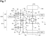
- Figures 6 to 8 illustrate an embodiment wherein the power take-off PTO is connected to the second electric motor EM2.
- Figure 6 illustrates an example wherein the power take-off PTO is located at the second extremity E22' of the tertiary shaft 54.
- Figure 7 illustrates an example wherein the power take-off PTO is located at the second extremity E2' of the motor shaft 15.
- a rational gear 28 arranged on the second extremity E2' of the motor shaft 15 is meshing with a gear 60 of the PTO.
- a coupling member, in particular a clutch may be located between the power take-off PTO and the motor shaft 15.
- the tertiary shaft 54 allows the motion of the power take-off PTO through the rational gear 19 meshing with the gear 60 of the power take-off.
- the second electric motor EM2 does not transfer torque to the secondary shaft 44 and therefore to the wheels W1, W2.
- the vehicle 1 is still be motioned by the electric motor EM1.
- the electric motor EM1 can still be mechanically linked to the secondary shaft 44 and therefore to the wheels W1, W2.
- the speed and the torque of the second electric motor EM2 is adapted perfectly to the power take-off PTO.
- the tertiary shaft 54 allows the motion of the power take-off PTO through the rational gear 19 meshing with the gear 60 of the power take-off.
- the second electric motor EM2 does not transfer torque to the secondary shaft 44 and therefore to the wheels W1, W2.
- the vehicle 1 is at standstill and the PTO can be driven by both electric motors EM1 and EM2.
- the second electric motor EM2 is connected to the wheels W1, W2 allowing the propulsion torque of the vehicle 1 and the motion of the power take-off PTO is allowed.
- the vehicle 1 and the power take-off PTO are simultaneously in motion.
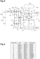
- Figure 9 shows all possible combinations provided by all the electric powertrain 2a, 2b and 2c.
- the column “cruise gear” represents the engagement status of the first coupling member 40.
- the second coupling member 18 (and the coupling member 55, if any) is or are preferably in neutral position.
- the coupling member 55 could be engaged in the first or second position while the cruise gear is engaged, i.e. while the first coupling member 40 is in engaged state.
- the combination 12 in Figure 9 allows a mechanical disconnection between vehicle wheels and electric motors. It can be used in downhill conditions for instance to avoid electric energy recuperation from the motors to the battery when this is not needed. It could also be used to avoid parasitic losses between all the elements of the electric powertrain and consequently allows energy saving. A full neutral position also allows to tow the truck in case of an unplanned stop since truck are usually tow with the driving wheel still touching the ground and rotating.
- EM2 and/or EM1 is(are) controlled by a control device (not shown), typical an ECU (not shown).
- EM2 and EM1 can be controlled simultaneously or independently from each other.
- the ECU may control both electric motors EM2, EM1 in a way that EM1 will provide required torque to the wheels whereas EM2 is switching gear and EM2 will provide required torque to the wheel whereas EM1 is switching gear.
- This configuration corresponds to a full powershift mode meaning that there is no torque interruption at all when switching gears. This full powershift effect allows better vehicle performance and enhances driving comfort.
- the transmission ratios of gearbox G23 are different from that of gearbox G12.
- the first speed ratio of G12 (“EM1 gear 1") is lower than the first speed ratio of G23 ("EM2 gear 2")
- the first speed ratio of G23 (“EM2 gear 2")
- the second speed ratio of G12 (“EM1 gear 3")
- the second speed ratio of G12 (“EM1 gear 3") is lower than the second speed ratio of G23 ("EM2 gear 4").
- the third speed ratio of G12, or “gear cruising ratio” is higher than the second speed ratio of G23 ("EM2 gear 4").
- the two gearboxes G12 and G23 form together a multi-input transmission, capable of selectively transmitting the torque of E-motor EM1 and the torque of E-motor EM2 (as inputs of the transmission) to the wheels, typically through the differential 10 (as output of the transmission).
- the present invention provides compact electric powertrains depending on the vehicle needs.
- the architecture of the electric powertrain is adapted to any kind of vehicle.
- the architecture of the electric powertrains according to the present invention is optimized to include a power take-off and offers a better efficiency. Consequently, the electric powertrains according to the present invention allow for a reduction of the production costs, an increased productivity and a better efficiency.
Landscapes
- Engineering & Computer Science (AREA)
- Mechanical Engineering (AREA)
- Chemical & Material Sciences (AREA)
- Combustion & Propulsion (AREA)
- Transportation (AREA)
- General Engineering & Computer Science (AREA)
- Gear Transmission (AREA)
- Electric Propulsion And Braking For Vehicles (AREA)
- Connection Of Motors, Electrical Generators, Mechanical Devices, And The Like (AREA)
Claims (13)
- Groupe motopropulseur électrique (2c) pour un véhicule (1), le groupe motopropulseur électrique (2c) étant configuré pour assurer la propulsion électrique du véhicule (1), dans lequel il comprend :- une unité de transmission comprenant un premier moteur électrique (EM1), un différentiel (10) et une boîte de vitesses (G12, G23) comprenant un premier module d'engrenages (G1), un deuxième module d'engrenages (G2),- le premier moteur électrique (EM1) étant relié au premier module d'engrenages (G1) par un arbre de moteur (14) présentant une première extrémité (E1) et une seconde extrémité (E2), ledit premier module d'engrenages (G1) comprenant un arbre primaire (34), présentant une première extrémité (E11) et une seconde extrémité (E22), sur lequel sont agencés un premier engrenage primaire (31), situé à sa première extrémité (E11), qui est fixé en rotation par rapport à l'arbre primaire (34), un deuxième engrenage primaire (32),- un deuxième module d'engrenages (G2) comprenant un arbre secondaire (44) sur lequel sont agencés un premier engrenage secondaire (41) qui s'engrène avec le premier engrenage primaire (31), un deuxième engrenage secondaire (42) s'engrenant avec le deuxième engrenage primaire (32),- un différentiel (10) relié au premier moteur électrique (EM1),ledit groupe motopropulseur électrique (2a) étant tel que le premier moteur électrique (EM1) relié au premier module d'engrenages (G1), et le deuxième module d'engrenages (G2) s'étendent parallèlement l'un à l'autre et qu'une prise de force (PTO) est raccordée au premier moteur électrique (EM1),le groupe motopropulseur électrique (2c) étant caractérisé en ce que :- l'unité de transmission comprend également un deuxième moteur électrique (EM2), la boîte de vitesses (G12, G23) comprenant également un troisième module d'engrenages (G3),- un troisième engrenage primaire (33) est situé à la seconde extrémité (E22) de l'arbre primaire (34) du premier module d'engrenages (G1),- un troisième engrenage secondaire (43) s'engrène avec le troisième engrenage primaire (33),- le deuxième moteur électrique (EM2) est relié au troisième module d'engrenages (G3) par un arbre de moteur (15) présentant une première extrémité (E1') et une seconde extrémité (E2'), ledit troisième module d'engrenages (G3) comprenant un arbre tertiaire (54), présentant une première extrémité (E11') et une seconde extrémité (E22'), sur lequel sont agencés un premier engrenage tertiaire (51) qui ne s'engrène avec aucun engrenage secondaire, ledit premier engrenage tertiaire (51) étant situé à sa première extrémité (E11'), un deuxième engrenage tertiaire (52) qui s'engrène avec le deuxième engrenage secondaire (42) et un troisième engrenage tertiaire (53) qui s'engrène avec le troisième engrenage secondaire (43), ledit troisième engrenage tertiaire (53) étant situé à sa seconde extrémité (E2'), un engrenage rotatif (17) s'engrenant avec le premier engrenage tertiaire (51) étant agencé sur la seconde extrémité (E2') de l'arbre de moteur (15), ledit deuxième engrenage tertiaire (42) et ledit troisième engrenage tertiaire (53) étant adjacents,- le différentiel (10) est partagé par les deux moteurs électriques (EM1, EM2),ledit groupe motopropulseur électrique (2c) étant tel que le premier moteur électrique (EM1) relié au premier module d'engrenages (G1), le deuxième module d'engrenages (G2) et le deuxième moteur électrique (EM2) relié au troisième module d'engrenages (G3) s'étendent parallèlement l'un à l'autre, et que la prise de force (PTO) est raccordée au premier moteur électrique (EM1) ou au deuxième moteur électrique (EM2).
- Groupe motopropulseur électrique (2a, 2c) pour un véhicule (1) selon la revendication 1, dans lequel la prise de force (PTO) est située à la seconde extrémité (E22) de l'arbre primaire (34).
- Groupe motopropulseur électrique (2a, 2c) pour un véhicule (1) selon la revendication 2, dans lequel un engrenage rationnel agencé sur la seconde extrémité (E22) de l'arbre primaire (34) s'engrène avec un engrenage de la PTO.
- Groupe motopropulseur électrique (2a, 2c) pour un véhicule (1) selon les revendications 1 à 3, dans lequel un moyen d'accouplement est situé entre la prise de force (PTO) et l'arbre primaire (34).
- Groupe motopropulseur électrique (2a, 2c) pour un véhicule (1) selon la revendication 1, dans lequel la prise de force (PTO) est située à la seconde extrémité (E2) de l'arbre de moteur (14).
- Groupe motopropulseur électrique (2a, 2c) pour un véhicule (1) selon la revendication 5, dans lequel un engrenage rationnel agencé sur la seconde extrémité (E2) de l'arbre de moteur (14) s'engrène avec un engrenage de la PTO.
- Groupe motopropulseur électrique (2a, 2c) pour un véhicule (1) selon la revendication 1, 5 ou 6, dans lequel un embrayage est situé entre la prise de force (PTO) et l'arbre de moteur (14).
- Groupe motopropulseur électrique (2b, 2c) pour un véhicule (1) selon la revendication 1, dans lequel la prise de force (PTO) est située à la seconde extrémité (E22') de l'arbre tertiaire (54).
- Groupe motopropulseur électrique (2b, 2c) pour un véhicule (1) selon la revendication 8, dans lequel un engrenage rationnel (19) agencé sur la seconde extrémité (E22') de l'arbre tertiaire (54) s'engrène avec un engrenage (60) de la PTO.
- Groupe motopropulseur électrique (2b, 2c) pour un véhicule (1) selon la revendication 1, 8 ou 9, dans lequel un élément d'accouplement (63) est situé entre la prise de force (PTO) et l'arbre tertiaire (54).
- Groupe motopropulseur électrique (2b, 2c) pour un véhicule (1) selon la revendication 1, dans lequel la prise de force (PTO) est située à la seconde extrémité (E2') de l'arbre de moteur (15).
- Groupe motopropulseur électrique (2b, 2c) pour un véhicule (1) selon la revendication 11, dans lequel un engrenage rationnel (28) agencé sur la seconde extrémité (E2') de l'arbre de moteur (15) s'engrène avec un engrenage (60) de la PTO.
- Groupe motopropulseur électrique (2b, 2c) pour un véhicule (1) selon la revendication 1, 11 ou 12, dans lequel un embrayage est situé entre la prise de force (PTO) et l'arbre de moteur (15).
Priority Applications (3)
| Application Number | Priority Date | Filing Date | Title |
|---|---|---|---|
| EP21184361.0A EP4116122B1 (fr) | 2021-07-07 | 2021-07-07 | Transmission électrique pour un véhicule |
| CN202210586043.7A CN115593213A (zh) | 2021-07-07 | 2022-05-27 | 用于车辆的电动力总成 |
| US17/808,904 US11890928B2 (en) | 2021-07-07 | 2022-06-24 | Electric powertrain for a vehicle |
Applications Claiming Priority (1)
| Application Number | Priority Date | Filing Date | Title |
|---|---|---|---|
| EP21184361.0A EP4116122B1 (fr) | 2021-07-07 | 2021-07-07 | Transmission électrique pour un véhicule |
Publications (2)
| Publication Number | Publication Date |
|---|---|
| EP4116122A1 EP4116122A1 (fr) | 2023-01-11 |
| EP4116122B1 true EP4116122B1 (fr) | 2025-07-09 |
Family
ID=76845009
Family Applications (1)
| Application Number | Title | Priority Date | Filing Date |
|---|---|---|---|
| EP21184361.0A Active EP4116122B1 (fr) | 2021-07-07 | 2021-07-07 | Transmission électrique pour un véhicule |
Country Status (3)
| Country | Link |
|---|---|
| US (1) | US11890928B2 (fr) |
| EP (1) | EP4116122B1 (fr) |
| CN (1) | CN115593213A (fr) |
Families Citing this family (5)
| Publication number | Priority date | Publication date | Assignee | Title |
|---|---|---|---|---|
| US11655863B1 (en) * | 2021-11-17 | 2023-05-23 | Dana Belgium N.V. | Electric driveline system with power take-off and electric driveline system operating method |
| EP4408691A4 (fr) * | 2022-12-22 | 2025-03-19 | Mahindra and Mahindra Limited | Groupe motopropulseur pour engin de chantier |
| US20240300325A1 (en) * | 2023-03-10 | 2024-09-12 | Dana Motion Systems Italia S.R.L. | Gearbox for a front axle of an electric tractor |
| US20250010709A1 (en) * | 2023-07-03 | 2025-01-09 | Flyer Next, LLC | Electric axle system with different gear ratios |
| DE102024207449A1 (de) * | 2024-08-06 | 2026-02-12 | Zf Friedrichshafen Ag | Verfahren zum Betreiben eines Antriebsstrangs, Antriebsstrang und Arbeitsmaschine |
Family Cites Families (32)
| Publication number | Priority date | Publication date | Assignee | Title |
|---|---|---|---|---|
| US8099204B2 (en) * | 2007-11-05 | 2012-01-17 | GM Global Technology Operatons LLC | Method for controlling electric boost in a hybrid powertrain |
| US8112207B2 (en) * | 2007-11-05 | 2012-02-07 | GM Global Technology Operations LLC | Method and apparatus to determine a preferred output torque for operating a hybrid transmission in a continuously variable mode |
| US8140230B2 (en) * | 2008-10-08 | 2012-03-20 | GM Global Technology Operations LLC | Apparatus and method for regulating active driveline damping in hybrid vehicle powertrain |
| DE102012208926B4 (de) * | 2012-05-29 | 2020-03-12 | Schaeffler Technologies AG & Co. KG | Elektroachse für ein Fahrzeug |
| US9650032B2 (en) * | 2015-02-17 | 2017-05-16 | Oshkosh Corporation | Multi-mode electromechanical variable transmission |
| US9656659B2 (en) * | 2015-02-17 | 2017-05-23 | Oshkosh Corporation | Multi-mode electromechanical variable transmission |
| DE102015206190A1 (de) | 2015-04-08 | 2016-10-13 | Bayerische Motoren Werke Aktiengesellschaft | Getriebevorrichtung und Schaltverfahren für eine Antriebsvorrichtung mit zwei elektrischen Maschinen |
| EP3580083B1 (fr) | 2017-02-08 | 2022-06-01 | Oshkosh Corporation | Unificateur de puissance pour deux moteurs |
| WO2018156676A2 (fr) | 2017-02-22 | 2018-08-30 | Dana Heavy Vehicle Systems Group, Llc | Essieux électriques à variation continue ayant des capacités de collecte d'énergie à la demande pour des essieux électriques secondaires ou traînés |
| DE102018203456B4 (de) * | 2018-03-07 | 2019-10-10 | Audi Ag | Antriebsvorrichtung für ein elektrisch betriebenes Fahrzeug |
| DE102018119488A1 (de) * | 2018-08-10 | 2020-02-13 | Schaeffler Technologies AG & Co. KG | Elektromechanische Antriebsanordnung für ein Kraftfahrzeug |
| DE102018213870A1 (de) * | 2018-08-17 | 2020-02-20 | Zf Friedrichshafen Ag | Leistungsverzweigtes Getriebe |
| DE102018215924A1 (de) * | 2018-09-19 | 2020-03-19 | ZF Drivetech (Suzhou) Co.Ltd. | Elektrische Antriebsachse für ein Fahrzeug |
| DE102018215932A1 (de) | 2018-09-19 | 2020-03-19 | ZF Drivetech (Suzhou) Co.Ltd. | Antriebsvorrichtung für eine elektrisch angetriebene Achse eines Kraftfahrzeugs |
| DE102018222257A1 (de) * | 2018-12-19 | 2020-06-25 | Zf Friedrichshafen Ag | Anordnung zum Antrieb einer Fahrzeugachse und Verfahren zum Betreiben der Antriebsanordnung |
| DE102018222251A1 (de) * | 2018-12-19 | 2020-06-25 | Zf Friedrichshafen Ag | Antriebsvorrichtung zum Antrieb einer Fahrzeugachse und Verfahren zum Betreiben der Antriebsvorrichtung |
| DE102019202207A1 (de) * | 2019-02-19 | 2020-08-20 | Zf Friedrichshafen Ag | Antriebsachse eines Elektrofahrzeuges |
| DE102019106294A1 (de) * | 2019-03-12 | 2020-09-17 | MULAG FAHRZEUGWERK Heinz Wössner GmbH & Co. KG | Voll-elektrische Antriebseinheit für ein Fahrzeug, insbesondere eine selbstfahrende Arbeitsmaschine, sowie Vorgehensweise zu ihrem Betrieb |
| WO2020197463A1 (fr) | 2019-03-28 | 2020-10-01 | Scania Cv Ab | Groupe motopropulseur pour un véhicule, véhicule tout électrique et procédé de commande d'un groupe motopropulseur |
| DE102019206957A1 (de) * | 2019-05-14 | 2020-11-19 | Zf Friedrichshafen Ag | Antriebsachse eines Elektrofahrzeuges |
| SE543431C2 (en) * | 2019-06-18 | 2021-02-16 | Scania Cv Ab | A powertrain for a vehicle |
| DE102019210511B4 (de) * | 2019-07-17 | 2023-12-07 | Zf Friedrichshafen Ag | Kraftfahrzeuggetriebe |
| KR20210013453A (ko) * | 2019-07-25 | 2021-02-04 | 현대자동차주식회사 | 하이브리드 차량용 동력전달장치 |
| US11247563B2 (en) * | 2020-05-22 | 2022-02-15 | Dana Belgium N.V. | Vehicle transmission with an inter-axle differential and method for operation of said inter-axle differential |
| CN114475192A (zh) * | 2020-10-27 | 2022-05-13 | 广州汽车集团股份有限公司 | 一种双电机动力总成及换挡控制方法 |
| US11235662B1 (en) * | 2020-11-02 | 2022-02-01 | GM Global Technology Operations LLC | Electrically propelled vehicle gearbox having a power take-off |
| KR20220120783A (ko) * | 2021-02-23 | 2022-08-31 | 현대자동차주식회사 | 전동화 차량의 파워트레인 |
| KR20220154999A (ko) * | 2021-05-14 | 2022-11-22 | 현대자동차주식회사 | 전동화 차량의 파워트레인 |
| DE102021208545A1 (de) * | 2021-08-06 | 2023-02-09 | Zf Friedrichshafen Ag | Getriebe für ein Fahrzeug sowie Antriebsstrang mit einem solchen Getriebe |
| DE102021208557A1 (de) * | 2021-08-06 | 2023-02-09 | Zf Friedrichshafen Ag | Getriebe und Antriebsstrang für ein Fahrzeug |
| CN114013263B (zh) * | 2021-12-22 | 2024-03-08 | 吉林大学 | 一种四模式双电机耦合电动驱动桥 |
| CN114523836B (zh) * | 2022-03-21 | 2022-12-16 | 南通大学 | 一种发动机-飞轮动力耦合系统的驱动方法 |
-
2021
- 2021-07-07 EP EP21184361.0A patent/EP4116122B1/fr active Active
-
2022
- 2022-05-27 CN CN202210586043.7A patent/CN115593213A/zh active Pending
- 2022-06-24 US US17/808,904 patent/US11890928B2/en active Active
Also Published As
| Publication number | Publication date |
|---|---|
| US20230011463A1 (en) | 2023-01-12 |
| EP4116122A1 (fr) | 2023-01-11 |
| CN115593213A (zh) | 2023-01-13 |
| US11890928B2 (en) | 2024-02-06 |
Similar Documents
| Publication | Publication Date | Title |
|---|---|---|
| US12179571B2 (en) | Electric powertrain for a vehicle | |
| EP4116122B1 (fr) | Transmission électrique pour un véhicule | |
| EP4077007B1 (fr) | Boîte de vitesses pour un groupe motopropulseur électrique | |
| US6527659B1 (en) | Two-mode input-compound split electromechanical transmission for front wheel drive vehicles | |
| EP3750728B1 (fr) | Système de groupe motopropulseur de véhicule | |
| CN114537111A (zh) | 一种双电机电驱动桥总成及车辆 | |
| CN110758082B (zh) | 一种新能源车辆动力耦合装置及其控制方法 | |
| CN110758083A (zh) | 一种新能源车辆动力系统及其控制方法 | |
| CN210174608U (zh) | 混合动力汽车及其动力系统和传动系统 | |
| CN219727845U (zh) | 一种双电机分布式电驱桥及车辆 | |
| US12337844B2 (en) | Method of oil pre-conditioning for an electric powertrain of a vehicle | |
| US12030377B2 (en) | Electric powertrain for a vehicle | |
| EP3936357A1 (fr) | Module d'entraînement électrique | |
| CN112477570A (zh) | 一种驱动合成装置以及电动车辆 | |
| CN118144552A (zh) | 用于车辆的动力传动系统以及车辆 | |
| CN114537126A (zh) | 车辆的动力系统 | |
| CN113602074A (zh) | 动力驱动系统以及车辆 | |
| CN220809120U (zh) | 混合动力车桥装置 | |
| US11879529B1 (en) | Gearbox for electric off-road vehicles | |
| CN119795891B (zh) | 车辆变速器和混合动力系统 | |
| CN110758081B (zh) | 一种新能源车辆动力系统的动力耦合装置及其控制方法 | |
| CN121229589A (zh) | 一种车用减速器总成及具有该车用减速器总成的双档混动系统和车辆 | |
| CN121697436A (zh) | 一种双电机混合动力总成装置及其控制方法 | |
| CN120963344A (zh) | 一种双档混动系统及具有该双档混动系统的车辆 | |
| CN120384937A (zh) | 用于车辆的变速器 |
Legal Events
| Date | Code | Title | Description |
|---|---|---|---|
| PUAI | Public reference made under article 153(3) epc to a published international application that has entered the european phase |
Free format text: ORIGINAL CODE: 0009012 |
|
| STAA | Information on the status of an ep patent application or granted ep patent |
Free format text: STATUS: THE APPLICATION HAS BEEN PUBLISHED |
|
| AK | Designated contracting states |
Kind code of ref document: A1 Designated state(s): AL AT BE BG CH CY CZ DE DK EE ES FI FR GB GR HR HU IE IS IT LI LT LU LV MC MK MT NL NO PL PT RO RS SE SI SK SM TR |
|
| STAA | Information on the status of an ep patent application or granted ep patent |
Free format text: STATUS: REQUEST FOR EXAMINATION WAS MADE |
|
| 17P | Request for examination filed |
Effective date: 20230622 |
|
| RBV | Designated contracting states (corrected) |
Designated state(s): AL AT BE BG CH CY CZ DE DK EE ES FI FR GB GR HR HU IE IS IT LI LT LU LV MC MK MT NL NO PL PT RO RS SE SI SK SM TR |
|
| STAA | Information on the status of an ep patent application or granted ep patent |
Free format text: STATUS: EXAMINATION IS IN PROGRESS |
|
| 17Q | First examination report despatched |
Effective date: 20241008 |
|
| GRAP | Despatch of communication of intention to grant a patent |
Free format text: ORIGINAL CODE: EPIDOSNIGR1 |
|
| STAA | Information on the status of an ep patent application or granted ep patent |
Free format text: STATUS: GRANT OF PATENT IS INTENDED |
|
| INTG | Intention to grant announced |
Effective date: 20250327 |
|
| GRAS | Grant fee paid |
Free format text: ORIGINAL CODE: EPIDOSNIGR3 |
|
| GRAA | (expected) grant |
Free format text: ORIGINAL CODE: 0009210 |
|
| STAA | Information on the status of an ep patent application or granted ep patent |
Free format text: STATUS: THE PATENT HAS BEEN GRANTED |
|
| AK | Designated contracting states |
Kind code of ref document: B1 Designated state(s): AL AT BE BG CH CY CZ DE DK EE ES FI FR GB GR HR HU IE IS IT LI LT LU LV MC MK MT NL NO PL PT RO RS SE SI SK SM TR |
|
| REG | Reference to a national code |
Ref country code: GB Ref legal event code: FG4D |
|
| REG | Reference to a national code |
Ref country code: CH Ref legal event code: EP |
|
| REG | Reference to a national code |
Ref country code: IE Ref legal event code: FG4D |
|
| REG | Reference to a national code |
Ref country code: DE Ref legal event code: R096 Ref document number: 602021033654 Country of ref document: DE |
|
| REG | Reference to a national code |
Ref country code: NL Ref legal event code: MP Effective date: 20250709 |
|
| PG25 | Lapsed in a contracting state [announced via postgrant information from national office to epo] |
Ref country code: PT Free format text: LAPSE BECAUSE OF FAILURE TO SUBMIT A TRANSLATION OF THE DESCRIPTION OR TO PAY THE FEE WITHIN THE PRESCRIBED TIME-LIMIT Effective date: 20251110 |
|
| PG25 | Lapsed in a contracting state [announced via postgrant information from national office to epo] |
Ref country code: NL Free format text: LAPSE BECAUSE OF FAILURE TO SUBMIT A TRANSLATION OF THE DESCRIPTION OR TO PAY THE FEE WITHIN THE PRESCRIBED TIME-LIMIT Effective date: 20250709 |
|
| REG | Reference to a national code |
Ref country code: AT Ref legal event code: MK05 Ref document number: 1811558 Country of ref document: AT Kind code of ref document: T Effective date: 20250709 |
|
| PG25 | Lapsed in a contracting state [announced via postgrant information from national office to epo] |
Ref country code: IS Free format text: LAPSE BECAUSE OF FAILURE TO SUBMIT A TRANSLATION OF THE DESCRIPTION OR TO PAY THE FEE WITHIN THE PRESCRIBED TIME-LIMIT Effective date: 20251109 |
|
| PG25 | Lapsed in a contracting state [announced via postgrant information from national office to epo] |
Ref country code: NO Free format text: LAPSE BECAUSE OF FAILURE TO SUBMIT A TRANSLATION OF THE DESCRIPTION OR TO PAY THE FEE WITHIN THE PRESCRIBED TIME-LIMIT Effective date: 20251009 |
|
| REG | Reference to a national code |
Ref country code: LT Ref legal event code: MG9D |
|
| PG25 | Lapsed in a contracting state [announced via postgrant information from national office to epo] |
Ref country code: AT Free format text: LAPSE BECAUSE OF FAILURE TO SUBMIT A TRANSLATION OF THE DESCRIPTION OR TO PAY THE FEE WITHIN THE PRESCRIBED TIME-LIMIT Effective date: 20250709 |
|
| PG25 | Lapsed in a contracting state [announced via postgrant information from national office to epo] |
Ref country code: FI Free format text: LAPSE BECAUSE OF FAILURE TO SUBMIT A TRANSLATION OF THE DESCRIPTION OR TO PAY THE FEE WITHIN THE PRESCRIBED TIME-LIMIT Effective date: 20250709 |
|
| PG25 | Lapsed in a contracting state [announced via postgrant information from national office to epo] |
Ref country code: HR Free format text: LAPSE BECAUSE OF FAILURE TO SUBMIT A TRANSLATION OF THE DESCRIPTION OR TO PAY THE FEE WITHIN THE PRESCRIBED TIME-LIMIT Effective date: 20250709 |
|
| PG25 | Lapsed in a contracting state [announced via postgrant information from national office to epo] |
Ref country code: GR Free format text: LAPSE BECAUSE OF FAILURE TO SUBMIT A TRANSLATION OF THE DESCRIPTION OR TO PAY THE FEE WITHIN THE PRESCRIBED TIME-LIMIT Effective date: 20251010 |
|
| PG25 | Lapsed in a contracting state [announced via postgrant information from national office to epo] |
Ref country code: SE Free format text: LAPSE BECAUSE OF FAILURE TO SUBMIT A TRANSLATION OF THE DESCRIPTION OR TO PAY THE FEE WITHIN THE PRESCRIBED TIME-LIMIT Effective date: 20250709 |
|
| PG25 | Lapsed in a contracting state [announced via postgrant information from national office to epo] |
Ref country code: LV Free format text: LAPSE BECAUSE OF FAILURE TO SUBMIT A TRANSLATION OF THE DESCRIPTION OR TO PAY THE FEE WITHIN THE PRESCRIBED TIME-LIMIT Effective date: 20250709 |
|
| PG25 | Lapsed in a contracting state [announced via postgrant information from national office to epo] |
Ref country code: PL Free format text: LAPSE BECAUSE OF FAILURE TO SUBMIT A TRANSLATION OF THE DESCRIPTION OR TO PAY THE FEE WITHIN THE PRESCRIBED TIME-LIMIT Effective date: 20250709 Ref country code: BG Free format text: LAPSE BECAUSE OF FAILURE TO SUBMIT A TRANSLATION OF THE DESCRIPTION OR TO PAY THE FEE WITHIN THE PRESCRIBED TIME-LIMIT Effective date: 20250709 |
|
| PG25 | Lapsed in a contracting state [announced via postgrant information from national office to epo] |
Ref country code: RS Free format text: LAPSE BECAUSE OF FAILURE TO SUBMIT A TRANSLATION OF THE DESCRIPTION OR TO PAY THE FEE WITHIN THE PRESCRIBED TIME-LIMIT Effective date: 20251009 |
|
| PG25 | Lapsed in a contracting state [announced via postgrant information from national office to epo] |
Ref country code: ES Free format text: LAPSE BECAUSE OF FAILURE TO SUBMIT A TRANSLATION OF THE DESCRIPTION OR TO PAY THE FEE WITHIN THE PRESCRIBED TIME-LIMIT Effective date: 20250709 |
|
| PG25 | Lapsed in a contracting state [announced via postgrant information from national office to epo] |
Ref country code: SM Free format text: LAPSE BECAUSE OF FAILURE TO SUBMIT A TRANSLATION OF THE DESCRIPTION OR TO PAY THE FEE WITHIN THE PRESCRIBED TIME-LIMIT Effective date: 20250709 |
|
| PG25 | Lapsed in a contracting state [announced via postgrant information from national office to epo] |
Ref country code: DK Free format text: LAPSE BECAUSE OF FAILURE TO SUBMIT A TRANSLATION OF THE DESCRIPTION OR TO PAY THE FEE WITHIN THE PRESCRIBED TIME-LIMIT Effective date: 20250709 |
|
| PG25 | Lapsed in a contracting state [announced via postgrant information from national office to epo] |
Ref country code: IT Free format text: LAPSE BECAUSE OF FAILURE TO SUBMIT A TRANSLATION OF THE DESCRIPTION OR TO PAY THE FEE WITHIN THE PRESCRIBED TIME-LIMIT Effective date: 20250709 |