EP4116169A1 - Dreipunktauflagevorrichtung, entsprechendes fahrzeug und entsprechende zuggarnitur - Google Patents
Dreipunktauflagevorrichtung, entsprechendes fahrzeug und entsprechende zuggarnitur Download PDFInfo
- Publication number
- EP4116169A1 EP4116169A1 EP22182728.0A EP22182728A EP4116169A1 EP 4116169 A1 EP4116169 A1 EP 4116169A1 EP 22182728 A EP22182728 A EP 22182728A EP 4116169 A1 EP4116169 A1 EP 4116169A1
- Authority
- EP
- European Patent Office
- Prior art keywords
- suspension
- central
- bogie
- emergency
- support
- Prior art date
- Legal status (The legal status is an assumption and is not a legal conclusion. Google has not performed a legal analysis and makes no representation as to the accuracy of the status listed.)
- Pending
Links
Images


Classifications
-
- B—PERFORMING OPERATIONS; TRANSPORTING
- B61—RAILWAYS
- B61F—RAIL VEHICLE SUSPENSIONS, e.g. UNDERFRAMES, BOGIES OR ARRANGEMENTS OF WHEEL AXLES; RAIL VEHICLES FOR USE ON TRACKS OF DIFFERENT WIDTH; PREVENTING DERAILING OF RAIL VEHICLES; WHEEL GUARDS, OBSTRUCTION REMOVERS OR THE LIKE FOR RAIL VEHICLES
- B61F5/00—Constructional details of bogies; Connections between bogies and vehicle underframes; Arrangements or devices for adjusting or allowing self-adjustment of wheel axles or bogies when rounding curves
- B61F5/02—Arrangements permitting limited transverse relative movements between vehicle underframe or bolster and bogie; Connections between underframes and bogies
- B61F5/22—Guiding of the vehicle underframes with respect to the bogies
-
- B—PERFORMING OPERATIONS; TRANSPORTING
- B61—RAILWAYS
- B61F—RAIL VEHICLE SUSPENSIONS, e.g. UNDERFRAMES, BOGIES OR ARRANGEMENTS OF WHEEL AXLES; RAIL VEHICLES FOR USE ON TRACKS OF DIFFERENT WIDTH; PREVENTING DERAILING OF RAIL VEHICLES; WHEEL GUARDS, OBSTRUCTION REMOVERS OR THE LIKE FOR RAIL VEHICLES
- B61F5/00—Constructional details of bogies; Connections between bogies and vehicle underframes; Arrangements or devices for adjusting or allowing self-adjustment of wheel axles or bogies when rounding curves
- B61F5/02—Arrangements permitting limited transverse relative movements between vehicle underframe or bolster and bogie; Connections between underframes and bogies
- B61F5/04—Bolster supports or mountings
- B61F5/08—Bolster supports or mountings incorporating rubber springs
-
- B—PERFORMING OPERATIONS; TRANSPORTING
- B61—RAILWAYS
- B61F—RAIL VEHICLE SUSPENSIONS, e.g. UNDERFRAMES, BOGIES OR ARRANGEMENTS OF WHEEL AXLES; RAIL VEHICLES FOR USE ON TRACKS OF DIFFERENT WIDTH; PREVENTING DERAILING OF RAIL VEHICLES; WHEEL GUARDS, OBSTRUCTION REMOVERS OR THE LIKE FOR RAIL VEHICLES
- B61F5/00—Constructional details of bogies; Connections between bogies and vehicle underframes; Arrangements or devices for adjusting or allowing self-adjustment of wheel axles or bogies when rounding curves
- B61F5/02—Arrangements permitting limited transverse relative movements between vehicle underframe or bolster and bogie; Connections between underframes and bogies
- B61F5/04—Bolster supports or mountings
- B61F5/10—Bolster supports or mountings incorporating fluid springs
-
- B—PERFORMING OPERATIONS; TRANSPORTING
- B61—RAILWAYS
- B61F—RAIL VEHICLE SUSPENSIONS, e.g. UNDERFRAMES, BOGIES OR ARRANGEMENTS OF WHEEL AXLES; RAIL VEHICLES FOR USE ON TRACKS OF DIFFERENT WIDTH; PREVENTING DERAILING OF RAIL VEHICLES; WHEEL GUARDS, OBSTRUCTION REMOVERS OR THE LIKE FOR RAIL VEHICLES
- B61F5/00—Constructional details of bogies; Connections between bogies and vehicle underframes; Arrangements or devices for adjusting or allowing self-adjustment of wheel axles or bogies when rounding curves
- B61F5/02—Arrangements permitting limited transverse relative movements between vehicle underframe or bolster and bogie; Connections between underframes and bogies
- B61F5/16—Centre bearings or other swivel connections between underframes and bolsters or bogies
-
- B—PERFORMING OPERATIONS; TRANSPORTING
- B61—RAILWAYS
- B61F—RAIL VEHICLE SUSPENSIONS, e.g. UNDERFRAMES, BOGIES OR ARRANGEMENTS OF WHEEL AXLES; RAIL VEHICLES FOR USE ON TRACKS OF DIFFERENT WIDTH; PREVENTING DERAILING OF RAIL VEHICLES; WHEEL GUARDS, OBSTRUCTION REMOVERS OR THE LIKE FOR RAIL VEHICLES
- B61F5/00—Constructional details of bogies; Connections between bogies and vehicle underframes; Arrangements or devices for adjusting or allowing self-adjustment of wheel axles or bogies when rounding curves
- B61F5/50—Other details
- B61F5/52—Bogie frames
Definitions
- a railway vehicle generally comprises a body resting on bogies.
- each body is conventionally supported on two bogies.
- the trainset is non-articulated and all the vehicles of the trainset are vehicles whose body is supported by a device 30 with three support points.
- the train is articulated and at least the key car of the train (car supported by two bogies) is supported by a device 30 with three support points.
- the key car is, for example, an end vehicle of the train, advantageously the lead vehicle of the train.
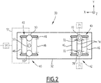
- the device 30 comprises a first bogie 40 and a second bogie 42.
- the first bogie 40 and the second bogie 42 are the only bogies of the device 30, and thus the only bogies supporting the body 32.
- Each of the first bogie 40 and the second bogie 42 is motorized or not.
- Each of the first bogie 40 and the second bogie 42 comprises a frame 43, two axles 46 each having two wheels 48 (only a reference 48 is shown on the figure 2 so as not to overload the figure).
- the first bogie 40 is able to support the body 32 by a first point of support.
- the first bogie 40 comprises two first secondary pneumatic suspensions 50 and a central emergency suspension 52.
- the first secondary air suspensions 50 are pneumatically connected to each other, for example, by a pneumatic pipe or tube 51 (shown in dotted lines on the figure 2 ).
- the first secondary pneumatic suspensions 50 therefore have substantially the same air pressure under normal operating conditions.
- the first secondary pneumatic suspensions 50 are for example supplied via a regulation component 54.
- the regulation component 54 is suitable for regulating the air pressure in the first secondary pneumatic suspensions 50, in particular according to the load of the body 32 supported by the first bogie 40.
- Such a regulation component 54 allows inflation (air injection from an air compressor) or deflation (exhaust to the outside—ambient air).
- the regulation component 54 is arranged on or in the frame 43 on the central longitudinal axis X B .
- the regulating component 54 is, for example, a leveling valve.
- the leveling valve is, for example, mechanically actuated.
- control component 54 is a solenoid valve.
- the solenoid valve is, for example, controlled by a position sensor measuring the distance between the first bogie 40 and the body 32.
- the central emergency suspension 52 is suitable for replacing the first secondary pneumatic suspensions 50 when said first suspensions 50 are dysfunctional.
- the central emergency suspension 52 is the only emergency suspension of the first bogie 40.
- the central emergency suspension 52 comprises two emergency elements 60 arranged on the central longitudinal axis X B on either side of the central pivot 49.
- each emergency element 60 comprises an elastic member 61, a fixing plate 62 and a support element 63.
- the elastic member 61 has a spring function.
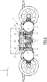
- the elastic member 61 is capable of being fixed, via the fixing plate 62, either to the body 32 (as illustrated by the figure 4 ), or to the bogie.
- the support element 63 is fixed on the side opposite the elastic member 61, that is to say is fixed on the first bogie 40 when the elastic member 61 is fixed on the body 32 (as illustrated by the figure 4 ) or is fixed on the body 32 when the elastic member 61 is fixed on the first bogie 40.
- the support element 63 is fixed on the bogie, it is for example fixed directly on the bogie frame 43 or on any element itself fixed to the bogie frame 43.
- the first bogie 72 is a motor bogie as is the case on the figure 3 and 4
- the support element 63 is fixed to the motor 69 which is itself fixed to the bogie frame 43.
- the support element 63 is preferably made of a material chosen to reduce the coefficient of friction and have good anti-wear properties.
- the material of the support element 63 is, for example, a Teflon® -coated metal or a nylon-type polymer, such as Ertalon® .
- An operating clearance 64 is present between the elastic member 61 and the support element 63, which allows the corresponding secondary pneumatic suspension 50 to be the only one in operation when this secondary pneumatic suspension 50 is inflated (normal mode ). In the event of damage (degraded mode), the secondary pneumatic suspension 50 is no longer active and the operating clearance 64 between the elastic member 61 and the support element 63 is filled so that the emergency element 60 replaces said secondary air suspension 50.
- FIG. 3 and 4 describe a central emergency suspension 52 with two emergency elements 60, in a variant, only one emergency element 60 is present.
- Such an emergency element 60 is, for example, arranged upstream or downstream of the central pivot 49 on the central longitudinal axis X B .
- a two-way arrangement relief elements 60 nevertheless have the advantage of being more stable compared to an arrangement with a single relief element 60, and of distributing the forces over a doubled support surface.
- the first fulcrum is formed by the first two secondary pneumatic suspensions 50 pneumatically connected or by the emergency central suspension 52 when the first secondary pneumatic suspensions 50 are dysfunctional.
- the second bogie 42 comprises two second secondary pneumatic suspensions 70.
- the second secondary pneumatic suspensions 70 are the only secondary suspensions of the second bogie 42.
- the second secondary pneumatic suspensions 70 are suspensions arranged on the frame 43 on either side of the central longitudinal axis X B .
- Each second secondary air suspension 70 is associated with a separate control component 71 (shown in dotted lines on the figure 2 for information) suitable for regulating the air pressure in said second secondary pneumatic suspension 70 and a separate emergency lateral suspension 72.
- Each emergency lateral suspension 72 comprises, for example, an emergency foot, such as a rubber and metal foot.
- the second bogie 42 comprises an anti-roll system comprising one or two anti-roll bars 74.
- the stiffness of the bar(s) 74 of the anti-roll system is, for example, chosen so as to compensate for the absence of an anti-roll system on the first bogie. 40.
- Each of the second and the third support point is formed by a separate second secondary pneumatic suspension 70 or by the emergency lateral suspension 72 associated with said second secondary pneumatic suspension 70 when said second secondary pneumatic suspension 70 is dysfunctional.
- the first support point is formed by the first secondary pneumatic suspensions 50 connected to each other, and the second and the third support point are formed by each second secondary pneumatic suspensions 70.
- the first support point is formed by the emergency central suspension 52, and the second and the third support point are formed by each of the second secondary pneumatic suspensions 70.
- the first fulcrum is formed by the first secondary pneumatic suspensions 50 connected to each other, and each of the second and the third fulcrum is formed by a second separate secondary pneumatic suspension 70 or by the emergency lateral suspension 72 associated with said second secondary pneumatic suspension 70 when said second secondary pneumatic suspension 70 is dysfunctional.
- the first point of support is formed by the central emergency suspension 52, and each of the second and the third point of support is formed by a second separate secondary pneumatic suspension 70 or by the emergency lateral suspension 72 associated with said second secondary air suspension 70 when said second secondary air suspension 70 is dysfunctional.
- a safety valve is present between the second secondary pneumatic suspensions 70, making it possible to deflate a second secondary pneumatic suspension 70 in the event that the other second secondary pneumatic suspension 70 is dysfunctional.
- the other second secondary pneumatic suspension 70 is also rendered dysfunctional, and the supports are formed by the two emergency lateral suspensions 72 on each side.
- the device 30 has three points of support for the body 32 supported by the device 30.
- the pneumatic communication between the first two secondary pneumatic suspensions 50 allows by air transfer to eliminate the roll stiffness normally provided by independent secondary suspensions. This is all the more true in the preferred configuration where the first bogie 40 does not include an anti-roll device.
- the first bogie 40 forms a central point of support both in the normal operating mode and in the emergency operating mode.
- Such a configuration with three support points is called isostatic.
- Such a device 30 with three support points is particularly suitable for driving on tracks having geometric defects, in particular long or short twists and turns, which improves the safety of the vehicle. In particular, with such a configuration, the effects of body torsion and wheel unloading are reduced.
- the body 32 is held in roll only by the second bogie 42, which limits the torsion of the body 32 and facilitates passage over tracks having geometric defects.
- such a device 30 is relatively simple to implement insofar as the second bogie 42 is, for example, a conventional bogie and where no optimization of the primary suspensions is required.
- the first bogie 40 is directly derived from the second bogie 42 by simple adaptation (emergency suspension, pneumatic piping, anti-roll bar not fitted).
- the support device 30 makes it possible to cross large track bends while remaining on a technology of basic primary suspensions, for example rubber-metal conical studs.
- the support device 30 also makes it possible to simplify the adjustment of the "leveling" of the body, that is to say the adjustment of the horizontality of the body.
- Such a setting allows, for example, to have good door threshold heights on each side / at each of the doors, which is more complicated to achieve with a hyperstatic four-point assembly and four control components.
Landscapes
- Engineering & Computer Science (AREA)
- Mechanical Engineering (AREA)
- Vehicle Body Suspensions (AREA)
Applications Claiming Priority (1)
| Application Number | Priority Date | Filing Date | Title |
|---|---|---|---|
| FR2107251A FR3124785B1 (fr) | 2021-07-05 | 2021-07-05 | Dispositif d’appui à trois points, véhicule et rame associés |
Publications (1)
| Publication Number | Publication Date |
|---|---|
| EP4116169A1 true EP4116169A1 (de) | 2023-01-11 |
Family
ID=78536283
Family Applications (1)
| Application Number | Title | Priority Date | Filing Date |
|---|---|---|---|
| EP22182728.0A Pending EP4116169A1 (de) | 2021-07-05 | 2022-07-04 | Dreipunktauflagevorrichtung, entsprechendes fahrzeug und entsprechende zuggarnitur |
Country Status (2)
| Country | Link |
|---|---|
| EP (1) | EP4116169A1 (de) |
| FR (1) | FR3124785B1 (de) |
Citations (6)
| Publication number | Priority date | Publication date | Assignee | Title |
|---|---|---|---|---|
| US3738680A (en) * | 1970-04-09 | 1973-06-12 | Knorr Bremse Gmbh | Pneumatic suspension system for vehicles |
| US4665835A (en) * | 1984-03-01 | 1987-05-19 | M.A.N. Maschinenfabrik Augsburg-Nurnberg Aktiengesellschaft | Arrangement to increase roll stability of rail vehicles with air suspension |
| FR2605276A1 (fr) * | 1986-10-17 | 1988-04-22 | Alsthom | Dispositif de butee de secours pour suspension secondaire pneumatique de vehicule a bogies |
| JP2001334937A (ja) * | 2000-05-25 | 2001-12-04 | Yutaka Hayashi | 空気ばね内圧制御装置 |
| BRPI0900283A2 (pt) * | 2009-02-04 | 2010-10-26 | Univ Sao Paulo | sistema de amortecimento de rolagem e torção de suspensão de veìculo |
| WO2015135587A1 (en) * | 2014-03-14 | 2015-09-17 | Universite Catholique De Louvain | Pneumatic vehicle suspension, vehicle provided with such a suspension and method for retrofitting a vehicle suspension |
-
2021
- 2021-07-05 FR FR2107251A patent/FR3124785B1/fr active Active
-
2022
- 2022-07-04 EP EP22182728.0A patent/EP4116169A1/de active Pending
Patent Citations (6)
| Publication number | Priority date | Publication date | Assignee | Title |
|---|---|---|---|---|
| US3738680A (en) * | 1970-04-09 | 1973-06-12 | Knorr Bremse Gmbh | Pneumatic suspension system for vehicles |
| US4665835A (en) * | 1984-03-01 | 1987-05-19 | M.A.N. Maschinenfabrik Augsburg-Nurnberg Aktiengesellschaft | Arrangement to increase roll stability of rail vehicles with air suspension |
| FR2605276A1 (fr) * | 1986-10-17 | 1988-04-22 | Alsthom | Dispositif de butee de secours pour suspension secondaire pneumatique de vehicule a bogies |
| JP2001334937A (ja) * | 2000-05-25 | 2001-12-04 | Yutaka Hayashi | 空気ばね内圧制御装置 |
| BRPI0900283A2 (pt) * | 2009-02-04 | 2010-10-26 | Univ Sao Paulo | sistema de amortecimento de rolagem e torção de suspensão de veìculo |
| WO2015135587A1 (en) * | 2014-03-14 | 2015-09-17 | Universite Catholique De Louvain | Pneumatic vehicle suspension, vehicle provided with such a suspension and method for retrofitting a vehicle suspension |
Also Published As
| Publication number | Publication date |
|---|---|
| FR3124785A1 (fr) | 2023-01-06 |
| FR3124785B1 (fr) | 2025-04-25 |
Similar Documents
| Publication | Publication Date | Title |
|---|---|---|
| CA2683119C (fr) | Vehicule ferroviaire comprenant des bogies d'extremite pivotants | |
| EP2676859B1 (de) | Drehgestell eines Schienenfahrzeugs mit verbesserten Aufhängungen, insbesondere für eine Niederflur-Straßenbahn | |
| EP2134583B1 (de) | Primäraufhängung für ein drehgestell eines schienenfahrzeugs | |
| FR3029879A1 (fr) | Bogie motorise pour un vehicule ferroviaire a plancher surbaisse | |
| FR3042768A1 (fr) | Vehicule ferroviaire comprenant au moins un bogie abaisse | |
| FR2513583A1 (fr) | Bogie a orientation forcee pour vehicule ferroviaire | |
| FR3042769B1 (fr) | Vehicule ferroviaire comprenant au moins un bogie abaisse | |
| BE494018A (de) | ||
| EP4116169A1 (de) | Dreipunktauflagevorrichtung, entsprechendes fahrzeug und entsprechende zuggarnitur | |
| FR3118446A1 (fr) | Suspension pour vehicule ferroviaire a deux essieux | |
| FR2560575A1 (fr) | Dispositif ameliorant la stabilite au roulis de vehicules de chemin de fer a suspension pneumatique | |
| EP3222486B1 (de) | Schienenfahrzeugdrehgestell, das ein abgesenktes fahrgestell umfasst | |
| EP0035443A1 (de) | Aufhängung eines Eisenbahnfahrgestellrahmens an zumindest zwei Achsen und mit dieser Aufhängung versehener Fahrgestellrahmen | |
| EP4116165B1 (de) | Kette von sattelschlepperfahrzeugen und entsprechende gelenkzuggarnitur | |
| FR2970457A1 (fr) | Bogie de vehicule ferroviaire suspendu | |
| EP0277059B1 (de) | Schienenfahrzeug mit Lastverteilung auf die vier bezüglich des Aufbaus einstellbaren Achsen | |
| FR3049252A1 (fr) | Bogie comprenant une liaison rigide entre les boites d'essieu, et vehicule ferroviaire associe | |
| EP3225497B1 (de) | Verbindungseinheit zwischen einer fahrzeugkarosserie und einem drehgestellrahmen, und schienenfahrzeug, das eine solche verbindungseinheit umfasst | |
| EP3042821B1 (de) | Drehgestell, das eine zentralisierte primärfederung umfasst | |
| FR2572348A1 (fr) | Ensemble d'essieu orientable guide pour vehicules sur rails | |
| FR3106557A1 (fr) | Bogie pour véhicule à roues indépendantes et véhicule associé | |
| EP3521129B1 (de) | Drehgestell und entsprechendes schienenfahrzeug | |
| FR2491850A1 (fr) | Bogie de chemin de fer autodirecteur | |
| FR2937904A1 (fr) | Vehicule comprenant un essieu rigide monte pivotant sur un support mobile verticalement par rapport au chassis. | |
| BE507342A (de) |
Legal Events
| Date | Code | Title | Description |
|---|---|---|---|
| PUAI | Public reference made under article 153(3) epc to a published international application that has entered the european phase |
Free format text: ORIGINAL CODE: 0009012 |
|
| STAA | Information on the status of an ep patent application or granted ep patent |
Free format text: STATUS: THE APPLICATION HAS BEEN PUBLISHED |
|
| STAA | Information on the status of an ep patent application or granted ep patent |
Free format text: STATUS: REQUEST FOR EXAMINATION WAS MADE |
|
| AK | Designated contracting states |
Kind code of ref document: A1 Designated state(s): AL AT BE BG CH CY CZ DE DK EE ES FI FR GB GR HR HU IE IS IT LI LT LU LV MC MK MT NL NO PL PT RO RS SE SI SK SM TR |
|
| 17P | Request for examination filed |
Effective date: 20221221 |
|
| RBV | Designated contracting states (corrected) |
Designated state(s): AL AT BE BG CH CY CZ DE DK EE ES FI FR GB GR HR HU IE IS IT LI LT LU LV MC MK MT NL NO PL PT RO RS SE SI SK SM TR |
|
| RIN1 | Information on inventor provided before grant (corrected) |
Inventor name: COSTES, CYRIL |
|
| P01 | Opt-out of the competence of the unified patent court (upc) registered |
Effective date: 20230822 |
|
| STAA | Information on the status of an ep patent application or granted ep patent |
Free format text: STATUS: EXAMINATION IS IN PROGRESS |
|
| 17Q | First examination report despatched |
Effective date: 20240709 |
|
| GRAP | Despatch of communication of intention to grant a patent |
Free format text: ORIGINAL CODE: EPIDOSNIGR1 |
|
| STAA | Information on the status of an ep patent application or granted ep patent |
Free format text: STATUS: GRANT OF PATENT IS INTENDED |
|
| INTG | Intention to grant announced |
Effective date: 20260102 |
|
| GRAS | Grant fee paid |
Free format text: ORIGINAL CODE: EPIDOSNIGR3 |
|
| GRAA | (expected) grant |
Free format text: ORIGINAL CODE: 0009210 |
|
| STAA | Information on the status of an ep patent application or granted ep patent |
Free format text: STATUS: THE PATENT HAS BEEN GRANTED |