EP4116237A1 - Fördersystem, motorwalzensteuergerät und verfahren zum betrieb eines fördersystems - Google Patents
Fördersystem, motorwalzensteuergerät und verfahren zum betrieb eines fördersystems Download PDFInfo
- Publication number
- EP4116237A1 EP4116237A1 EP21184049.1A EP21184049A EP4116237A1 EP 4116237 A1 EP4116237 A1 EP 4116237A1 EP 21184049 A EP21184049 A EP 21184049A EP 4116237 A1 EP4116237 A1 EP 4116237A1
- Authority
- EP
- European Patent Office
- Prior art keywords
- motor
- controller
- roller
- merger
- diverter
- Prior art date
- Legal status (The legal status is an assumption and is not a legal conclusion. Google has not performed a legal analysis and makes no representation as to the accuracy of the status listed.)
- Pending
Links
Images


Classifications
-
- B—PERFORMING OPERATIONS; TRANSPORTING
- B65—CONVEYING; PACKING; STORING; HANDLING THIN OR FILAMENTARY MATERIAL
- B65G—TRANSPORT OR STORAGE DEVICES, e.g. CONVEYORS FOR LOADING OR TIPPING, SHOP CONVEYOR SYSTEMS OR PNEUMATIC TUBE CONVEYORS
- B65G13/00—Roller-ways
- B65G13/02—Roller-ways having driven rollers
- B65G13/06—Roller driving means
-
- B—PERFORMING OPERATIONS; TRANSPORTING
- B65—CONVEYING; PACKING; STORING; HANDLING THIN OR FILAMENTARY MATERIAL
- B65G—TRANSPORT OR STORAGE DEVICES, e.g. CONVEYORS FOR LOADING OR TIPPING, SHOP CONVEYOR SYSTEMS OR PNEUMATIC TUBE CONVEYORS
- B65G43/00—Control devices, e.g. for safety, warning or fault-correcting
- B65G43/10—Sequence control of conveyors operating in combination
Definitions
- the subject matter relates to a conveyor system, for instance for conveying goods, packages and the like.
- the subject matter in particular relates to a conveyor system with motor-driven conveyors driven by motor rollers.
- the subject matter also relates to a method for operating such a conveyor system.
- Motor-driven conveyor-rollers a.k.a. motor rollers
- the roller body usually is a hollow tube.
- the motor is arranged within the roller body.
- the motor is an electric motor which is configured to generate a rotational movement about the roller axis between an axle element and the roller body.
- motor roller can be used for the motor within the roller body alone, a drive unit comprising the motor and a corresponding control circuit for the motor within the roller body or the roller body comprising the motor and/or the drive unit.
- motor can be used for the motor as such as well as the drive unit comprising the motor as such and a corresponding control circuit for the motor.
- motor-rollers are operated by a control unit, also known as controller, being arranged external, outside the roller body.
- controller exchanges control signals with the motor inside the roller body.
- Motor-driven conveyors driven by motor-rollers of this type are used in conveyor systems.
- a single motor rollers is used to operate several roller bodies within a conveyor zone.
- Conveyor systems oftentimes have several conveyor zones through which an object to be conveyed passes one after the other. As has been said, within each conveyor zone, at least one motor-driven conveyor-roller operates several rollers.
- a motor-roller controller (also controller) has a wired power inlet for receiving electric power, preferably DC-power. Moreover, the controller has a wired motor roller port.
- the wired motor roller port is configured to provide the motor roller with drive power.
- the motor can be fed through the motor roller port using for instance a PWM-signal to control at least the rotational speed of the motor.
- status information and control signals can be exchanged between the motor roller and the controller using the motor roller port.
- Status information and/or control signals can, inter alia, include current motor speed, set motor speed, current conveyor speed, set conveyor speed, current rotational direction, set rotational direction, current/set operation mode, temperature, error messages, gear ratio of the motor gear, serial number, article number, production date etc.
- the motor roller port is a four wired motor port in line with EP 3 100 340 B1 .
- a conventional controller comprises a wired I/O (Input/Output)-port.
- This I/O-port is configured to exchange control information with a central control center for instance a central SPS.
- the I/O-port can, for instance, be configured using a proprietary protocol.
- the I/O-port can also be configured using standardized I/O-protocols, for instance according to CAN, DeviceNet, Ethernet Powerlink, INTERBUS, Fieldbus, LIN, M-Bus, PROFIBUS, VARAN etc.
- a wireless controller is know, which operates similar to the wired controller.
- the explanation for the wired and the wireless controllers can be used for both, with the exception that the I/O Bus of the wireless controller is a wireless bus, with appropriate wireless protocols.
- the controller is configured to exchange motor roller control signals with a motor roller at the motor roller port, to exchange motor roller status signals with the motor roller at the motor roller port and to exchange motor roller control signals for the motor roller with a central control at the I/O-port. Exchange of the relevant control and status signals are well known and need no further description. It should be noted that all of the ports and inlets of the wired controller are preferably wired ports, requiring wiring between the motor roller and the controller and between the controller and centralized control center. Wiring usually is necessary to provide stable communication in industrial environments. A wireless controller has also a wiring with the motor roller and the power inlet, however, a wireless I/O port.
- a.k.a. controller may be arranged for controlling motor rollers.
- at least one microprocessor may be provided for operating the motor rollers within a conveyor system and more particular for operating at least one motor roller within a conveyor system.
- the microprocessor may be programmed according to the following.
- Conveyor systems usually are constructed with several conveyor zones being spatially arranged in series. That is, one conveyor zone is followed by the next conveyor zone. Within each conveyor zone at least one, preferably only one motor roller is provided. Two spatially neighbouring motor rollers may also be operated by a single motor roller controller.
- Every motor roller or at least every second motor roller is controlled by a separate motor roller controller.
- the motor roller controllers are connected to each other and with a central controller using a serial bus.
- the wiring of the motor roller controllers along the serial bus usually corresponds to the relative spatial arrangement of the motor rollers to each other along the conveyor.
- Conveyor systems usually do not only convey the products along one conveying direction, but products may be merged into the stream of products or diverted out of a stream of products by so called merger/diverters.
- a merger can be arranged in between two conveying zones. Products being conveyed downstream from one zone to the other may pass the merger while being conveyed downstream between the zones. In the downstream conveying direction products are lined up one after the other. It may be necessary to merge products from other sources into this line up of products for which reason a merger is provided.
- a merger is, besides being connected to the first and second conveying zones, connected to at least one third conveying zone, which transports the products from the other source towards the merger.
- the third conveyor feeds in the products into the merger0 which takes care of the product being fed in, alinges these products in the line-up of products along the conveying line.
- a complicated control and regulation mechanism is necessary between the controller of the first, the second and the third conveyor zone on the one hand and the controller of the merger on the other hand. The necessary communication as such is well known.
- a diverter may sort out products from the line-up of products along the downstream conveying direction.
- the diverter may be instructed to sort out certain products. Sorted out products may be fed by the diverter onto a third conveying zone, which conveying direction is downstream of, away from the diverter.
- a third conveying zone which conveying direction is downstream of, away from the diverter.
- diverted products are further transporter to another destination than products not being diverted.
- communication between the first, the second and the third conveying zones i.e. the respective controllers and the controller of the diverter is necessary.
- Both a merger and a diverter may have transport rolls and other transport mechanisms and apparatus, which take care of diverting out or merging in products in the line-up.
- the functioning of a merger and a diverter is well known in the art and will not be described anymore.
- a conveyor system is in particular arranged for conveying goods, packages and the like along a conveying line.
- a conveying line may be comprised of at least two conveying zones, each of which is actuated using at least one motor roller.
- the conveying zone is comprised of one motor roller and at least two, preferably six or more passive rollers.
- a motor roller and a passive roller is comprised of a preferably cylindrical tube being rotatably connected to a rack. By actuating the motor roller, the passive rollers are also actuated and rotated in a desired direction.
- a motor roller controller In order to operate a motor roller, a motor roller controller is required.
- the motor roller controller is arranged for empowering the motor roller and moreover for controlling the action of the motor roller, in particular for controlling start/stop, direction, torque, number of revolution/RPM.
- the motor roller controller can be arranged for sensing motor roller status. Empowering the motor roller and/or sensing motor roller status may be accomplished using the motor roller port of the motor roller controller.
- the motor roller is wired to the motor roller controller.
- the motor roller control port of the motor roller controller is a wired port.
- the motor roller controllers are in turn connected to a control bus. Conventional systems are comprised of a plurality of motor roller controllers each of which being connected to a wired control bus.
- the wiring of the motor roller controllers along the signal bus reflects the spatial arrangement of the motor rollers along the conveyor line. This means that consecutive motor roller controllers along the signal bus are connected to consecutive motor rollers along the conveyor line. This means that the topology of the wiring of the motor roller controllers reflects the topology of the arrangement of the motor rollers along a conveyor line.
- each motor roller controller is connected via the motor roller controller port to at least one motor roller along a conveyor.
- the motor rollers along the conveyor are arranged in respective conveying zones. Consecutive conveying zones establish a conveyor line.
- Within each conveyor zone there is one motor roller and at least one passive roller. Via the motor roller port, the motor rollers can be activated, controlled and/or regulated as explained above.
- a first motor roller controller may be arranged to control a first motor roller within a first conveying zone.
- at least a second motor roller controller may be arranged to control a second motor roller within a second conveyor zone.
- the first conveyor zone is upstream the second conveyor zone.
- the second conveyor zone is downstream the first conveyor zone.
- the first and second conveyor zones are arranged downstream the conveying direction of the products.
- a merger can be understood as a combination of its specific physical arrangement and its logical control, forming a merge zone.
- a merge zone can be a zone in which multiple conveyor lines can seamlessly discharge products optionally using some kind of transfer unit. It may consist of one central line and one or two in-feed lines. The central line may be comprised of the first and second conveyor zones. The first and second conveyor zones can also be realized by one single conveyor zone.
- the purpose or a merger is to merge products coming from the central line and the in-feed lines onto the merge zone.
- the merge zone can be located on the central line.
- a merger zone may have a transfer unit like a right angle transfer or 45 degree transfer under the merge zone to make the accepting products from the in-feed lines more precise. There may also be none of any such transfer unit and the in-feed zones may directly discharge onto the merge zone, using the product inertia and slippage.
- a central line may be understood as the first and/or second conveyor zone(s) which enter and exit the merger zone without changing direction of the product.
- An in-feed line may be understood as the third conveyor zone, which may discharge products onto the merger zone. There may be left and/or right in-feed lines. The in-feed lines may terminate right before the merger zone and/or the central line.
- All conveyor lines may provide product flow in only one direction, which may be defined as forward or downstream direction.
- the job of the merger logic is to allow merging of products from all lines without collisions.
- a diverter can be understood as a combination of its specific physical arrangement and its logical control, forming a divert zone.
- a divert zone can be a zone from which products can be re-directed on multiple conveyor lines using some kind of transfer unit. Unlike the merger, the diverter preferably cannot operate without a transfer unit.
- the fiverter may consist of one central line and one or two out-feed lines.
- the central line may be comprised of the first and second conveyor zones.
- the first and second conveyor zones can also be realized by one single conveyor zone. Its purpose is to be able to divert products to the divert lines based on a criteria.
- the purpose or a diverter is to divert products according to a criteria from the central line and the put them onto out-feed lines at the divert zone.
- the divert zone can be located on the central line.
- a divert zone has a transfer unit like a right angle transfer or 45 degree transfer under the divert zone. From the transfer unit the products are fed onto the out-feed zones using the transfer unit.
- a central line may be understood as the first and/or second conveyor zone(s) which flows into the divert zone and out of the divert zone if no divert operation is warranted.
- An out-feed line may be understood as the third and/or fourth conveyor zone, which may obtain/accept products discharged from the merger zone. There may be left and/or right out-feed lines. The out-feed lines may originate right before the divert zone and/or the central line.
- All conveyor lines may provide product flow in only one direction, which may be defined as forward or downstream direction.
- the job of the diverter logic is to allow diverting of products from the central lines onto the out-feed lines.
- the merger/diverter is controlled by a dedicated controller that is arranged to control the merger/diverter.
- the merger/diverter according to embodiments is spatially arranged in between the first and the second conveyor zones.
- the merger/diverter may be understood as the merge/divert zones described above.
- the merger/diverter is arranged within stream of the products along the conveyor system. The operation of the merger/diverter as such is well known in the art and will not be described any further.
- first and the second motor roller controllers are connected via a wired I/O-port with a central controller. Moreover, the first and the second motor roller controllers and the merger/diverter, besides their wired I/O-port, each have a wireless communication port.
- a centralized control in a programmable logic controller may be a programmable logic controller(PLC).
- PLC programmable logic controller
- at least some, preferably all controllers (control modules / modules) from at least some, preferably all in-feed/out-feed lines of a merger/diverter may be in a same network and are not separated.
- a central PLC can connect to all modules and apply control for all modules.
- a central PLC may have multiple interfaces.
- At least some, preferably all controllers (control modules / modules) from at least some, preferably all in-feed/out-feed lines of a merger/diverter may be separated and connected to distinct or separated interfaces of the PLC, however still on the same network and still be controlled by the same PLC.
- control logic may be decentralized from a central PLC onto the dedicated controllers with at least one controller within the merge/divert zone. This, however, requires at least one controller within the merge/divert zone to be able to communicate to at least some, preferably all controllers of the merger/diverter, i.e. the central, left and/or right lines.
- the first and the second motor roller controllers are wirelessly connected to each other and the merger/diverter controller via their respective wireless communication port.
- Adding the wireless control enables different communication interfaces. This allows the controller of the merger/diverter to connect to all needed controllers (for instance at least one of central, left/right line) using different of its communication interfaces and control the product flow thereon, even though those controllers on the central/left/right lines may be in different networks and/or interfaces.
- the wireless communication interface allows the controller to communicate with controller of the various lines.
- commands, signals, instructions, information and the like may be exchanged between the motor roller controllers and the merger/diverter controller to control a merge/divert operation.
- the wireless communication port aka interface
- commands, signals, instructions, information and the like may be exchanged between the motor roller controllers and the merger/diverter controller to control a merge/divert operation.
- signals, instructions, information and the like may be exchanged between the motor roller controllers and the merger/diverter controller to control a merge/divert operation.
- signals via the wired communication port.
- Products are conveyed downstream a conveying direction.
- products are lined-up one after the other. In spaces between two products a further product may be merged.
- a product in the line-up of products may also be diverted from this line-up.
- the products are, according to embodiments, conveyed along the first motor roller controller and the second motor roller controller downstream of the main conveying direction, e.g. the central line.
- the main conveying direction can also be understood as trajectory along which the products are transported.
- the motor roller controllers have a wired I/O-port.
- the merger/diverter controller may also have a wired I/O-port. Using this wired I/O-port, also the merger/diverter controller may, according to embodiments, be connected with the central controller.
- all motor roller controllers and the merger/diverter controller involved in the merging/diverting operation may on the one hand be wired via the wired I/O-port with a central controller and on the other hand may wirelessly communicate with each other.
- These two communication channels i.e. wired and wireless, may be used to control the merge/divert operation. Due to the direct communication via the wireless communication port, the detour of commands via the central controller may, in instances, be dispensed off.
- a third motor roller controller controls a third motor roller of a third conveyor zone, e.g. a left/right line.
- a third conveyor zone e.g. a left/right line.
- an additional source of product may be connected to the conveyor system via the third conveyor zone and the merger.
- Products within the line-up of products of the conveyor system may be provided to a further destination using a diverter and the third conveyor zone.
- the third conveyor zone is, in order to feed in or feed out products from a main conveying direction, spatially arranged at the merger/diverter. This means that products fed out by the diverter are fed in onto the third conveying zone or products to be fed in into the main conveying direction are fed onto the merger by the third conveying zone.
- a third conveying zone may be spatially arranged at the merger/diverter.
- first and second conveying zones may be arranged on opposite sides of the merger/diverter and third and fourth conveying zones are also arranged on further opposite sides of the merger/diverter.
- the first and second conveying zones may be along a first trajectory and the third and fourth conveying zones may be along a second trajectory, being in angular relationship, in particular perpendicular, to the first conveying trajectory.
- At least one of the motor roller controllers and/or the merger/diverter controller are connected via the I/O-port and a wired serial signal bus to the central controller.
- motor roller controllers usually are connected to each other and a central controller using a signal bus.
- This signal bus preferably is a serial signal bus.
- This serial bus preferably is a wired bus.
- the signal bus is connected to the controllers via their respective I/O-ports. Besides commands for the merge/divert operation, the signal bus may be used for exchanging commands between the controllers and the central controller in order to control the product flow downstream the conveying directions.
- the third and/or fourth motor roller controllers may control motor rollers of conveying zones which are upstream the merger. In case of a divert operation, the third and/or fourth motor roller controllers may control motor rollers of conveying zones that are downstream the diverter.
- the motor roller controllers may be connected to the central controller via logically separated wired serial signal busses. That is, the serial bus used in the first conveying zone may be a different serial bus than being used in the second conveying zone.
- the wiring is separated from each other and each motor roller controller has its own electrical connection to a separate serial bus being connected to the central controller. This gives rise to problems in case of communication between the two conveying zones is necessary and moreover if a diverter/merger is arranged in between.
- the wireless communication channel provided according to embodiments solves this problem.
- the merger/diverter controller is connected to the central controller via a wired serial signal bus connection. Also this wired serial signal bus connection may be separated from the serial signal bus connection of the first motor roller controller and/or the second motor roller controller. At least one of the motor roller controllers and the merger/diverter may be connected to logically and/or mechanically and/or electrically separated serial signal busses. There is no direct link between the controllers making the merge/divert operation more complicated.
- the wireless communication channel provided according to embodiments solves this problem.
- At least one of the motor roller controllers and the merger/diverter controller are arranged to wirelessly exchange control signals for a merge/diver operation within the merger/diverter. That is, using the wireless communication, the merge/divert operation may be enabled in between the controllers without the direct need of a central controller. Nevertheless, it goes without saying that some control operations for the merge/divert operation may still be exchanged using the respective wired signal busses.
- the first motor roller controller, the second motor roller controller, the merger/diverter controller and at least the third motor roller controller are arranged to wirelessly exchange control signals for a merge/divert operation within the merger/diverter.
- the first motor roller controller wirelessly informs the merger diverter about an approaching product within the line-up of products to be diverted via the wireless channel.
- the merger/diverter may wirelessly inform the third motor roller controller that a product is fed in, so that the third motor roller controller can convey the product downstream the third conveying zone. Also, the merger/diverter may wirelessly inform the second motor roller controller that the product is being diverted so that within the second conveying zone no transport is necessary and the motor roller of the second conveying zone needs not to be activated.
- the third motor roller controller may inform the merger/diverter about a product to be merged. Moreover, the third motor roller controller or the merger / diverter may inform the first motor roller controller about the upcoming merge operation. These communications may be exchanged wirelessly. In such a case, the first motor roller controller may control the first conveying zones such that a space in between the line-up of products is obtained, so that the new product being fed in via the third conveying zone may be placed on the merger. In addition, when the product is fed onto the merger/diverter, the merger/diverter may inform the second motor roller controller to speed up downstream conveying speed to take up the additional product. Also this may happen wirelessly.
- the above are only two simple examples of merge/divert operations which as such are well known in the art.
- the gist of the invention lies in the fact that besides wired communication wireless communication between the respective controllers is enabled so that the merge/divert operation may be controlled also wirelessly among the respective controllers.
- the communication for the merge/divert operation between the respective controllers may not only be wireless but also wired. It is preferred that a combination of wireless and wired communication takes place to control the merge/divert operation.
- the spatial serial topology of the wired motor roller controllers along the wired signal bus and the spatial serial topology of the motor rollers along the conveyor correspond to each other.
- the motor rollers are spatially arranged serially along the conveyor line.
- the wired motor roller controllers are arranged serially along the signal bus.
- the positioning of the wireless motor roller controllers in between the wired motor roller controllers may be computed, according to embodiments, based on the sensed signal strength of the wireless signals.
- each wireless motor roller controller is connected via the motor roller control port to at least one motor roller along the conveyor. It may be preferred that a wireless motor roller controller is connected to two motor rollers. Nevertheless, in case of two motor rollers, these are connected in series along the conveyor line even in case they are connected to one single wireless motor roller controller. The same holds true for the wired motor roller controllers. Also the wired motor roller controllers can be connected to one or two motor rollers. In the latter case, the motor roller controllers connected to one wired motor roller controller are arrange in a consecutive order along the conveyor line.
- a further aspect is a method according to claim 15.
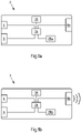
- Fig. 1 shows a conventional wired motor roller controller 2 for motor rollers.
- the controller 2 has a power inlet 4.
- the power inlet 4 preferably is a DC-power inlet 4, in particular 12V or 24V power inlet.
- Power inlet 4 receives the electric power for operating the controller 2.
- the Power inlet 4 may also receive the electric power for operation a motor roller.
- a motor roller can be connected to a motor roller port 6.
- Motor roller port 6 has at least two, preferably four connectors for connecting the motor roller. Via the motor roller port 6 the motor-roller may at least be supplied with electrical energy. In addition, the motor-roller may be controlled by exchanging control signals and/or status information signals via the motor roller port 6. Control of motor rollers as such is well known and will not be described in more detail.
- I/O-port 8a can be a communication port for wired communication, for instance according to an industry standard, in particular as mentioned above. Moreover, I/O-port 8a can support any proprietary protocol. Via port 8a control signals and/or status information can be exchanged between the controller 2 and a central control center.
- the I/O port is connected to a central controller (not shown) via a wired serial bus 10.
- the wired serial bus can be arranged according to any known industry standard, for instance as explained above.
- the wired serial bus 10 can be at least two wired, preferably at least four wired bus.
- the wired serial bus 10 can connect at least two consecutive controllers 2 serially.
- the wired serial bus 10 can be terminated at a controller 2.
- the wired serial bus 10 can connect the least two consecutive controllers 2 with a central controller.
- the wired serial bus 10 can be terminated at the central controller.
- the controller 2 further has a central processor 26 which is connected to the power inlet 4, the motor roller port 6 and the I/O-port 8a.
- the central processor 26 can be programmed.
- the programming may be understood as setting parameters for the motor roller. According to the programming the motor roller is instructed via motor roller port 6 to at least rotate in a certain direction at a certain speed. Any other parameters as described above can be parameterized and programmed.
- controller 2 may have a memory 30.
- central processor 26 outputs control signals for a motor roller via motor roller port 6.
- the signals output, the amperage as well as the voltage of the output signals and the like depend on configuration settings (parameters) of controller 2.
- central processor 26 reads out status information from the motor roller via motor roller port 6.
- a controller 3 for a merger/diverter may be set up similarly to the controller 2 and the description of the controller 2 may apply for a controller 3 for a merger/diverter.
- the merger/diverter controller 3 may have a transporter port 6a, via which control signals for a transport means on the merger/diverter may be controlled.
- the control of a merger/diverter is known in the art.
- controller 3 may also comprise a wireless unit 28b.
- the wireless unit 28b may be arranged to exchange signals with wireless unit 28a of other controllers 2.
- a conventional conveyor as illustrated in Fig. 2 may comprise motor rollers 14 and rollers 16.
- a conveyor line 12 may have two or more conveyor zones 12a. Within each conveyor zone 12a, one motor roller 14 is mechanically coupled with at least one, preferably between two to seven rollers 16, in particular by V-belts or poly-V-belts or the like. Other mechanical couplings are also possible.
- a motor roller 14 is rotatable arranged on a rack 18 and comprises a motor within a hollow tube.
- the motor within the hollow tube is connected to the controller 2 via its motor roller port 6.
- a separate controller 2 is provided controlling the respective motor-roller 14.
- the controllers 2 are connected to power and a control bus via their power inlets 4 and I/O-ports 8.
- the controllers 2 along the respective zones 12a are connected to each other and a central controller 30 via the serial bus 10. Control signals are exchanged between the controllers 2 and the central controller 30 using the serial bus 10.
- a conveyor sys 12 according to embodiments with a plurality of conveyor zones 12a-d and a merger/diverter 14 is illustrated in Fig. 3 .
- Fig. 3 illustrates a conveying system, where a first conveying zone 12a with a first controller 2a is arranged upstream of a merger/diverter 14. A second conveying zone 12b with a second controller 2b is arranged downstream merger/diverter 14.
- Conveying zones 12c, 12d are arranged for feeding products onto merger/diverter 14 or transporting products away from merger/diverter 14.
- the operation of conveying zones 12c, d in terms of a merge/divert operation using merger/diverter 14 is well known in the art and will not been described in detail.
- a first serial bus 10a connects controller 2a and any upstream controllers 2.
- a second serial bus 10b connects controller 2b with downstream controllers.
- first serial bus 10a upstream of merger/diverter 14 and a second serial bus 10b downstream of merger/diverter 14.
- second serial bus 10b downstream of merger/diverter 14.
- the same may apply for the conveying zones 12c, d.
- third serial bus 10c connecting controller 2c and within conveying zone 12d there is a fourth serial bus 10d connecting controller 2d.
- Serial busses 10a-d are all terminated at a central controller 30.
- serial busses 10a-d terminate at the respective controllers 2a-d spatially neighbouring merger/diverter 14. It should be noted that it is not necessary that all serial busses 10a-d are separated from each other. However, the gist of the invention lies in that at least two of the serial busses 10a-d are separate from each other.
- Controller 3 is a merger/diverter controller 3 as explained above.
- Merger/diverter controller 3 may control merger/diverter 14 and the respective transport operation thereon to merge/divert products onto the conveyor as explained above.
- Each of the controllers 2a-d, 3 may have a wireless unit 28a, 28b. Using wireless unit 28a, b, the controllers 2a-d, 3 may exchange control signals in order to enable a merge/divert operation on merger/diverter 14. These wireless signals may be signals for orchestrating controllers 2a-d, 3 during the merge/divert operation in order not to cause congestions or errors during the merge/divert operation. The wireless signals may be enhanced using also wired signals via the wired serial busses 10a-e and central controller 30.
Landscapes
- Engineering & Computer Science (AREA)
- Mechanical Engineering (AREA)
- Control Of Conveyors (AREA)
- Branching, Merging, And Special Transfer Between Conveyors (AREA)
Priority Applications (5)
| Application Number | Priority Date | Filing Date | Title |
|---|---|---|---|
| EP21184049.1A EP4116237A1 (de) | 2021-07-06 | 2021-07-06 | Fördersystem, motorwalzensteuergerät und verfahren zum betrieb eines fördersystems |
| CN202280047541.2A CN117597295A (zh) | 2021-07-06 | 2022-06-09 | 输送机系统、电机辊控制器和操作输送机系统的方法 |
| PCT/EP2022/065704 WO2023280506A1 (en) | 2021-07-06 | 2022-06-09 | Conveyor system, motor roller controller and method for operating a conveyor system |
| JP2024500489A JP2024525251A (ja) | 2021-07-06 | 2022-06-09 | コンベヤシステム、モータローラコントローラ、およびコンベヤシステムを動作させるための方法 |
| US18/401,895 US20240228182A9 (en) | 2021-07-06 | 2024-01-02 | Conveyor system, motor roller controller and method for operating a conveyor system |
Applications Claiming Priority (1)
| Application Number | Priority Date | Filing Date | Title |
|---|---|---|---|
| EP21184049.1A EP4116237A1 (de) | 2021-07-06 | 2021-07-06 | Fördersystem, motorwalzensteuergerät und verfahren zum betrieb eines fördersystems |
Publications (1)
| Publication Number | Publication Date |
|---|---|
| EP4116237A1 true EP4116237A1 (de) | 2023-01-11 |
Family
ID=76829356
Family Applications (1)
| Application Number | Title | Priority Date | Filing Date |
|---|---|---|---|
| EP21184049.1A Pending EP4116237A1 (de) | 2021-07-06 | 2021-07-06 | Fördersystem, motorwalzensteuergerät und verfahren zum betrieb eines fördersystems |
Country Status (5)
| Country | Link |
|---|---|
| US (1) | US20240228182A9 (de) |
| EP (1) | EP4116237A1 (de) |
| JP (1) | JP2024525251A (de) |
| CN (1) | CN117597295A (de) |
| WO (1) | WO2023280506A1 (de) |
Cited By (1)
| Publication number | Priority date | Publication date | Assignee | Title |
|---|---|---|---|---|
| USD1017945S1 (en) * | 2021-02-07 | 2024-03-12 | Guangzhou Trond Display Co., Ltd | Conveyor |
Families Citing this family (1)
| Publication number | Priority date | Publication date | Assignee | Title |
|---|---|---|---|---|
| WO2026002750A1 (en) * | 2024-06-26 | 2026-01-02 | Interroll Holding Ag | Conveyor arrangement with regerative power levelling |
Citations (5)
| Publication number | Priority date | Publication date | Assignee | Title |
|---|---|---|---|---|
| US8695786B2 (en) * | 2010-12-07 | 2014-04-15 | Interroll Holding Ag | Singulated release for zoned conveyor systems |
| US20140343720A1 (en) * | 2012-02-05 | 2014-11-20 | Matthews Resources, Inc. | Conveying systems and methods of associating data with an item transported by a conveying system |
| US9809388B2 (en) * | 2014-06-13 | 2017-11-07 | Bastian Solutions, Llc | Cross belt slat sorter |
| EP3100340B1 (de) | 2014-01-29 | 2018-04-18 | Dimitar Petrov | Spannungsversorgung und steuerschaltung für motorisierte trägerolle |
| US10341135B2 (en) * | 2015-12-30 | 2019-07-02 | Nova-Tron Controls Corp. | Zone control system for conveyor system |
Family Cites Families (5)
| Publication number | Priority date | Publication date | Assignee | Title |
|---|---|---|---|---|
| US5186308A (en) * | 1991-09-19 | 1993-02-16 | Munro Mark S | Electrical system for industrial conveyors |
| JP2000264426A (ja) * | 1999-03-18 | 2000-09-26 | Hirakawa Denki Kk | 搬送装置、及び該装置に使用される搬送ユニット |
| JP2004307219A (ja) * | 2004-07-26 | 2004-11-04 | Ito Denki Kk | コンベアシステムの制御装置並びに方法、及び、コンベアシステムのモニタリング装置 |
| JP6804979B2 (ja) * | 2014-11-18 | 2020-12-23 | 伊東電機株式会社 | コンベヤ装置、コンベヤシステム、ゾーンコントローラ及びコンベヤ装置の製造方法 |
| JP7149607B2 (ja) * | 2019-10-25 | 2022-10-07 | 伊東電機株式会社 | コンベヤシステム |
-
2021
- 2021-07-06 EP EP21184049.1A patent/EP4116237A1/de active Pending
-
2022
- 2022-06-09 WO PCT/EP2022/065704 patent/WO2023280506A1/en not_active Ceased
- 2022-06-09 CN CN202280047541.2A patent/CN117597295A/zh active Pending
- 2022-06-09 JP JP2024500489A patent/JP2024525251A/ja active Pending
-
2024
- 2024-01-02 US US18/401,895 patent/US20240228182A9/en active Pending
Patent Citations (5)
| Publication number | Priority date | Publication date | Assignee | Title |
|---|---|---|---|---|
| US8695786B2 (en) * | 2010-12-07 | 2014-04-15 | Interroll Holding Ag | Singulated release for zoned conveyor systems |
| US20140343720A1 (en) * | 2012-02-05 | 2014-11-20 | Matthews Resources, Inc. | Conveying systems and methods of associating data with an item transported by a conveying system |
| EP3100340B1 (de) | 2014-01-29 | 2018-04-18 | Dimitar Petrov | Spannungsversorgung und steuerschaltung für motorisierte trägerolle |
| US9809388B2 (en) * | 2014-06-13 | 2017-11-07 | Bastian Solutions, Llc | Cross belt slat sorter |
| US10341135B2 (en) * | 2015-12-30 | 2019-07-02 | Nova-Tron Controls Corp. | Zone control system for conveyor system |
Cited By (1)
| Publication number | Priority date | Publication date | Assignee | Title |
|---|---|---|---|---|
| USD1017945S1 (en) * | 2021-02-07 | 2024-03-12 | Guangzhou Trond Display Co., Ltd | Conveyor |
Also Published As
| Publication number | Publication date |
|---|---|
| CN117597295A (zh) | 2024-02-23 |
| JP2024525251A (ja) | 2024-07-11 |
| WO2023280506A1 (en) | 2023-01-12 |
| US20240228182A9 (en) | 2024-07-11 |
| US20240132298A1 (en) | 2024-04-25 |
Similar Documents
| Publication | Publication Date | Title |
|---|---|---|
| US20240132298A1 (en) | Conveyor system, motor roller controller and method for operating a conveyor system | |
| US7360638B2 (en) | Integrated control card for conveying systems | |
| US6532508B2 (en) | Control system for controlling safety-critical processes | |
| US7035714B2 (en) | Integrated conveyor bed | |
| KR102064294B1 (ko) | 택배화물 분류시스템 | |
| CN113260584B (zh) | 具有集成控制器的电机驱动输送机辊 | |
| WO2003002436A1 (en) | Zone controller | |
| CN113811499B (zh) | 一种模块化输送机系统及控制方法 | |
| WO2003000574A1 (fr) | Unite de commande de zone | |
| JP7411586B2 (ja) | データ読み出しを用いたアナログ制御移送デバイス | |
| JP7614620B2 (ja) | コンベヤ装置用コントローラ、並びに、コンベヤ装置 | |
| EP4080302B1 (de) | Fördersystem, motorwalzensteuergerät und verfahren zum betrieb eines fördersystems | |
| US8369982B2 (en) | Method and device for inserting, collecting or collating a plurality of flexible, planar products | |
| CN213504691U9 (zh) | 散料在线换向装置及应用该换向装置的散料在线输送系统 | |
| AU2023203279B2 (en) | Non-PLC-based conveyor controller | |
| US20230391556A1 (en) | Motor-driven conveyor-roller controller, system comprising such a controller and method for operating a motor roller | |
| EP4283419B1 (de) | Fördersystem, motor-rollen-steuerung und verfahren zum betreiben eines fördersystems | |
| EP4456488A1 (de) | Motorrollensteuerungsproxy | |
| JP2002284334A (ja) | コンベアの制御装置 | |
| JPH08258955A (ja) | 搬送方法 |
Legal Events
| Date | Code | Title | Description |
|---|---|---|---|
| PUAI | Public reference made under article 153(3) epc to a published international application that has entered the european phase |
Free format text: ORIGINAL CODE: 0009012 |
|
| STAA | Information on the status of an ep patent application or granted ep patent |
Free format text: STATUS: THE APPLICATION HAS BEEN PUBLISHED |
|
| AK | Designated contracting states |
Kind code of ref document: A1 Designated state(s): AL AT BE BG CH CY CZ DE DK EE ES FI FR GB GR HR HU IE IS IT LI LT LU LV MC MK MT NL NO PL PT RO RS SE SI SK SM TR |
|
| STAA | Information on the status of an ep patent application or granted ep patent |
Free format text: STATUS: REQUEST FOR EXAMINATION WAS MADE |
|
| 17P | Request for examination filed |
Effective date: 20230704 |
|
| RBV | Designated contracting states (corrected) |
Designated state(s): AL AT BE BG CH CY CZ DE DK EE ES FI FR GB GR HR HU IE IS IT LI LT LU LV MC MK MT NL NO PL PT RO RS SE SI SK SM TR |
|
| STAA | Information on the status of an ep patent application or granted ep patent |
Free format text: STATUS: EXAMINATION IS IN PROGRESS |
|
| 17Q | First examination report despatched |
Effective date: 20250703 |