EP4116706B1 - Automatischer analysator und verfahren zum installieren von trennsäulen in einem automatisierten analysator - Google Patents
Automatischer analysator und verfahren zum installieren von trennsäulen in einem automatisierten analysator Download PDFInfo
- Publication number
- EP4116706B1 EP4116706B1 EP21765217.1A EP21765217A EP4116706B1 EP 4116706 B1 EP4116706 B1 EP 4116706B1 EP 21765217 A EP21765217 A EP 21765217A EP 4116706 B1 EP4116706 B1 EP 4116706B1
- Authority
- EP
- European Patent Office
- Prior art keywords
- separation
- unit
- separation column
- installation
- columns
- Prior art date
- Legal status (The legal status is an assumption and is not a legal conclusion. Google has not performed a legal analysis and makes no representation as to the accuracy of the status listed.)
- Active
Links
Images




Classifications
-
- G—PHYSICS
- G01—MEASURING; TESTING
- G01N—INVESTIGATING OR ANALYSING MATERIALS BY DETERMINING THEIR CHEMICAL OR PHYSICAL PROPERTIES
- G01N30/00—Investigating or analysing materials by separation into components using adsorption, absorption or similar phenomena or using ion-exchange, e.g. chromatography or field flow fractionation
- G01N30/02—Column chromatography
- G01N30/88—Integrated analysis systems specially adapted therefor, not covered by a single one of the groups G01N30/04 - G01N30/86
-
- G—PHYSICS
- G01—MEASURING; TESTING
- G01N—INVESTIGATING OR ANALYSING MATERIALS BY DETERMINING THEIR CHEMICAL OR PHYSICAL PROPERTIES
- G01N30/00—Investigating or analysing materials by separation into components using adsorption, absorption or similar phenomena or using ion-exchange, e.g. chromatography or field flow fractionation
- G01N30/02—Column chromatography
- G01N30/26—Conditioning of the fluid carrier; Flow patterns
- G01N30/38—Flow patterns
- G01N30/46—Flow patterns using more than one column
-
- G—PHYSICS
- G01—MEASURING; TESTING
- G01N—INVESTIGATING OR ANALYSING MATERIALS BY DETERMINING THEIR CHEMICAL OR PHYSICAL PROPERTIES
- G01N30/00—Investigating or analysing materials by separation into components using adsorption, absorption or similar phenomena or using ion-exchange, e.g. chromatography or field flow fractionation
- G01N30/02—Column chromatography
- G01N30/86—Signal analysis
-
- G—PHYSICS
- G01—MEASURING; TESTING
- G01N—INVESTIGATING OR ANALYSING MATERIALS BY DETERMINING THEIR CHEMICAL OR PHYSICAL PROPERTIES
- G01N35/00—Automatic analysis not limited to methods or materials provided for in any single one of groups G01N1/00 - G01N33/00; Handling materials therefor
- G01N35/00584—Control arrangements for automatic analysers
- G01N35/00722—Communications; Identification
- G01N35/00732—Identification of carriers, materials or components in automatic analysers
-
- G—PHYSICS
- G01—MEASURING; TESTING
- G01N—INVESTIGATING OR ANALYSING MATERIALS BY DETERMINING THEIR CHEMICAL OR PHYSICAL PROPERTIES
- G01N30/00—Investigating or analysing materials by separation into components using adsorption, absorption or similar phenomena or using ion-exchange, e.g. chromatography or field flow fractionation
- G01N30/02—Column chromatography
- G01N30/88—Integrated analysis systems specially adapted therefor, not covered by a single one of the groups G01N30/04 - G01N30/86
- G01N2030/8804—Integrated analysis systems specially adapted therefor, not covered by a single one of the groups G01N30/04 - G01N30/86 automated systems
-
- G—PHYSICS
- G01—MEASURING; TESTING
- G01N—INVESTIGATING OR ANALYSING MATERIALS BY DETERMINING THEIR CHEMICAL OR PHYSICAL PROPERTIES
- G01N35/00—Automatic analysis not limited to methods or materials provided for in any single one of groups G01N1/00 - G01N33/00; Handling materials therefor
- G01N35/00584—Control arrangements for automatic analysers
- G01N35/00722—Communications; Identification
- G01N35/00732—Identification of carriers, materials or components in automatic analysers
- G01N2035/00742—Type of codes
- G01N2035/00752—Type of codes bar codes
-
- G—PHYSICS
- G01—MEASURING; TESTING
- G01N—INVESTIGATING OR ANALYSING MATERIALS BY DETERMINING THEIR CHEMICAL OR PHYSICAL PROPERTIES
- G01N35/00—Automatic analysis not limited to methods or materials provided for in any single one of groups G01N1/00 - G01N33/00; Handling materials therefor
- G01N35/00584—Control arrangements for automatic analysers
- G01N35/00722—Communications; Identification
- G01N35/00732—Identification of carriers, materials or components in automatic analysers
- G01N2035/00821—Identification of carriers, materials or components in automatic analysers nature of coded information
- G01N2035/00831—Identification of carriers, materials or components in automatic analysers nature of coded information identification of the sample, e.g. patient identity, place of sampling
-
- G—PHYSICS
- G01—MEASURING; TESTING
- G01N—INVESTIGATING OR ANALYSING MATERIALS BY DETERMINING THEIR CHEMICAL OR PHYSICAL PROPERTIES
- G01N35/00—Automatic analysis not limited to methods or materials provided for in any single one of groups G01N1/00 - G01N33/00; Handling materials therefor
- G01N35/00584—Control arrangements for automatic analysers
- G01N35/00722—Communications; Identification
- G01N35/00732—Identification of carriers, materials or components in automatic analysers
- G01N2035/00821—Identification of carriers, materials or components in automatic analysers nature of coded information
- G01N2035/00851—Identification of carriers, materials or components in automatic analysers nature of coded information process control parameters
-
- G—PHYSICS
- G01—MEASURING; TESTING
- G01N—INVESTIGATING OR ANALYSING MATERIALS BY DETERMINING THEIR CHEMICAL OR PHYSICAL PROPERTIES
- G01N35/00—Automatic analysis not limited to methods or materials provided for in any single one of groups G01N1/00 - G01N33/00; Handling materials therefor
- G01N35/00584—Control arrangements for automatic analysers
- G01N35/00722—Communications; Identification
- G01N2035/00891—Displaying information to the operator
- G01N2035/009—Displaying information to the operator alarms, e.g. audible
Definitions
- the present invention relates to an automatic analyzer for analyzing contents of a biological sample and a method of separation column installation in the automatic analyzer, and more particularly, to an automatic analyzer in which plural columns can be installed in parallel in a separation unit thereof and a method of separation column installation therein.
- the automatic analyzer for analyzing a biological sample such as blood and urine is disclosed in Patent Literature 1.
- the automatic analyzer is, for purposes of operation efficiency improvement, human error elimination, and analysis efficiency enhancement, configured as follows.
- the automatic analyzer includes an operation unit for managing, in an integrated manner, one or more analysis units to carry out analysis, and the operation unit is provided with a means, for example, a barcode reader or an RFID reader, for reading identification information for identifying samples and reagents.
- the automatic analyzer has a function to read, using the means, identification information affixed on sample or reagent containers, automatically search examination information stored in an examination information storage means provided in the operation unit for referable examination information and display a search result on a screen included in the operation unit, a function to transition, when the user selects target examination information on the search result display screen, to a screen displaying details of the examination information, and a function to return from the details screen to the examination result screen.
- JP H09 171022 A discloses an apparatus for recognition of exchangeable parts in an analytical measuring instrument or in an analytical measurement system with several analytical devices, which contain exchangeable parts, comprising identification modules each attached to an exchangeable part, and transmit-receive devices which can receive information signals from an identification module and send information signals to an identification module, and a control device which evaluates the information from an identification module.
- Patent literature 1 International Publication 2011/067888
- an analysis object is isolated or plural analysis objects are mutually separated using a separation column containing a filler called a stationary phase.
- a sample is injected into a liquid flow called a mobile phase and moves in a stationary phase (filler) in a separation column. While the sample moves in the stationary phase, differences between materials contained in the sample in terms of the intensities of their reactions against the stationary phase cause analysis objects to be separated.
- the separation column is an expendable item, and when it is repeatedly used involving filler contamination and deterioration, it comes to require replacement. Also, it is necessary to use various types of columns as required depending on object samples, analysis objects, and separation methods.
- separation columns are manually replaced by users, but human errors may cause wrong types of columns to be installed, or, even when correct types of columns are selected, may cause the selected columns to be installed in wrong positions.
- Patent Literature 1 A technique which can be used as a means for inhibiting human errors concerning installation in an automatic analyzer is described in Patent Literature 1.
- identification information given by, for example, RFID tags or barcodes affixed on reagent containers are mechanically read and the identification information read is managed being associated with positions in a refrigerator included in the analyzer.
- a main purpose is to make recognizable by the analyzer what reagents are placed in which positions in the refrigerator included in the analyzer, and, basically, which reagent containers are installed in which positions does not matter. This is because when reagent amended dispensing is necessary, where the reagent container is installed may be searched for based on the stored identification information, then, after position alignment, the reagent may be sucked in and dispensed.
- the present invention has been made in view of the above problem and provides an automatic analyzer for making chromatographic analysis selectively using plural types of separation columns wherein intended types of separation columns can be installed in aimed positions and a method of separation column installation in the automatic analyzer.
- the present invention includes plural means for solving the above problem, as defined in the appended claims.
- An automatic analyzer includes: an identification unit that reads, when the separation columns are installed in installation positions, identifiers the separation columns are provided with; a determination unit that determines whether or not identification information read, in the identification unit, from the identifiers matches an installation pattern registered beforehand; a notification unit that notifies an alarm when the identification information is determined, in the determination unit, not to match the installation pattern; a type setting unit that registers, as the installation pattern, separation column types respectively installable in the flow passages, and a maximum number setting unit that registers a maximum number of same-type separation columns installable in the flow passages.
- the present embodiment of the automatic analyzer will be described taking as an example a multi-item automatic analyzer (hereinafter referred to simply as an "automatic analyzer” or an “analyzer”) which can preprocess a biological sample such as blood or urine (hereinafter referred to simply as a “sample”) using a reagent and magnetic beads, separate substances of the sample by liquid chromatography, and analyze the masses of ionized substances.
- an automatic analyzer a multi-item automatic analyzer
- an automatic analyzer a multi-item automatic analyzer
- an automatic analyzer which can preprocess a biological sample such as blood or urine (hereinafter referred to simply as a “sa “sample") using a reagent and magnetic beads, separate substances of the sample by liquid chromatography, and analyze the masses of ionized substances.
- the form of the automatic analyzer is not limited to this.
- Fig. 1 is a drawing schematically illustrating a basic configuration of the automatic analyzer according to the present embodiment.
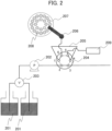
- Fig. 2 is a schematic diagram illustrating a configuration of a sample introduction unit illustrated in Fig. 1 .
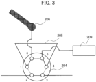
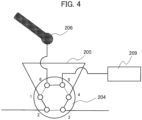
- Fig. 3 and Fig. 4 are schematic diagrams related to the position of the injection valve illustrated in Fig. 2 .
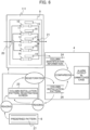
- Fig. 5 is a schematic diagram illustrating an exemplary separation column and an exemplary separation column identifier.
- the automatic analyzer 100 includes an analysis unit 101 configured mainly with a preprocessing unit 110, a separation unit 111 and a detection unit 112 and a control unit 102 configured mainly with an interface 1, a display unit 2, an input unit 3, a computer 4, an external storage unit 5, a memory 6 and a printer 7.
- the preprocessing unit 110 introduces a sample dispensed from a source specimen into the separation unit 111 after removing from the sample, using a reagent, magnetic beads (hydrophobic interactions) and an extraction solvent, unnecessary substances not to be analyzed.
- the separation unit 111 includes a sample introduction unit 8 to introduce the sample refined in the preprocessing unit 110 into separation columns 10, 11, 12, 13, 14 and a separation column oven 9 in which the separation columns 10, 11, 12, 13, 14 to separate an object of analysis can be installed in parallel.
- the sample introduction unit 8 includes a solvent sending pump 202 to feed a sample introduction solvent 201, a solvent switch valve 203 to control the composition of the sample introduction solvent 201, an injection valve 204, a sample loop 205, a sipper 206, and a syringe 209 which sucks the solution refined in the preprocessing unit 110 from a reaction vessel 208 held by a reaction solution disk 207 and introduces the sample into the sample loop 205.
- the injection valve 204 is a hexagonal valve which can, by switching flow passages, form two flow passage patterns. In position 1 shown in Fig. 3 , flow passages connecting ports 1 and 6, ports 2 and 3, and ports 4 and 5 are formed. In position 2 shown in Fig. 4 , flow passages connecting ports 1 and 2, ports 2 and 3, and ports 4 and 5 are formed.
- the injection valve 204 When the sample is sucked, the injection valve 204 is controlled to be in position 1 shown in Fig. 3 , and the sipper 206, the sample loop 205 and the syringe 209 are connected. At the same time, the sample introduction solvent 201, the solvent switch valve 203, the solvent sending pump 202, and a first separation column selector valve 20 are connected.
- the sipper 206 descends and sucks the sample from the reaction vessel 208 held by the reaction solution disk 207 to fill the sample loop 205 with the sample to, thereby, complete the preparation for flowing a mobile phase into the separation columns 10, 11, 12, 13, 14.
- the sample suction speed of the syringe 209 can be set, under control of the computer 4, to an optimum value for each analysis object.
- the injection valve 204 When introducing the sample into the separation columns 10, 11, 12, 13, 14, the injection valve 204 is controlled to be in position 2 shown in Fig. 4 , and the sample introduction solvent 201, solvent switch valve 203, solvent sending pump 202, sample loop 205, and first separation column selector valve 20 are connected. This makes it possible to introduce the sample, along the flow of the mobile phase, into the separation columns 10, 11, 12, 13, 14.
- the separation column oven 9 holds, in the flow passage therein, the separation columns 10, 11, 12, 13, 14 for separating an analysis object from foreign substances in parallel and is configured to adjust the temperature of the separation columns 10, 11, 12, 13, 14.
- the separation column oven 9 is externally provided with the first separation column selector valve 20 and a second separation column selector valve 21 for optionally connecting any of the separation columns 10, 11, 12, 13, 14 to the flow passage.
- a specific one of the separation columns 10, 11, 12, 13, 14 to be connected with the first separation column selector valve 20 and second separation column selector valve 21 is selected under control of the computer 4 included in the control unit 102.
- identification mechanisms 15, 16, 17, 18, 19 corresponding to the separation columns 10, 11, 12, 13, 14 are respectively disposed near the separation columns. As being described later, when the separation columns 10, 11, 12, 13, 14 are installed in their respective positions, the identification mechanisms 15, 16, 17, 18, 19 respectively read information given by identifiers 401 affixed to the separation columns.
- an identifier 401 is affixed to the side surface of each of the separation columns 10, 11, 12, 13, 14.
- the identifier 401 provides a separation column identification number for identifying a separation column type.
- the identifiers 401 read by the identification mechanisms 15, 16, 17, 18, 19 when the separation columns 10, 11, 12, 13, 14 are installed in their respective positions are inputted to the computer 4 via the interface 1.
- the separation column identification numbers are associated with the separation column installation positions in the separation column oven 9 and are stored in the memory 6 or in an appropriate memory area of the computer 4.
- the identifiers 401 may be optically readable ones, for example, barcodes (regardless of whether one dimensional or two dimensional) or ones to be read using radio waves (IC tags, radio tags), but they are not limited to these types and may be of any other type as far as information given by them can be read.
- the identification mechanisms 15, 16, 17, 18, 19 determine what types of separation columns 10, 11, 12, 13, 14 are installed in which positions.
- the identifiers 401 are barcodes
- barcode readers to emit laser beams to the barcodes and detect reflected light are used.
- RFID readers are used.
- the identification mechanisms may also be of any type of configuration as far as they can read information given by the identifiers 401.
- the identification mechanisms 15, 16, 17, 18, 19 make it possible to appropriately execute an identification step in which, when the separation columns 10, 11, 12, 13, 14 are installed in installation positions, the identifiers 401 affixed to the separation columns 10, 11, 12, 13, 14 are read.
- the detection unit 112 ionizes the sample separated in the separation unit 111 to let the ionized sample fly in vacuum.
- the analysis object is separated from the flying ions according to the mass-to-charge ratio (m/z) and is detected by the detector 22.
- m/z mass-to-charge ratio
- relative intensity variations of the analysis object can be detected at intervals in the form of detection peaks (mass spectrum).
- the mass spectrum based on the analysis object obtained by the detector 22 is subjected to analog-to-digital signal conversion by the A/D converter 23 to be then inputted to the computer 4 via the interface 1.
- the digital signals are converted, by quantitative value calculation processing based on detection peak area values, to density values of the analysis object component of the sample.
- the data having undergone conversion to represent densities is outputted via the interface 1; for example, printed out by an output device such as the printer 7, displayed on the screen of the display unit 2, or stored in the memory 6 or in the external storage unit 5.
- the display unit 2 in the control unit 102 is a device for displaying various information based on directions for display from the computer 4 and is configured including an input screen for various parameters and settings and a liquid crystal display for displaying information such as analysis data and measurement results obtained in an initial examination or in a re-examination.
- the display unit 2 may be a display device of a touch panel type for use also as the input unit 3 being described later.
- the input unit 3 is a mechanism for inputting direction signals to the computer 4 via the interface 1 and is configured including a keyboard and a mouse which are used to input various data representing, for example, various parameters and settings, analysis requests, and analysis start directions.
- the computer 4 is a device for making various arithmetic processing and controls operations of various devices included in the automatic analyzer 100 based on computer programs stored in the memory 6 being described later.
- the computer 4 of the present embodiment executes a determination step in which whether or not the identification information read from the identifiers 401 by the identification mechanisms 15, 16, 17, 18, 19 matches the pre-registered installation pattern is determined and a notification step in which, when the identification information is determined not to match the installation pattern, an alarm is notified.
- the computer 4 also controls the display of various setting screens such as the separation column installation pattern registration screen 25 and the separation column maximum installation number registration screen 28. These will be described in detail later.
- the external storage unit 5 is a recording medium arbitrarily removable from the interface 1, for example, an external USB memory.
- the information stored in the external storage unit 5 includes, for example, analysis item codes and parameters used for the analysis items.
- the parameters used for the analysis items include a preprocessing method, a separation method, and a detection method. Such information is stored in the memory 6 or in an appropriate memory area in the computer 4.
- the memory 6 stores, in addition to the information read from the external storage unit 5, operating conditions for various mechanisms of the automatic analyzer 100, analysis parameters for each analysis item, determination logic for reagent management, and analysis results.
- the memory 6 is a recording device, for example, a semiconductor memory like a flash memory or a magnetic disk as included in an HDD (Hard Disk Drive).
- Various parameters and setting values for controlling operations of devices included in the automatic analyzer 100 and various computer programs for executing various display processing are also recorded in the memory 6.
- Fig. 6 is a drawing schematically illustrating how comparison is made between separation column identification information and a separation column installation pattern.
- Fig. 7 is a drawing indicating examples of predefined patterns in a case where up to three same-type separation columns are installable in five flow passages.
- Fig. 8 and Fig. 9 are drawings showing display screen examples displayed when registering a separation column installation pattern selected from the predefined patterns shown in Fig. 6 .
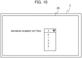
- Fig. 10 is a drawing showing a screen display example appearing when selecting a predefined pattern shown in Fig. 6 and registering a maximum number of same-type separation columns installable.
- the identification mechanisms 15, 16, 17, 18, 19 read the identifiers 401 respectively affixed to the separation columns 10, 11, 12, 13, 14.
- the computer 4 in the control unit 102 compares the separation column identification information 24 stored, being associated with the installation positions (flow passages) in the separation column oven 9, with the separation column installation pattern 26 pre-registered on the separation column installation pattern registration screen 25 and determines whether or not the comparison result is a match.
- the user registers, before installing the separation columns 10, 11, 12, 13, 14, a separation column installation pattern 26 like the ones shown in Fig. 7 on the separation column installation pattern registration screen 25 displayed, as shown in Fig. 8 and Fig. 9 , in the display unit 2.
- the input operation for registration is desirably made in the input unit 3 or in the display unit 2 of a touch-panel type.
- a pattern appropriate for the tendency of analysis made in the laboratory can be selected from the predefined patterns 27.
- the predefined patterns 27 may be, for example, "SETTING 1", “SETTING 2", “SETTING 3", - - -, as indicated in Fig. 7 .
- TYPE indicates that a specific type of separation column can be installed.
- ANY indicates that any type of separation column different from the specific type can be installed.
- a predefined pattern 27 is selected and is then registered as a separation column installation pattern 26 is illustrated in Fig. 8 and Fig. 9 .
- a separation column type is selectable using a pull-down menu.
- the selection method is not limited to a pull-down menu, and various selection methods can be used.
- the separation column installation pattern registration screen 25 is controlled as follows.
- the flow passages 2 and 3 are required to use the same type of separation column as used by the flow passage 1, so that the flow passages 1, 4, and 5 are displayed to allow editing, whereas the flow passages 2 and 3 are made uneditable.
- a separation column type is set for the flow passage 1
- the same separation column type is automatically set for the flow passages 2 and 3.
- the separation columns for the five flow passages in the separation unit 111 can include up to three same-type separation columns whereas, at the time of editing for the flow passage 1, a specific separation column type (e.g. "TYPE4" or "TYPE5") is already set for the flow passage 4 or 5, setting the specific separation column type also for the flow passage 1 causes the same-type separation columns to total four exceeding three set as the maximum number of same-type separation columns. Hence, as shown in Fig. 9 , the pull-down list for the flow passage 1 is controlled not to show the specific separation column type ("TYPE4" or "TYPES").
- the flow passage 2 and the flow passage 4 are required to use the same types of separation columns as for the flow passage 1 and the flow passage 3, respectively. Therefore, the separation column type is optional only for the flow passages 1, 3, and 5. Furthermore, in the case of "SETTING 3" and “SETTING 4" in Fig. 7 , a separation column type is already set for each flow passage, so that no other separation column type can be selected.
- the separation column maximum installation number registration screen 28 shown in Fig. 10 is used, when the user defines an installation pattern for the separation columns 10, 11, 12, 13, 14 installable in the flow passages in the separation unit 111, to register a maximum number of same-type separation columns which can be included in the separation columns 10, 11, 12, 13, 14 being installed.
- the screen is displayed in the display unit 2.
- the separation column installation patterns 26 registered on the separation column installation pattern registration screen 25 and the maximum installable number of same-type separation columns registered on the separation column maximum installation number registration screen 28 are inputted to the computer 4 via the interface 1 and are stored in an appropriate memory area.
- the identification mechanisms 15, 16, 17, 18, 19 read the identifiers 401 affixed to the separation columns 10, 11, 12, 13, 14 installed in the respective installation positions.
- the identification information read is inputted to the computer 4 in the control unit 102 via the interface 1 and is then associated, in the computer 4, with the flow passages 1 to 5 in the separation column oven to, thereby, generate the separation column identification information 24.
- This step is equivalent to the identification step in which, when the identification columns 10, 11, 12, 13, 14 are installed in the installation positions, the identifiers 401 provided on the separation columns 10, 11, 12, 13, 14 are read.
- the separation column identification information 24 is compared with the predefined separation column installation pattern 26, and, when the comparison result is a non-match, an alarm is outputted to the display unit 2 in the control unit 102.
- This step is equivalent to the determination step in which whether or not the identification information read from the identifiers 401 in the identification step matches the pre-registered installation pattern and to the notification step in which, when the determination result is a non-match, an alarm is notified.
- the alarm may be in the form of an error display on the screen in the display unit 2 or a sound output, but it may be in any other form as far as it notifies that wrong types of separation columns are installed in wrong positions.
- the computer 4 in the control unit 102 can mask, out of the separation columns 10, 11, 12, 13, 14, ones in non-matching positions to put them out of use for analysis.
- the analysis is desirably carried out using, out of the separation columns 10, 11, 12, 13, 14, only the ones in matching positions.
- the comparison between the separation column identification information 24 and the separation column installation pattern 26 is desirably carried out at the timing when the cover of the separation column oven 9 is closed. This allows the user to be alarmed before prime processing is executed after the cover of the separation column oven 9 is closed and prevents the prime processing from being executed.
- the timing of the comparison or alarming is not limited to when the cover of the separation column oven 9 is closed. It may also be when the separation columns 10, 11, 12, 13, 14 are installed in any positions.
- the above embodiment has been described based on a format in which the user registers a separation column installation pattern 26 selected from the predefined patterns 27, but the format is not a limited one, and the one as described below may also be used.
- a mode may be employed which, in such a case, makes it possible to, when the identification information on the separation columns 10, 11, 12, 13, 14 is read, register the current state of separation column installations as an initial separation column installation pattern 26. It is desirable that this mode becomes effective, for example, only at the time of analyzer setting up or when the analyzer is operated by a service person.
- the automatic analyzer 100 of the present embodiment described above is provided with the identification mechanisms 15, 16, 17, 18, 19 that read, when the separation columns 10, 11, 12, 13, 14 are installed in installation positions, the identifiers 401 provided on the separation columns 10, 11, 12, 13, 14, the computer 4 that determines whether or not the identification information read by the identification mechanisms 15, 16, 17, 18, 19 from the identifiers 401 matches the pre-registered installation pattern, and the display unit 2 that notifies an alarm when the computer 4 determines that the identification information does not match the installation pattern.
- the above configuration makes it possible, in the automatic analyzer 100 to carry out chromatographic analysis using plural, particularly, plural types of separation columns, to detect, out of the separation columns 10, 11, 12, 13, 14, ones installed in wrong positions before the separation columns are put in use.
- the separation column type is identified based on the information, and the composition of the solvent corresponding to the separation column type is determined by searching a table of solvent compositions predefined for various separation column types, problems such as detection accuracy deterioration and separation column breakage caused when a wrong separation column is used or when a wrong solvent composition is set do not occur.
- the separation columns are used being connected to flow passages, and when, at the time of changing the separation columns, the separation column types and the composition of the solvent used as a mobile phase largely change, it becomes necessary, in order to avoid a carry-over in the flow passages, to carry out equilibration for a long period of time and replace the solvent. Therefore, frequently changing the separation column types and installation positions causes a throughput reduction.
- the separation column installation pattern registration screen 25 for registering, as installation patterns, the types of the separation columns 10, 11, 12, 13, 14 installable in the respective flow passages further provided the user can select, out of the predefined installation patterns, one corresponding to the tendency of analysis made in the laboratory, so that the user is allowed to freely carry out analysis according to the operating conditions involved. This also makes it possible to reduce human errors.
- the separation column maximum installation number registration screen 28 for registering a maximum number of same-type separation columns installable in the flow passages among the separation columns 10, 11, 12, 13, 14 further provided, also, the user can select, out of the predefined installation patterns, one corresponding to the tendency of analysis made in the laboratory, so that the user is allowed to freely carry out analysis according to the operating conditions involved.
- the analyzer has a mode in which, when the identification information does not match the preset installation pattern, the current installation pattern of the separation columns 10, 11, 12, 13, 14 can be registered as a new installation pattern. This generates effects to save setting trouble for the user and allow the analyzer to be automatically set up and started up as intended by the user without being restricted by the predefined patterns 27.
- the present invention is not limited to the above embodiment, and can be modified in various ways and applied in various manners.
- the above embodiment has been described in details to make the invention easy to understand, and the invention is not limited to the analyzer including all the configurations described.
Landscapes
- Physics & Mathematics (AREA)
- Health & Medical Sciences (AREA)
- Life Sciences & Earth Sciences (AREA)
- Chemical & Material Sciences (AREA)
- Analytical Chemistry (AREA)
- Biochemistry (AREA)
- General Health & Medical Sciences (AREA)
- General Physics & Mathematics (AREA)
- Immunology (AREA)
- Pathology (AREA)
- Automatic Analysis And Handling Materials Therefor (AREA)
Claims (5)
- Automatische Analysevorrichtung, die eine Vorverarbeitungseinheit (110), eine Trenneinheit (111), eine Detektionseinheit (112) und eine Steuereinheit (102) enthält, wobei die Trenneinheit es ermöglicht, dass mehrere Trennsäulen (10, 11, 12, 13, 14) in darin vorgesehenen Strömungspassagen installiert werden können, wobei die automatische Analysevorrichtung umfasst:eine Identifikationseinheit (15, 16, 17, 18, 19), die, wenn die Trennsäulen an Installationspositionen installiert sind, dazu eingerichtet ist, Kennungen (401) zu lesen, mit denen die Trennsäulen versehen sind;eine Bestimmungseinheit (4), die dazu eingerichtet ist, zu bestimmen, ob in der Identifikationseinheit aus den Kennungen ausgelesene Identifikationsinformationen mit einem zuvor registrierten Installationsmuster übereinstimmen oder nicht;eine Meldeeinheit (2), die dazu eingerichtet ist, einen Alarm zu melden, wenn in der Bestimmungseinheit bestimmt wird, dass die Identifikationsinformationen nicht mit dem Installationsmuster übereinstimmen;eine Typeneinstelleinheit (25), die als das Installationsmuster Trennsäulentypen registriert, die jeweils in den Strömungskanälen installiert werden können, undeine Maximalanzahl-Einstelleinheit (28), die dazu eingerichtet ist, eine maximale Anzahl von Trennsäulen des gleichen Typs, die in den Strömungskanälen installiert werden können, zu registrieren.
- Automatische Analysevorrichtung nach Anspruch 1,
wobei, wenn die maximale Installationsanzahl eingestellt ist und die Installation der maximalen Installationsanzahl spezifischer Trennsäulen, deren maximale Installationsanzahl eingestellt ist, registriert ist, die Steuereinheit (102) dazu eingerichtet ist, nur die Registrierung der Trennsäule eines anderen Typs als die spezifische Trennsäule zu erlauben, wenn der Benutzer den Typ der Trennsäule an einer anderen Position durch die Typeneinstelleinheit auswählt. - Automatische Analysevorrichtung nach Anspruch 1,
wobei die automatische Analysevorrichtung einen Modus aufweist, in dem ein aktuelles Installationsmuster der Trennsäule als ein neues Installationsmuster registriert werden kann, wenn sich die Identifikationsinformation von dem vorläufig eingestellten Installationsmuster unterscheiden. - Automatische Analysevorrichtung nach Anspruch 1,
wobei die Steuereinheit dazu eingerichtet ist, die Trennsäule an einem nicht übereinstimmenden Teil zu maskieren und eine Analyse nur mit der Trennsäule an einem übereinstimmenden Teil durchzuführen, wenn die Bestimmungseinheit bestimmt, dass die Identifikationsinformationen nicht mit dem Installationsmuster übereinstimmen. - Verfahren zur Installation von Trennsäulen für eine automatische Analysevorrichtung nach Anspruch 1, wobei das Verfahren umfasst:einen Identifikationsschritt zum Lesen, unter Verwendung der Identifikationseinheit (15, 16, 17, 18, 19) von Kennungen, mit denen die Trennsäulen versehen sind, wenn die Trennsäulen an Installationspositionen installiert sind;einen Bestimmungsschritt zum Bestimmen, unter Verwendung der Bestimmungseinheit (4), ob die im Identifikationsschritt aus den Kennungen gelesenen Identifikationsinformationen mit einem zuvor registrierten Installationsmuster übereinstimmen oder nicht;einen Meldeschritt zum Melden eines Alarms, unter Verwendung der Meldeeinheit (2), wenn im Bestimmungsschritt festgestellt wird, dass die Identifikationsinformationen nicht mit dem Installationsmuster übereinstimmen;einen Typeneinstellschritt zum Registrieren, unter Verwendung der Typeneinstelleinheit (25), von Trennsäulentypen, die jeweils in den Strömungskanälen installiert werden können, als das Installationsmuster; undeinen Schritt zum Registrieren, unter Verwendung der Maximalanzahl-Einstelleinheit, einer maximalen Anzahl von Trennsäulen gleichen Typs, die in den Strömungskanälen installiert werden können.
Applications Claiming Priority (2)
| Application Number | Priority Date | Filing Date | Title |
|---|---|---|---|
| JP2020036373 | 2020-03-04 | ||
| PCT/JP2021/002566 WO2021176885A1 (ja) | 2020-03-04 | 2021-01-26 | 自動分析装置および自動分析装置での分離カラムの設置方法 |
Publications (3)
| Publication Number | Publication Date |
|---|---|
| EP4116706A1 EP4116706A1 (de) | 2023-01-11 |
| EP4116706A4 EP4116706A4 (de) | 2024-04-10 |
| EP4116706B1 true EP4116706B1 (de) | 2024-11-13 |
Family
ID=77613657
Family Applications (1)
| Application Number | Title | Priority Date | Filing Date |
|---|---|---|---|
| EP21765217.1A Active EP4116706B1 (de) | 2020-03-04 | 2021-01-26 | Automatischer analysator und verfahren zum installieren von trennsäulen in einem automatisierten analysator |
Country Status (5)
| Country | Link |
|---|---|
| US (1) | US20230098770A1 (de) |
| EP (1) | EP4116706B1 (de) |
| JP (1) | JP7318106B2 (de) |
| CN (1) | CN115210565B (de) |
| WO (1) | WO2021176885A1 (de) |
Family Cites Families (14)
| Publication number | Priority date | Publication date | Assignee | Title |
|---|---|---|---|---|
| US4975647A (en) * | 1987-06-01 | 1990-12-04 | Nova Biomedical Corporation | Controlling machine operation with respect to consumable accessory units |
| DE19540527A1 (de) * | 1995-10-31 | 1997-05-07 | Hewlett Packard Gmbh | Vorrichtung zur Erkennung austauschbarer Teile in analytischen Meßgeräten |
| JP2004085357A (ja) * | 2002-08-27 | 2004-03-18 | Shimadzu Corp | クロマトグラフ装置用データ管理装置 |
| JP2008107136A (ja) * | 2006-10-24 | 2008-05-08 | Hitachi High-Technologies Corp | 分析システムおよびその制御方法 |
| WO2010068276A1 (en) * | 2008-12-10 | 2010-06-17 | Alltech Associates Inc. | Chromatography systems and system components |
| JP2011099679A (ja) * | 2009-11-04 | 2011-05-19 | Hitachi High-Technologies Corp | 分析システムおよびその制御方法 |
| JP5753792B2 (ja) | 2009-12-03 | 2015-07-22 | 株式会社日立ハイテクノロジーズ | 自動分析装置 |
| US9304518B2 (en) * | 2011-08-24 | 2016-04-05 | Bio-Rad Laboratories, Inc. | Modular automated chromatography system |
| WO2015063886A1 (ja) * | 2013-10-30 | 2015-05-07 | 株式会社島津製作所 | 液体クロマトグラフ装置 |
| US20170010243A1 (en) * | 2014-02-11 | 2017-01-12 | Büchi Labortechnik AG | Multiple column chromatographic system and methods of use |
| CN106461624B (zh) * | 2014-03-04 | 2019-01-11 | 托夫沃克股份公司 | 用于确定层析图谱的方法和设备 |
| CN104897817B (zh) * | 2015-06-18 | 2017-03-01 | 常州三泰科技有限公司 | 色谱仪以及重复使用色谱柱的方法 |
| JP6881473B2 (ja) * | 2017-01-10 | 2021-06-02 | 株式会社島津製作所 | クロマトグラフ装置用制御装置 |
| WO2019023641A1 (en) * | 2017-07-27 | 2019-01-31 | CEM Corporation, Lucidity Division | GAS CHROMATOGRAPHIC DEVICE WITH COLUMN RECOGNITION TECHNOLOGY SYSTEM AND METHOD OF USING THE SAME |
-
2021
- 2021-01-26 US US17/908,112 patent/US20230098770A1/en active Pending
- 2021-01-26 CN CN202180016882.9A patent/CN115210565B/zh active Active
- 2021-01-26 JP JP2022505026A patent/JP7318106B2/ja active Active
- 2021-01-26 EP EP21765217.1A patent/EP4116706B1/de active Active
- 2021-01-26 WO PCT/JP2021/002566 patent/WO2021176885A1/ja not_active Ceased
Also Published As
| Publication number | Publication date |
|---|---|
| CN115210565A (zh) | 2022-10-18 |
| EP4116706A4 (de) | 2024-04-10 |
| WO2021176885A1 (ja) | 2021-09-10 |
| JP7318106B2 (ja) | 2023-07-31 |
| JPWO2021176885A1 (de) | 2021-09-10 |
| CN115210565B (zh) | 2024-06-18 |
| EP4116706A1 (de) | 2023-01-11 |
| US20230098770A1 (en) | 2023-03-30 |
Similar Documents
| Publication | Publication Date | Title |
|---|---|---|
| US4873633A (en) | User controlled off-center light absorbance reading adjuster in a liquid handling and reaction system | |
| JP7317915B2 (ja) | 自動分析装置 | |
| EP3786634B1 (de) | Techniken zur überprüfung des zustands von analysatoren | |
| EP3425369A1 (de) | System und verfahren zur automatisierten klinischen diagnose | |
| EP3779461B1 (de) | Automatisierte analysevorrichtung | |
| EP3839499A1 (de) | Techniken zur überwachung eines analysators mit mehreren flüssigkeitschromatographieströmen | |
| KR20130107202A (ko) | 진단 기기 및 유동 공정 | |
| US20200333367A1 (en) | Analysis method of automatic analyser | |
| JP2010256051A (ja) | 自動分析装置 | |
| CN109387648A (zh) | 自动分析系统 | |
| EP1668344A2 (de) | Verfahren zur identifizierung von in einem klinischen analyseautomaten zu verwendenden objekten | |
| JP2018080957A (ja) | 自動分析装置及びプログラム | |
| EP3901632B1 (de) | Vorrichtung zur automatisierten analyse und analyseverfahren | |
| EP4116706A1 (de) | Automatischer analysator und verfahren zum installieren von trennsäulen in einem automatisierten analysator | |
| JP2009204446A (ja) | 自動分析装置 | |
| JP7329625B2 (ja) | 自動分析装置、自動分析装置の表示システム、および自動分析装置における表示方法 | |
| JP7174066B2 (ja) | 自動分析装置 | |
| EP4492065A1 (de) | Automatische analysevorrichtung | |
| EP3629030B1 (de) | Anzeigeverfahren, probenanalysator und aufzeichnungsmedium | |
| CN116745624A (zh) | 自动分析装置及自动分析装置的控制方法 | |
| JP4642954B2 (ja) | 自動分析装置 | |
| JP4838855B2 (ja) | 分析装置 | |
| EP3715833B1 (de) | Fluoreszenzbildanalysator und fluoreszenzbildanalyseverfahren | |
| JP7570497B2 (ja) | 分析システム及び分析システム用プログラム | |
| EP4545973A1 (de) | Automatische analysevorrichtung und verfahren zum lesen von informationen auf einer automatischen analysevorrichtung |
Legal Events
| Date | Code | Title | Description |
|---|---|---|---|
| STAA | Information on the status of an ep patent application or granted ep patent |
Free format text: STATUS: THE INTERNATIONAL PUBLICATION HAS BEEN MADE |
|
| PUAI | Public reference made under article 153(3) epc to a published international application that has entered the european phase |
Free format text: ORIGINAL CODE: 0009012 |
|
| STAA | Information on the status of an ep patent application or granted ep patent |
Free format text: STATUS: REQUEST FOR EXAMINATION WAS MADE |
|
| 17P | Request for examination filed |
Effective date: 20220829 |
|
| AK | Designated contracting states |
Kind code of ref document: A1 Designated state(s): AL AT BE BG CH CY CZ DE DK EE ES FI FR GB GR HR HU IE IS IT LI LT LU LV MC MK MT NL NO PL PT RO RS SE SI SK SM TR |
|
| DAV | Request for validation of the european patent (deleted) | ||
| DAX | Request for extension of the european patent (deleted) | ||
| A4 | Supplementary search report drawn up and despatched |
Effective date: 20240311 |
|
| RIC1 | Information provided on ipc code assigned before grant |
Ipc: G01N 30/88 20060101ALI20240304BHEP Ipc: G01N 30/86 20060101ALI20240304BHEP Ipc: G01N 30/46 20060101ALI20240304BHEP Ipc: G01N 30/02 20060101AFI20240304BHEP |
|
| GRAP | Despatch of communication of intention to grant a patent |
Free format text: ORIGINAL CODE: EPIDOSNIGR1 |
|
| STAA | Information on the status of an ep patent application or granted ep patent |
Free format text: STATUS: GRANT OF PATENT IS INTENDED |
|
| INTG | Intention to grant announced |
Effective date: 20240812 |
|
| RIC1 | Information provided on ipc code assigned before grant |
Ipc: G01N 35/00 20060101ALI20240802BHEP Ipc: G01N 30/88 20060101ALI20240802BHEP Ipc: G01N 30/86 20060101ALI20240802BHEP Ipc: G01N 30/46 20060101ALI20240802BHEP Ipc: G01N 30/02 20060101AFI20240802BHEP |
|
| GRAS | Grant fee paid |
Free format text: ORIGINAL CODE: EPIDOSNIGR3 |
|
| GRAA | (expected) grant |
Free format text: ORIGINAL CODE: 0009210 |
|
| STAA | Information on the status of an ep patent application or granted ep patent |
Free format text: STATUS: THE PATENT HAS BEEN GRANTED |
|
| AK | Designated contracting states |
Kind code of ref document: B1 Designated state(s): AL AT BE BG CH CY CZ DE DK EE ES FI FR GB GR HR HU IE IS IT LI LT LU LV MC MK MT NL NO PL PT RO RS SE SI SK SM TR |
|
| REG | Reference to a national code |
Ref country code: GB Ref legal event code: FG4D |
|
| REG | Reference to a national code |
Ref country code: CH Ref legal event code: EP |
|
| REG | Reference to a national code |
Ref country code: DE Ref legal event code: R096 Ref document number: 602021021841 Country of ref document: DE |
|
| REG | Reference to a national code |
Ref country code: IE Ref legal event code: FG4D |
|
| REG | Reference to a national code |
Ref country code: LT Ref legal event code: MG9D |
|
| REG | Reference to a national code |
Ref country code: NL Ref legal event code: MP Effective date: 20241113 |
|
| PG25 | Lapsed in a contracting state [announced via postgrant information from national office to epo] |
Ref country code: IS Free format text: LAPSE BECAUSE OF FAILURE TO SUBMIT A TRANSLATION OF THE DESCRIPTION OR TO PAY THE FEE WITHIN THE PRESCRIBED TIME-LIMIT Effective date: 20250313 Ref country code: PT Free format text: LAPSE BECAUSE OF FAILURE TO SUBMIT A TRANSLATION OF THE DESCRIPTION OR TO PAY THE FEE WITHIN THE PRESCRIBED TIME-LIMIT Effective date: 20250313 Ref country code: HR Free format text: LAPSE BECAUSE OF FAILURE TO SUBMIT A TRANSLATION OF THE DESCRIPTION OR TO PAY THE FEE WITHIN THE PRESCRIBED TIME-LIMIT Effective date: 20241113 |
|
| PG25 | Lapsed in a contracting state [announced via postgrant information from national office to epo] |
Ref country code: FI Free format text: LAPSE BECAUSE OF FAILURE TO SUBMIT A TRANSLATION OF THE DESCRIPTION OR TO PAY THE FEE WITHIN THE PRESCRIBED TIME-LIMIT Effective date: 20241113 Ref country code: NL Free format text: LAPSE BECAUSE OF FAILURE TO SUBMIT A TRANSLATION OF THE DESCRIPTION OR TO PAY THE FEE WITHIN THE PRESCRIBED TIME-LIMIT Effective date: 20241113 |
|
| REG | Reference to a national code |
Ref country code: AT Ref legal event code: MK05 Ref document number: 1742040 Country of ref document: AT Kind code of ref document: T Effective date: 20241113 |
|
| PG25 | Lapsed in a contracting state [announced via postgrant information from national office to epo] |
Ref country code: BG Free format text: LAPSE BECAUSE OF FAILURE TO SUBMIT A TRANSLATION OF THE DESCRIPTION OR TO PAY THE FEE WITHIN THE PRESCRIBED TIME-LIMIT Effective date: 20241113 |
|
| PG25 | Lapsed in a contracting state [announced via postgrant information from national office to epo] |
Ref country code: ES Free format text: LAPSE BECAUSE OF FAILURE TO SUBMIT A TRANSLATION OF THE DESCRIPTION OR TO PAY THE FEE WITHIN THE PRESCRIBED TIME-LIMIT Effective date: 20241113 |
|
| PG25 | Lapsed in a contracting state [announced via postgrant information from national office to epo] |
Ref country code: NO Free format text: LAPSE BECAUSE OF FAILURE TO SUBMIT A TRANSLATION OF THE DESCRIPTION OR TO PAY THE FEE WITHIN THE PRESCRIBED TIME-LIMIT Effective date: 20250213 |
|
| PG25 | Lapsed in a contracting state [announced via postgrant information from national office to epo] |
Ref country code: AT Free format text: LAPSE BECAUSE OF FAILURE TO SUBMIT A TRANSLATION OF THE DESCRIPTION OR TO PAY THE FEE WITHIN THE PRESCRIBED TIME-LIMIT Effective date: 20241113 Ref country code: LV Free format text: LAPSE BECAUSE OF FAILURE TO SUBMIT A TRANSLATION OF THE DESCRIPTION OR TO PAY THE FEE WITHIN THE PRESCRIBED TIME-LIMIT Effective date: 20241113 Ref country code: GR Free format text: LAPSE BECAUSE OF FAILURE TO SUBMIT A TRANSLATION OF THE DESCRIPTION OR TO PAY THE FEE WITHIN THE PRESCRIBED TIME-LIMIT Effective date: 20250214 |
|
| PG25 | Lapsed in a contracting state [announced via postgrant information from national office to epo] |
Ref country code: PL Free format text: LAPSE BECAUSE OF FAILURE TO SUBMIT A TRANSLATION OF THE DESCRIPTION OR TO PAY THE FEE WITHIN THE PRESCRIBED TIME-LIMIT Effective date: 20241113 |
|
| PG25 | Lapsed in a contracting state [announced via postgrant information from national office to epo] |
Ref country code: RS Free format text: LAPSE BECAUSE OF FAILURE TO SUBMIT A TRANSLATION OF THE DESCRIPTION OR TO PAY THE FEE WITHIN THE PRESCRIBED TIME-LIMIT Effective date: 20250213 |
|
| PG25 | Lapsed in a contracting state [announced via postgrant information from national office to epo] |
Ref country code: SM Free format text: LAPSE BECAUSE OF FAILURE TO SUBMIT A TRANSLATION OF THE DESCRIPTION OR TO PAY THE FEE WITHIN THE PRESCRIBED TIME-LIMIT Effective date: 20241113 |
|
| PG25 | Lapsed in a contracting state [announced via postgrant information from national office to epo] |
Ref country code: DK Free format text: LAPSE BECAUSE OF FAILURE TO SUBMIT A TRANSLATION OF THE DESCRIPTION OR TO PAY THE FEE WITHIN THE PRESCRIBED TIME-LIMIT Effective date: 20241113 |
|
| PG25 | Lapsed in a contracting state [announced via postgrant information from national office to epo] |
Ref country code: EE Free format text: LAPSE BECAUSE OF FAILURE TO SUBMIT A TRANSLATION OF THE DESCRIPTION OR TO PAY THE FEE WITHIN THE PRESCRIBED TIME-LIMIT Effective date: 20241113 |
|
| PG25 | Lapsed in a contracting state [announced via postgrant information from national office to epo] |
Ref country code: RO Free format text: LAPSE BECAUSE OF FAILURE TO SUBMIT A TRANSLATION OF THE DESCRIPTION OR TO PAY THE FEE WITHIN THE PRESCRIBED TIME-LIMIT Effective date: 20241113 |
|
| PG25 | Lapsed in a contracting state [announced via postgrant information from national office to epo] |
Ref country code: SK Free format text: LAPSE BECAUSE OF FAILURE TO SUBMIT A TRANSLATION OF THE DESCRIPTION OR TO PAY THE FEE WITHIN THE PRESCRIBED TIME-LIMIT Effective date: 20241113 |
|
| PG25 | Lapsed in a contracting state [announced via postgrant information from national office to epo] |
Ref country code: CZ Free format text: LAPSE BECAUSE OF FAILURE TO SUBMIT A TRANSLATION OF THE DESCRIPTION OR TO PAY THE FEE WITHIN THE PRESCRIBED TIME-LIMIT Effective date: 20241113 |
|
| PG25 | Lapsed in a contracting state [announced via postgrant information from national office to epo] |
Ref country code: IT Free format text: LAPSE BECAUSE OF FAILURE TO SUBMIT A TRANSLATION OF THE DESCRIPTION OR TO PAY THE FEE WITHIN THE PRESCRIBED TIME-LIMIT Effective date: 20241113 |
|
| REG | Reference to a national code |
Ref country code: DE Ref legal event code: R097 Ref document number: 602021021841 Country of ref document: DE |
|
| REG | Reference to a national code |
Ref country code: CH Ref legal event code: PL |
|
| PG25 | Lapsed in a contracting state [announced via postgrant information from national office to epo] |
Ref country code: SE Free format text: LAPSE BECAUSE OF FAILURE TO SUBMIT A TRANSLATION OF THE DESCRIPTION OR TO PAY THE FEE WITHIN THE PRESCRIBED TIME-LIMIT Effective date: 20241113 |
|
| PG25 | Lapsed in a contracting state [announced via postgrant information from national office to epo] |
Ref country code: MC Free format text: LAPSE BECAUSE OF FAILURE TO SUBMIT A TRANSLATION OF THE DESCRIPTION OR TO PAY THE FEE WITHIN THE PRESCRIBED TIME-LIMIT Effective date: 20241113 Ref country code: LU Free format text: LAPSE BECAUSE OF NON-PAYMENT OF DUE FEES Effective date: 20250126 |
|
| PLBE | No opposition filed within time limit |
Free format text: ORIGINAL CODE: 0009261 |
|
| STAA | Information on the status of an ep patent application or granted ep patent |
Free format text: STATUS: NO OPPOSITION FILED WITHIN TIME LIMIT |
|
| PG25 | Lapsed in a contracting state [announced via postgrant information from national office to epo] |
Ref country code: BE Free format text: LAPSE BECAUSE OF NON-PAYMENT OF DUE FEES Effective date: 20250131 |
|
| PG25 | Lapsed in a contracting state [announced via postgrant information from national office to epo] |
Ref country code: FR Free format text: LAPSE BECAUSE OF NON-PAYMENT OF DUE FEES Effective date: 20250131 |
|
| PG25 | Lapsed in a contracting state [announced via postgrant information from national office to epo] |
Ref country code: CH Free format text: LAPSE BECAUSE OF NON-PAYMENT OF DUE FEES Effective date: 20250131 |
|
| 26N | No opposition filed |
Effective date: 20250814 |
|
| REG | Reference to a national code |
Ref country code: BE Ref legal event code: MM Effective date: 20250131 |
|
| PG25 | Lapsed in a contracting state [announced via postgrant information from national office to epo] |
Ref country code: IE Free format text: LAPSE BECAUSE OF NON-PAYMENT OF DUE FEES Effective date: 20250126 |
|
| PGFP | Annual fee paid to national office [announced via postgrant information from national office to epo] |
Ref country code: GB Payment date: 20260220 Year of fee payment: 6 |
|
| PGFP | Annual fee paid to national office [announced via postgrant information from national office to epo] |
Ref country code: DE Payment date: 20260126 Year of fee payment: 6 |
|
| PG25 | Lapsed in a contracting state [announced via postgrant information from national office to epo] |
Ref country code: CY Free format text: LAPSE BECAUSE OF FAILURE TO SUBMIT A TRANSLATION OF THE DESCRIPTION OR TO PAY THE FEE WITHIN THE PRESCRIBED TIME-LIMIT Effective date: 20241113 |
|
| PG25 | Lapsed in a contracting state [announced via postgrant information from national office to epo] |
Ref country code: TR Free format text: LAPSE BECAUSE OF FAILURE TO SUBMIT A TRANSLATION OF THE DESCRIPTION OR TO PAY THE FEE WITHIN THE PRESCRIBED TIME-LIMIT Effective date: 20241113 |
|
| PG25 | Lapsed in a contracting state [announced via postgrant information from national office to epo] |
Ref country code: LT Free format text: LAPSE BECAUSE OF FAILURE TO SUBMIT A TRANSLATION OF THE DESCRIPTION OR TO PAY THE FEE WITHIN THE PRESCRIBED TIME-LIMIT Effective date: 20241113 |