EP4117123B1 - Verbinderbefestigungskonstruktion - Google Patents
Verbinderbefestigungskonstruktion Download PDFInfo
- Publication number
- EP4117123B1 EP4117123B1 EP22182631.6A EP22182631A EP4117123B1 EP 4117123 B1 EP4117123 B1 EP 4117123B1 EP 22182631 A EP22182631 A EP 22182631A EP 4117123 B1 EP4117123 B1 EP 4117123B1
- Authority
- EP
- European Patent Office
- Prior art keywords
- connector
- groove
- inlet
- housing
- plug
- Prior art date
- Legal status (The legal status is an assumption and is not a legal conclusion. Google has not performed a legal analysis and makes no representation as to the accuracy of the status listed.)
- Active
Links
Images


Classifications
-
- H—ELECTRICITY
- H01—ELECTRIC ELEMENTS
- H01R—ELECTRICALLY-CONDUCTIVE CONNECTIONS; STRUCTURAL ASSOCIATIONS OF A PLURALITY OF MUTUALLY-INSULATED ELECTRICAL CONNECTING ELEMENTS; COUPLING DEVICES; CURRENT COLLECTORS
- H01R13/00—Details of coupling devices of the kinds covered by groups H01R12/70 or H01R24/00 - H01R33/00
- H01R13/62—Means for facilitating engagement or disengagement of coupling parts or for holding them in engagement
- H01R13/629—Additional means for facilitating engagement or disengagement of coupling parts, e.g. aligning or guiding means, levers, gas pressure electrical locking indicators, manufacturing tolerances
- H01R13/631—Additional means for facilitating engagement or disengagement of coupling parts, e.g. aligning or guiding means, levers, gas pressure electrical locking indicators, manufacturing tolerances for engagement only
-
- H—ELECTRICITY
- H01—ELECTRIC ELEMENTS
- H01R—ELECTRICALLY-CONDUCTIVE CONNECTIONS; STRUCTURAL ASSOCIATIONS OF A PLURALITY OF MUTUALLY-INSULATED ELECTRICAL CONNECTING ELEMENTS; COUPLING DEVICES; CURRENT COLLECTORS
- H01R24/00—Two-part coupling devices, or either of their cooperating parts, characterised by their overall structure
- H01R24/005—Two-part coupling devices, or either of their cooperating parts, characterised by their overall structure requiring successive relative motions to complete the coupling, e.g. bayonet type
-
- H—ELECTRICITY
- H01—ELECTRIC ELEMENTS
- H01R—ELECTRICALLY-CONDUCTIVE CONNECTIONS; STRUCTURAL ASSOCIATIONS OF A PLURALITY OF MUTUALLY-INSULATED ELECTRICAL CONNECTING ELEMENTS; COUPLING DEVICES; CURRENT COLLECTORS
- H01R2201/00—Connectors or connections adapted for particular applications
- H01R2201/26—Connectors or connections adapted for particular applications for vehicles
Definitions
- the present disclosure relates to a connector fitting structure.
- a wire harness (electric wire) for electrically connecting various electrical components mounted on an automobile and the like performs connection by a connector.
- a connector guide mechanism described in JP2016-024952A .
- the connector guide mechanism includes a plug, a socket, a plug-side guide, and a socket-side guide.
- the plug-side guide and the socket-side guide include a positioning portion that aligns the plug and a front end portion of the plug-side guide with predetermined positions in a direction around an axis when the plug is inserted into the socket.
- the positioning portion includes a protruding portion formed at the front end portion of the plug-side guide, and a groove formed in an opening portion of the socket-side guide such that the protruding portion is inserted into the opening portion.
- the plug and the front end portion of the plug-side guide are restricted in a normal direction by the positioning portion, even when a central axis direction of the plug and a central axis direction of the socket are in an inclined relationship, the plug can be inserted and removed well.
- the groove in a plan view, has a rectangular shape extending in a fitting direction, and the protruding portion has a rectangular shape corresponding to the groove. Therefore, in the connector guide mechanism, although an inlet side of the groove is widened, depending on an insertion angle at the time of plug insertion, the protruding portion may be caught by a groove wall surface in the vicinity of the inlet of the groove, and the plug may not be smoothly fitted.
- a connector fitting structure according to the preamble of independent claim 1 is disclosed in US 2021/167551 A1 .
- Other connector fitting structures are described in JP H09 92391 A , US 2010/178789 A1 and JP 6 200862 B2 .
- the present disclosure provides a connector fitting structure capable of smoothly inserting and fitting a connector.
- a connector fitting structure is described in independent claim 1 and includes: a first connector; and a second connector, in which the first connector and the second connector are fitted and electrically connected to each other.
- the first connector includes: a first housing that houses a first connection terminal; and a guide groove provided in the first housing.
- the guide groove includes: a first groove portion extending along a connector fitting direction; a second groove portion formed to gradually increase in width from a side of the first groove portion toward a side of the second connector; and a connection portion that connects the first groove portion and the second groove portion.
- the second connector includes: a second housing that houses a second connection terminal; and a projection portion provided on the second housing and inserted into the guide groove.
- the projection portion has a recessed portion formed on a front end side of the projection portion and on at least one side surface of the projection portion that faces groove side surfaces of the guide groove.
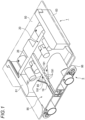
- Fig. 1 is a perspective view showing an inlet 1 as a second connector and an inlet plug 5 as a first connector to be fitted to the inlet 1, which constitute a connector fitting structure according to the embodiment of the present disclosure.
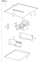
- Fig. 2 is an exploded perspective view of the inlet 1 shown in Fig. 1 .
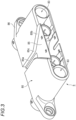
- Fig. 3 is a perspective view of the inlet plug 5 shown in Fig. 1 .
- a fitting guide groove 85 guide groove
- a plurality of recessed portions 191 are formed on front end sides of both side surfaces facing groove side surfaces of the fitting guide groove 85.
- the fitting guide groove 85 is provided in a plug housing 80 of the inlet plug 5.
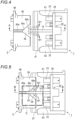
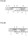
- a front-rear direction is a direction along a connector fitting direction (a left-right direction in Figs. 6A and 6B ) of the housing 20.
- a side where the plug housing 80 of the inlet plug 5 is fitted is defined as the front side.
- An upper-lower direction is a direction (an upper-lower direction in Figs. 6A and 6B ) orthogonal to the connector fitting direction of the housing 20.
- a top plate 50 side of the outer case 51 is defined as the upper side.
- the housing 20 of the inlet 1 is formed of an electrically insulating synthetic resin.
- a front wall 26 of the housing 20 is provided with a pair of terminal housing cylinder portions 23, 23 protruding toward the inlet plug 5 side.
- a connection terminal connected to a terminal portion of a high-voltage cable (not shown) is housed in the terminal housing cylinder portion 23.
- the high-voltage cable connected to the connection terminal is drawn out from a rear end opening of the terminal housing cylinder portion 23.
- a front surface opening 25 into which a connection terminal (first connection terminal) of the inlet plug 5 is inserted is formed at a front end of the terminal housing cylinder portion 23.
- connection terminal is a female terminal formed of a conductive metal material, and is formed in a cylindrical rod shape.
- a joint hole is formed in a rear end portion of the connection terminal, and a conductor of the high-voltage cable drawn out from the rear end opening of the terminal housing cylinder portion 23 is inserted into the joint hole and is crimped and connected to the joint hole.
- the outer case 51 is a flat housing formed by a bottom plate portion 57, side wall members 61, 63, and the top plate 50.
- the bottom plate portion 57 is a flat plate having a size slightly smaller than the top plate 50.
- the bottom plate portion 57 has an inclined portion, which guides the insertion of the inlet plug 5 into the inlet 1, on an upper surface of a front side end portion.
- the side wall members 61, 63 are disposed on both left and right sides of the housing 20, and serve as both side walls of the outer case 51.
- Each of the side wall members 61, 63 has a step portion at a substantially central position in the front-rear direction, with which both side end portions of the housing 20 are brought into contact.
- an eaves portion 15 extends in front of an upper wall portion 13 that defines a housing space together with the bottom plate portion 57 and the side wall members 61, 63.
- the pick-up rib 19 for guiding and fitting the plug housing 80 of the inlet plug 5 to the housing 20 housed in the outer case 51 extends along the connector fitting direction.
- the pick-up rib 19 has a substantially rectangular parallelepiped shape whose front end is rounded and whose length in the connector fitting direction is longer than the length in the left-right direction, and the plurality of recessed portions 191 are formed on both left and right side surfaces in a front side (front end side).
- the plurality of recessed portions 191 are formed in the pick-up rib 19 at predetermined intervals along the connector fitting direction from a front end of the pick-up rib 19.
- the predetermined interval is appropriately determined in consideration of a size of the pick-up rib 19, a size of the fitting guide groove 85, and the like.
- the recessed portions 191 have a sine wave shape in which a cross section in a plane along a groove bottom surface of the fitting guide groove 85 is a curved shape.
- the top plate 50, the pick-up rib 19, the side wall members 61, 63, and the bottom plate portion 57 are integrally formed of an electrically insulating synthetic resin.
- the housing 20 housing the connection terminal is inserted into the integrally molded outer case 51 from the rear side and screwed.
- the plug housing 80 is formed of an electrically insulating synthetic resin.
- the bracket 86 is attached to the plug housing 80.
- connection terminal 90 (see Figs. 6A and 6B ) connected to a terminal portion of a plug-side high-voltage cable (not shown) is housed in the terminal housing chamber 83.
- the plug-side high-voltage cable connected to the connection terminal 90 is drawn out from a rear end opening of the terminal housing chamber 83.
- connection terminal 90 shown in Figs. 6A and 6B is a male terminal formed of a conductive metal material, and is formed in a columnar rod shape.
- a joint hole is formed in a rear end portion of the connection terminal 90, and a conductor of the high-voltage cable drawn out from the rear end opening of the terminal housing chamber 83 is inserted into the joint hole and is crimped and connected to the joint hole.
- the inlet plug 5 is moved to the inlet 1 side, and the plug housing 80 starts to be inserted and fitted into the outer case 51.
- the upper surface of the plug housing 80 abuts on a lower surface of the top plate 50 of the inlet 1, and the front end of the pick-up rib 19 is inserted into the second groove portion 85b of the fitting guide groove 85.
- the front end of the pick-up rib 19 abuts on groove side surfaces of the second groove portion 85b in the fitting guide groove 85 in the state immediately after the start of fitting (see Fig. 4 ). From this state, when the inlet plug 5 is further deeply inserted so as to be advanced to the rear side of the inlet 1, the front end of the pick-up rib 19 reaches between both groove side surfaces of the connection portion 85c as shown in Fig. 7 while the side surfaces of the pick-up rib 19 are in sliding contact with the groove side surfaces of the second groove portion 85b of the fitting guide groove 85.
- the pick-up rib 19 is inserted between both groove side surfaces of the first groove portion 85a in the fitting guide groove 85.
- the plug housing 80 is fitted and guided to the housing 20 while the inclined fitting direction is corrected to the correct connector fitting direction.
- the connection terminal 90 of the inlet plug 5 is fitted and connected to the connection terminal of the inlet 1, and accordingly, the high-voltage cable on the inlet 1 side and the plug-side high-voltage cable are electrically connected.
- a shape of the pick-up rib 19 of the present embodiment and a shape of a pick-up rib 19A of the reference example will be compared.
- the shape of the pick-up rib 19 is indicated by a solid line
- the shape of the pick-up rib 19A is indicated by an alternate long and short dash line.
- the pick-up rib 19A of the reference example has a shape in which the recessed portion 191 is not provided in the pick-up rib 19 of the present embodiment. Since the pick-up rib 19A of the reference example interferes with the groove side surfaces of the connection portion 85c at a position indicated by a rectangular frame in Fig.
- the pick-up rib 19A is caught when the inlet plug 5 is inserted into the inlet 1.
- the pick-up rib 19 of the embodiment does not interfere with the connection portion 85c, the pick-up rib 19 does not catch the connection portion 85c.
- the recessed portions 191 are formed in the side surfaces of the pick-up rib 19.
- the connector fitting structure of the present embodiment is particularly useful when the inlet 1 and the inlet plug 5 are fitted to each other automatically or semi-automatically.
- the plurality of recessed portions 191 are formed on one side surface of the pick-up rib 19, even when an approach angle of the pick-up rib 19 is changed, interference with the connection portion 85c can be avoided in any of the recessed portions 191.
- the connector of the present disclosure is not limited thereto, and can be applied to various connectors based on a gist of the present disclosure.
- the plurality of recessed portions 191 are provided in both the side surfaces of the pick-up rib 19, at least one recessed portion 191 may be provided on the front end side of at least one side surface of the pick-up rib 19.
- the cross-sectional shape or the shape in the plan view of the recessed portion formed in the pick-up rib 19 is not limited to the curved shape, and may be formed by a bent straight line like the recessed portions 191 provided in a pick-up rib 19B shown in Fig. 10 .
- the pick-up rib 19 in which the recessed portions 191 are formed is provided on the inlet 1, and the fitting guide groove 85 is provided in the inlet plug 5, but the present disclosure is not limited to this configuration.
- One of two connectors to be fitted to each other may be provided with a projection portion corresponding to a pick-up rib in which a recessed portion is formed, and the other connector may be provided with a guide groove into which the projection portion is inserted.
Landscapes
- Details Of Connecting Devices For Male And Female Coupling (AREA)
- Connector Housings Or Holding Contact Members (AREA)
Claims (5)
- Verbinderbefestigungskonstruktion, mit:einem ersten Verbinder (5); undeinem zweiten Verbinder (1), wobeider erste Verbinder (5) und der zweite Verbinder (1) aneinander befestigt und elektrisch miteinander verbunden sind,der erste Verbinder (5) aufweist:ein erstes Gehäuse (80), das einen ersten Verbindungsanschluss enthält; undeine Führungsnut (85), die in dem ersten Gehäuse (80) vorgesehen ist, wobei die Führungsnut (85) aufweist:einen ersten Nutbereich (85a), der entlang einer Verbinderbefestigungsrichtung verläuft;einen zweiten Nutbereich (85b), der so ausgebildet ist, dass er ausgehend von einer Seite des ersten Nutbereichs in Richtung zu einer Seite des zweiten Verbinders nach und nach breiter wird; undeinen Verbindungsbereich (85c), der den ersten Nutbereich und den zweiten Nutbereich verbindet,der zweite Verbinder (1) aufweist:ein zweites Gehäuse (51), das einen zweiten Verbindungsanschluss enthält; undeinen Vorsprungsbereich (19), der an dem zweiten Gehäuse vorgesehen und in die Führungsnut eingeführt ist,dadurch gekennzeichnet, dassder Vorsprungsbereich (19) einen zurückgesetzten Bereich (191) aufweist, der an einer vorderen Stirnseite des Vorsprungsbereich und mindestens auf einer Seitenfläche des Vorsprungsbereichs, die Nutseitenflächen der Führungsnut zugewandt ist, ausgebildet ist.
- Verbinderbefestigungskonstruktion nach Anspruch 1, wobei
der zurückgesetzte Bereich (191) jeweils auf beiden Seitenflächen des Vorsprungsbereichs (19), die den Nutseitenflächen zugewandt sind, ausgebildet ist. - Verbinderbefestigungskonstruktion nach Anspruch 1 oder 2, wobeider zurückgesetzte Bereich (191) mehrere zurückgesetzte Bereiche (191) aufweist, unddie mehreren zurückgesetzten Bereiche (191) in dem Vorsprungsbereich für jeweils einen vorbestimmten Abstand entlang der Verbinderbefestigungsrichtung ausgehend von der Stirnflächenseite ausgebildet sind.
- Verbinderbefestigungskonstruktion nach einem der Ansprüche 1 bis 3, wobei eine Querschnittsform des zurückgesetzten Bereichs, die eben entlang einer Nutbodenfläche der Führungsnut (85) genommen ist, eine gekrümmte Form hat.
- Verbinderbefestigungskonstruktion nach Anspruch 4, wobei
die Querschnittsform auf der mindestens einen Seitenfläche des Vorsprungsbereichs (19) eine Sinuswellenform hat.
Applications Claiming Priority (1)
| Application Number | Priority Date | Filing Date | Title |
|---|---|---|---|
| JP2021111755A JP7680290B2 (ja) | 2021-07-05 | 2021-07-05 | コネクタ嵌合構造 |
Publications (2)
| Publication Number | Publication Date |
|---|---|
| EP4117123A1 EP4117123A1 (de) | 2023-01-11 |
| EP4117123B1 true EP4117123B1 (de) | 2023-05-31 |
Family
ID=82547563
Family Applications (1)
| Application Number | Title | Priority Date | Filing Date |
|---|---|---|---|
| EP22182631.6A Active EP4117123B1 (de) | 2021-07-05 | 2022-07-01 | Verbinderbefestigungskonstruktion |
Country Status (4)
| Country | Link |
|---|---|
| US (1) | US12266890B2 (de) |
| EP (1) | EP4117123B1 (de) |
| JP (1) | JP7680290B2 (de) |
| CN (1) | CN115588878B (de) |
Families Citing this family (2)
| Publication number | Priority date | Publication date | Assignee | Title |
|---|---|---|---|---|
| JP7680293B2 (ja) * | 2021-07-07 | 2025-05-20 | 矢崎総業株式会社 | コネクタ |
| JP7518130B2 (ja) * | 2022-06-30 | 2024-07-17 | 矢崎総業株式会社 | コネクタ嵌合構造 |
Family Cites Families (16)
| Publication number | Priority date | Publication date | Assignee | Title |
|---|---|---|---|---|
| JP3236762B2 (ja) * | 1995-09-21 | 2001-12-10 | 株式会社オートネットワーク技術研究所 | 車載用大型ユニットの固定構造 |
| JP3874987B2 (ja) * | 2000-03-01 | 2007-01-31 | 株式会社オートネットワーク技術研究所 | 車載用待ち受けコネクタの位置決め構造 |
| WO2008034134A2 (en) * | 2006-09-15 | 2008-03-20 | Amphenol Corporation | High density bayonet mating connector |
| US7530830B1 (en) * | 2007-07-19 | 2009-05-12 | Sunpower Corporation | Misalignment tolerant connector |
| JP4820421B2 (ja) * | 2009-01-13 | 2011-11-24 | ホシデン株式会社 | コネクタ |
| JP2013045521A (ja) * | 2011-08-22 | 2013-03-04 | Auto Network Gijutsu Kenkyusho:Kk | 電気接続装置およびコネクタ嵌合方法 |
| WO2013091920A1 (en) * | 2011-12-23 | 2013-06-27 | Delphi Connection Systems Holding France | Connector arrangement with self alignment |
| JP6200862B2 (ja) * | 2014-07-18 | 2017-09-20 | 株式会社日立製作所 | コネクタガイド機構 |
| JP6516144B2 (ja) * | 2015-01-30 | 2019-05-22 | 株式会社日立プラントコンストラクション | コネクタ接続ガイド、及びコネクタ接続ユニット |
| EP3288124B1 (de) * | 2015-04-21 | 2021-09-08 | Witco Of Jupiter Dentsu Co., Ltd. | Verbinder |
| DE202015003177U1 (de) * | 2015-04-30 | 2015-05-13 | Rosenberger Hochfrequenztechnik Gmbh & Co. Kg | Steckverbindung und Satz von Steckverbindungen |
| CN108352656B (zh) * | 2015-11-10 | 2020-04-21 | 株式会社自动网络技术研究所 | 连接器装置 |
| JP6997127B2 (ja) * | 2019-03-26 | 2022-01-17 | ヒロセ電機株式会社 | コネクタ装置およびコネクタ |
| CN109888563B (zh) * | 2019-04-18 | 2021-04-20 | 中国科学院地质与地球物理研究所 | 一种随钻仪器用多芯直插电连接结构 |
| FR3101205B1 (fr) * | 2019-09-20 | 2023-07-14 | Axon Cable Sa | Dispositif et Connecteur à rattrapage de jeu, dispositif de connexion, et ensemble comportant un tel dispositif |
| CN112838440B (zh) * | 2020-12-30 | 2021-12-14 | 惠州市普安电子有限公司 | 一种可进行气密性检测的通信连接器 |
-
2021
- 2021-07-05 JP JP2021111755A patent/JP7680290B2/ja active Active
-
2022
- 2022-06-29 CN CN202210759947.5A patent/CN115588878B/zh active Active
- 2022-06-29 US US17/852,885 patent/US12266890B2/en active Active
- 2022-07-01 EP EP22182631.6A patent/EP4117123B1/de active Active
Also Published As
| Publication number | Publication date |
|---|---|
| US20230006395A1 (en) | 2023-01-05 |
| CN115588878B (zh) | 2025-12-02 |
| US12266890B2 (en) | 2025-04-01 |
| CN115588878A (zh) | 2023-01-10 |
| JP2023008307A (ja) | 2023-01-19 |
| EP4117123A1 (de) | 2023-01-11 |
| JP7680290B2 (ja) | 2025-05-20 |
Similar Documents
| Publication | Publication Date | Title |
|---|---|---|
| EP1936749B1 (de) | Anschlusskontakt, Steckverbinder und Herstellungsverfahren | |
| JP3311997B2 (ja) | コネクタ | |
| JP6371368B2 (ja) | 直角ヘッダアセンブリ | |
| US9246260B2 (en) | Electrical connector | |
| US7364449B2 (en) | Joint connector block | |
| EP4117123B1 (de) | Verbinderbefestigungskonstruktion | |
| US20180131117A1 (en) | Joint connector | |
| US20250015529A1 (en) | Connector | |
| JP6847016B2 (ja) | 同軸ケーブル用コネクタ | |
| CN106257764A (zh) | 带定位板的连接器 | |
| US11095070B2 (en) | Electrical connector | |
| US20150087183A1 (en) | Connector terminal housing | |
| CN218997128U (zh) | 端子、电连接器、线束和车辆 | |
| US7607945B2 (en) | Connector | |
| EP3883069B1 (de) | Struktur zur befestigung eines verbinders | |
| JP7690438B2 (ja) | カプラ装置 | |
| JP7609085B2 (ja) | コネクタ | |
| US20080139039A1 (en) | Connector | |
| JP7811361B2 (ja) | コネクタ | |
| US12444891B2 (en) | Terminal fitting and connector | |
| JP2012028084A (ja) | コネクタ | |
| JP7198415B2 (ja) | カバー | |
| JP2023169934A (ja) | コネクタ | |
| WO2015099180A1 (ja) | コネクタ | |
| JP4194885B2 (ja) | 電気接続箱 |
Legal Events
| Date | Code | Title | Description |
|---|---|---|---|
| PUAI | Public reference made under article 153(3) epc to a published international application that has entered the european phase |
Free format text: ORIGINAL CODE: 0009012 |
|
| STAA | Information on the status of an ep patent application or granted ep patent |
Free format text: STATUS: REQUEST FOR EXAMINATION WAS MADE |
|
| 17P | Request for examination filed |
Effective date: 20220701 |
|
| AK | Designated contracting states |
Kind code of ref document: A1 Designated state(s): AL AT BE BG CH CY CZ DE DK EE ES FI FR GB GR HR HU IE IS IT LI LT LU LV MC MK MT NL NO PL PT RO RS SE SI SK SM TR |
|
| GRAP | Despatch of communication of intention to grant a patent |
Free format text: ORIGINAL CODE: EPIDOSNIGR1 |
|
| STAA | Information on the status of an ep patent application or granted ep patent |
Free format text: STATUS: GRANT OF PATENT IS INTENDED |
|
| GRAS | Grant fee paid |
Free format text: ORIGINAL CODE: EPIDOSNIGR3 |
|
| INTG | Intention to grant announced |
Effective date: 20230327 |
|
| GRAA | (expected) grant |
Free format text: ORIGINAL CODE: 0009210 |
|
| STAA | Information on the status of an ep patent application or granted ep patent |
Free format text: STATUS: THE PATENT HAS BEEN GRANTED |
|
| AK | Designated contracting states |
Kind code of ref document: B1 Designated state(s): AL AT BE BG CH CY CZ DE DK EE ES FI FR GB GR HR HU IE IS IT LI LT LU LV MC MK MT NL NO PL PT RO RS SE SI SK SM TR |
|
| REG | Reference to a national code |
Ref country code: GB Ref legal event code: FG4D Ref country code: CH Ref legal event code: EP |
|
| RAP4 | Party data changed (patent owner data changed or rights of a patent transferred) |
Owner name: YAZAKI CORPORATION |
|
| REG | Reference to a national code |
Ref country code: DE Ref legal event code: R096 Ref document number: 602022000097 Country of ref document: DE |
|
| REG | Reference to a national code |
Ref country code: AT Ref legal event code: REF Ref document number: 1571533 Country of ref document: AT Kind code of ref document: T Effective date: 20230615 |
|
| REG | Reference to a national code |
Ref country code: IE Ref legal event code: FG4D |
|
| REG | Reference to a national code |
Ref country code: LT Ref legal event code: MG9D |
|
| REG | Reference to a national code |
Ref country code: NL Ref legal event code: MP Effective date: 20230531 |
|
| REG | Reference to a national code |
Ref country code: AT Ref legal event code: MK05 Ref document number: 1571533 Country of ref document: AT Kind code of ref document: T Effective date: 20230531 |
|
| PG25 | Lapsed in a contracting state [announced via postgrant information from national office to epo] |
Ref country code: SE Free format text: LAPSE BECAUSE OF FAILURE TO SUBMIT A TRANSLATION OF THE DESCRIPTION OR TO PAY THE FEE WITHIN THE PRESCRIBED TIME-LIMIT Effective date: 20230531 Ref country code: NO Free format text: LAPSE BECAUSE OF FAILURE TO SUBMIT A TRANSLATION OF THE DESCRIPTION OR TO PAY THE FEE WITHIN THE PRESCRIBED TIME-LIMIT Effective date: 20230831 Ref country code: ES Free format text: LAPSE BECAUSE OF FAILURE TO SUBMIT A TRANSLATION OF THE DESCRIPTION OR TO PAY THE FEE WITHIN THE PRESCRIBED TIME-LIMIT Effective date: 20230531 Ref country code: AT Free format text: LAPSE BECAUSE OF FAILURE TO SUBMIT A TRANSLATION OF THE DESCRIPTION OR TO PAY THE FEE WITHIN THE PRESCRIBED TIME-LIMIT Effective date: 20230531 |
|
| PG25 | Lapsed in a contracting state [announced via postgrant information from national office to epo] |
Ref country code: RS Free format text: LAPSE BECAUSE OF FAILURE TO SUBMIT A TRANSLATION OF THE DESCRIPTION OR TO PAY THE FEE WITHIN THE PRESCRIBED TIME-LIMIT Effective date: 20230531 Ref country code: PL Free format text: LAPSE BECAUSE OF FAILURE TO SUBMIT A TRANSLATION OF THE DESCRIPTION OR TO PAY THE FEE WITHIN THE PRESCRIBED TIME-LIMIT Effective date: 20230531 Ref country code: NL Free format text: LAPSE BECAUSE OF FAILURE TO SUBMIT A TRANSLATION OF THE DESCRIPTION OR TO PAY THE FEE WITHIN THE PRESCRIBED TIME-LIMIT Effective date: 20230531 Ref country code: LV Free format text: LAPSE BECAUSE OF FAILURE TO SUBMIT A TRANSLATION OF THE DESCRIPTION OR TO PAY THE FEE WITHIN THE PRESCRIBED TIME-LIMIT Effective date: 20230531 Ref country code: LT Free format text: LAPSE BECAUSE OF FAILURE TO SUBMIT A TRANSLATION OF THE DESCRIPTION OR TO PAY THE FEE WITHIN THE PRESCRIBED TIME-LIMIT Effective date: 20230531 Ref country code: IS Free format text: LAPSE BECAUSE OF FAILURE TO SUBMIT A TRANSLATION OF THE DESCRIPTION OR TO PAY THE FEE WITHIN THE PRESCRIBED TIME-LIMIT Effective date: 20230930 Ref country code: HR Free format text: LAPSE BECAUSE OF FAILURE TO SUBMIT A TRANSLATION OF THE DESCRIPTION OR TO PAY THE FEE WITHIN THE PRESCRIBED TIME-LIMIT Effective date: 20230531 Ref country code: GR Free format text: LAPSE BECAUSE OF FAILURE TO SUBMIT A TRANSLATION OF THE DESCRIPTION OR TO PAY THE FEE WITHIN THE PRESCRIBED TIME-LIMIT Effective date: 20230901 |
|
| PG25 | Lapsed in a contracting state [announced via postgrant information from national office to epo] |
Ref country code: FI Free format text: LAPSE BECAUSE OF FAILURE TO SUBMIT A TRANSLATION OF THE DESCRIPTION OR TO PAY THE FEE WITHIN THE PRESCRIBED TIME-LIMIT Effective date: 20230531 |
|
| PG25 | Lapsed in a contracting state [announced via postgrant information from national office to epo] |
Ref country code: SK Free format text: LAPSE BECAUSE OF FAILURE TO SUBMIT A TRANSLATION OF THE DESCRIPTION OR TO PAY THE FEE WITHIN THE PRESCRIBED TIME-LIMIT Effective date: 20230531 |
|
| PG25 | Lapsed in a contracting state [announced via postgrant information from national office to epo] |
Ref country code: SM Free format text: LAPSE BECAUSE OF FAILURE TO SUBMIT A TRANSLATION OF THE DESCRIPTION OR TO PAY THE FEE WITHIN THE PRESCRIBED TIME-LIMIT Effective date: 20230531 Ref country code: SK Free format text: LAPSE BECAUSE OF FAILURE TO SUBMIT A TRANSLATION OF THE DESCRIPTION OR TO PAY THE FEE WITHIN THE PRESCRIBED TIME-LIMIT Effective date: 20230531 Ref country code: RO Free format text: LAPSE BECAUSE OF FAILURE TO SUBMIT A TRANSLATION OF THE DESCRIPTION OR TO PAY THE FEE WITHIN THE PRESCRIBED TIME-LIMIT Effective date: 20230531 Ref country code: PT Free format text: LAPSE BECAUSE OF FAILURE TO SUBMIT A TRANSLATION OF THE DESCRIPTION OR TO PAY THE FEE WITHIN THE PRESCRIBED TIME-LIMIT Effective date: 20231002 Ref country code: EE Free format text: LAPSE BECAUSE OF FAILURE TO SUBMIT A TRANSLATION OF THE DESCRIPTION OR TO PAY THE FEE WITHIN THE PRESCRIBED TIME-LIMIT Effective date: 20230531 Ref country code: DK Free format text: LAPSE BECAUSE OF FAILURE TO SUBMIT A TRANSLATION OF THE DESCRIPTION OR TO PAY THE FEE WITHIN THE PRESCRIBED TIME-LIMIT Effective date: 20230531 Ref country code: CZ Free format text: LAPSE BECAUSE OF FAILURE TO SUBMIT A TRANSLATION OF THE DESCRIPTION OR TO PAY THE FEE WITHIN THE PRESCRIBED TIME-LIMIT Effective date: 20230531 |
|
| PG25 | Lapsed in a contracting state [announced via postgrant information from national office to epo] |
Ref country code: MC Free format text: LAPSE BECAUSE OF FAILURE TO SUBMIT A TRANSLATION OF THE DESCRIPTION OR TO PAY THE FEE WITHIN THE PRESCRIBED TIME-LIMIT Effective date: 20230531 |
|
| PG25 | Lapsed in a contracting state [announced via postgrant information from national office to epo] |
Ref country code: MC Free format text: LAPSE BECAUSE OF FAILURE TO SUBMIT A TRANSLATION OF THE DESCRIPTION OR TO PAY THE FEE WITHIN THE PRESCRIBED TIME-LIMIT Effective date: 20230531 |
|
| REG | Reference to a national code |
Ref country code: DE Ref legal event code: R097 Ref document number: 602022000097 Country of ref document: DE |
|
| PLBE | No opposition filed within time limit |
Free format text: ORIGINAL CODE: 0009261 |
|
| STAA | Information on the status of an ep patent application or granted ep patent |
Free format text: STATUS: NO OPPOSITION FILED WITHIN TIME LIMIT |
|
| PG25 | Lapsed in a contracting state [announced via postgrant information from national office to epo] |
Ref country code: SI Free format text: LAPSE BECAUSE OF FAILURE TO SUBMIT A TRANSLATION OF THE DESCRIPTION OR TO PAY THE FEE WITHIN THE PRESCRIBED TIME-LIMIT Effective date: 20230531 |
|
| 26N | No opposition filed |
Effective date: 20240301 |
|
| PG25 | Lapsed in a contracting state [announced via postgrant information from national office to epo] |
Ref country code: SI Free format text: LAPSE BECAUSE OF FAILURE TO SUBMIT A TRANSLATION OF THE DESCRIPTION OR TO PAY THE FEE WITHIN THE PRESCRIBED TIME-LIMIT Effective date: 20230531 Ref country code: IT Free format text: LAPSE BECAUSE OF FAILURE TO SUBMIT A TRANSLATION OF THE DESCRIPTION OR TO PAY THE FEE WITHIN THE PRESCRIBED TIME-LIMIT Effective date: 20230531 Ref country code: FR Free format text: LAPSE BECAUSE OF NON-PAYMENT OF DUE FEES Effective date: 20230731 |
|
| PG25 | Lapsed in a contracting state [announced via postgrant information from national office to epo] |
Ref country code: BG Free format text: LAPSE BECAUSE OF FAILURE TO SUBMIT A TRANSLATION OF THE DESCRIPTION OR TO PAY THE FEE WITHIN THE PRESCRIBED TIME-LIMIT Effective date: 20230531 |
|
| PG25 | Lapsed in a contracting state [announced via postgrant information from national office to epo] |
Ref country code: BG Free format text: LAPSE BECAUSE OF FAILURE TO SUBMIT A TRANSLATION OF THE DESCRIPTION OR TO PAY THE FEE WITHIN THE PRESCRIBED TIME-LIMIT Effective date: 20230531 |
|
| PG25 | Lapsed in a contracting state [announced via postgrant information from national office to epo] |
Ref country code: LU Free format text: LAPSE BECAUSE OF NON-PAYMENT OF DUE FEES Effective date: 20240701 |
|
| PG25 | Lapsed in a contracting state [announced via postgrant information from national office to epo] |
Ref country code: LU Free format text: LAPSE BECAUSE OF NON-PAYMENT OF DUE FEES Effective date: 20240701 |
|
| PG25 | Lapsed in a contracting state [announced via postgrant information from national office to epo] |
Ref country code: BE Free format text: LAPSE BECAUSE OF NON-PAYMENT OF DUE FEES Effective date: 20240731 |
|
| REG | Reference to a national code |
Ref country code: BE Ref legal event code: MM Effective date: 20240731 |
|
| PG25 | Lapsed in a contracting state [announced via postgrant information from national office to epo] |
Ref country code: IE Free format text: LAPSE BECAUSE OF NON-PAYMENT OF DUE FEES Effective date: 20240701 |
|
| PGFP | Annual fee paid to national office [announced via postgrant information from national office to epo] |
Ref country code: DE Payment date: 20250528 Year of fee payment: 4 |
|
| PG25 | Lapsed in a contracting state [announced via postgrant information from national office to epo] |
Ref country code: CY Free format text: LAPSE BECAUSE OF FAILURE TO SUBMIT A TRANSLATION OF THE DESCRIPTION OR TO PAY THE FEE WITHIN THE PRESCRIBED TIME-LIMIT; INVALID AB INITIO Effective date: 20220701 |
|
| PG25 | Lapsed in a contracting state [announced via postgrant information from national office to epo] |
Ref country code: TR Free format text: LAPSE BECAUSE OF FAILURE TO SUBMIT A TRANSLATION OF THE DESCRIPTION OR TO PAY THE FEE WITHIN THE PRESCRIBED TIME-LIMIT Effective date: 20230531 |
|
| REG | Reference to a national code |
Ref country code: CH Ref legal event code: H13 Free format text: ST27 STATUS EVENT CODE: U-0-0-H10-H13 (AS PROVIDED BY THE NATIONAL OFFICE) Effective date: 20260224 |
|
| PG25 | Lapsed in a contracting state [announced via postgrant information from national office to epo] |
Ref country code: HU Free format text: LAPSE BECAUSE OF FAILURE TO SUBMIT A TRANSLATION OF THE DESCRIPTION OR TO PAY THE FEE WITHIN THE PRESCRIBED TIME-LIMIT; INVALID AB INITIO Effective date: 20220701 |
|
| PG25 | Lapsed in a contracting state [announced via postgrant information from national office to epo] |
Ref country code: CH Free format text: LAPSE BECAUSE OF NON-PAYMENT OF DUE FEES Effective date: 20250731 |