EP4117497B1 - Robot nettoyeur et son procédé de commande - Google Patents
Robot nettoyeur et son procédé de commande Download PDFInfo
- Publication number
- EP4117497B1 EP4117497B1 EP20924565.3A EP20924565A EP4117497B1 EP 4117497 B1 EP4117497 B1 EP 4117497B1 EP 20924565 A EP20924565 A EP 20924565A EP 4117497 B1 EP4117497 B1 EP 4117497B1
- Authority
- EP
- European Patent Office
- Prior art keywords
- image
- camera
- sensor
- robot cleaner
- singularity
- Prior art date
- Legal status (The legal status is an assumption and is not a legal conclusion. Google has not performed a legal analysis and makes no representation as to the accuracy of the status listed.)
- Active
Links
Images

Classifications
-
- A—HUMAN NECESSITIES
- A47—FURNITURE; DOMESTIC ARTICLES OR APPLIANCES; COFFEE MILLS; SPICE MILLS; SUCTION CLEANERS IN GENERAL
- A47L—DOMESTIC WASHING OR CLEANING; SUCTION CLEANERS IN GENERAL
- A47L9/00—Details or accessories of suction cleaners, e.g. mechanical means for controlling the suction or for effecting pulsating action; Storing devices specially adapted to suction cleaners or parts thereof; Carrying-vehicles specially adapted for suction cleaners
- A47L9/28—Installation of the electric equipment, e.g. adaptation or attachment to the suction cleaner; Controlling suction cleaners by electric means
- A47L9/2805—Parameters or conditions being sensed
- A47L9/2826—Parameters or conditions being sensed the condition of the floor
-
- A—HUMAN NECESSITIES
- A47—FURNITURE; DOMESTIC ARTICLES OR APPLIANCES; COFFEE MILLS; SPICE MILLS; SUCTION CLEANERS IN GENERAL
- A47L—DOMESTIC WASHING OR CLEANING; SUCTION CLEANERS IN GENERAL
- A47L9/00—Details or accessories of suction cleaners, e.g. mechanical means for controlling the suction or for effecting pulsating action; Storing devices specially adapted to suction cleaners or parts thereof; Carrying-vehicles specially adapted for suction cleaners
- A47L9/28—Installation of the electric equipment, e.g. adaptation or attachment to the suction cleaner; Controlling suction cleaners by electric means
-
- A—HUMAN NECESSITIES
- A47—FURNITURE; DOMESTIC ARTICLES OR APPLIANCES; COFFEE MILLS; SPICE MILLS; SUCTION CLEANERS IN GENERAL
- A47L—DOMESTIC WASHING OR CLEANING; SUCTION CLEANERS IN GENERAL
- A47L9/00—Details or accessories of suction cleaners, e.g. mechanical means for controlling the suction or for effecting pulsating action; Storing devices specially adapted to suction cleaners or parts thereof; Carrying-vehicles specially adapted for suction cleaners
- A47L9/28—Installation of the electric equipment, e.g. adaptation or attachment to the suction cleaner; Controlling suction cleaners by electric means
- A47L9/2836—Installation of the electric equipment, e.g. adaptation or attachment to the suction cleaner; Controlling suction cleaners by electric means characterised by the parts which are controlled
- A47L9/2852—Elements for displacement of the vacuum cleaner or the accessories therefor, e.g. wheels, casters or nozzles
-
- B—PERFORMING OPERATIONS; TRANSPORTING
- B25—HAND TOOLS; PORTABLE POWER-DRIVEN TOOLS; MANIPULATORS
- B25J—MANIPULATORS; CHAMBERS PROVIDED WITH MANIPULATION DEVICES
- B25J11/00—Manipulators not otherwise provided for
- B25J11/008—Manipulators for service tasks
- B25J11/0085—Cleaning
-
- B—PERFORMING OPERATIONS; TRANSPORTING
- B25—HAND TOOLS; PORTABLE POWER-DRIVEN TOOLS; MANIPULATORS
- B25J—MANIPULATORS; CHAMBERS PROVIDED WITH MANIPULATION DEVICES
- B25J19/00—Accessories fitted to manipulators, e.g. for monitoring, for viewing; Safety devices combined with or specially adapted for use in connection with manipulators
- B25J19/02—Sensing devices
- B25J19/021—Optical sensing devices
- B25J19/023—Optical sensing devices including video camera means
-
- B—PERFORMING OPERATIONS; TRANSPORTING
- B25—HAND TOOLS; PORTABLE POWER-DRIVEN TOOLS; MANIPULATORS
- B25J—MANIPULATORS; CHAMBERS PROVIDED WITH MANIPULATION DEVICES
- B25J9/00—Program-controlled manipulators
- B25J9/16—Program controls
- B25J9/1656—Program controls characterised by programming, planning systems for manipulators
- B25J9/1664—Program controls characterised by programming, planning systems for manipulators characterised by motion, path, trajectory planning
- B25J9/1666—Avoiding collision or forbidden zones
-
- B—PERFORMING OPERATIONS; TRANSPORTING
- B25—HAND TOOLS; PORTABLE POWER-DRIVEN TOOLS; MANIPULATORS
- B25J—MANIPULATORS; CHAMBERS PROVIDED WITH MANIPULATION DEVICES
- B25J9/00—Program-controlled manipulators
- B25J9/16—Program controls
- B25J9/1674—Program controls characterised by safety, monitoring, diagnostic
- B25J9/1676—Avoiding collision or forbidden zones
-
- G—PHYSICS
- G05—CONTROLLING; REGULATING
- G05D—SYSTEMS FOR CONTROLLING OR REGULATING NON-ELECTRIC VARIABLES
- G05D1/00—Control of position, course, altitude or attitude of land, water, air or space vehicles, e.g. using automatic pilots
- G05D1/02—Control of position or course in two dimensions
- G05D1/021—Control of position or course in two dimensions specially adapted to land vehicles
- G05D1/0212—Control of position or course in two dimensions specially adapted to land vehicles with means for defining a desired trajectory
- G05D1/0214—Control of position or course in two dimensions specially adapted to land vehicles with means for defining a desired trajectory in accordance with safety or protection criteria, e.g. avoiding hazardous areas
-
- G—PHYSICS
- G05—CONTROLLING; REGULATING
- G05D—SYSTEMS FOR CONTROLLING OR REGULATING NON-ELECTRIC VARIABLES
- G05D1/00—Control of position, course, altitude or attitude of land, water, air or space vehicles, e.g. using automatic pilots
- G05D1/02—Control of position or course in two dimensions
- G05D1/021—Control of position or course in two dimensions specially adapted to land vehicles
- G05D1/0212—Control of position or course in two dimensions specially adapted to land vehicles with means for defining a desired trajectory
- G05D1/0221—Control of position or course in two dimensions specially adapted to land vehicles with means for defining a desired trajectory involving a learning process
-
- G—PHYSICS
- G05—CONTROLLING; REGULATING
- G05D—SYSTEMS FOR CONTROLLING OR REGULATING NON-ELECTRIC VARIABLES
- G05D1/00—Control of position, course, altitude or attitude of land, water, air or space vehicles, e.g. using automatic pilots
- G05D1/02—Control of position or course in two dimensions
- G05D1/021—Control of position or course in two dimensions specially adapted to land vehicles
- G05D1/0231—Control of position or course in two dimensions specially adapted to land vehicles using optical position detecting means
- G05D1/0238—Control of position or course in two dimensions specially adapted to land vehicles using optical position detecting means using obstacle or wall sensors
-
- G—PHYSICS
- G05—CONTROLLING; REGULATING
- G05D—SYSTEMS FOR CONTROLLING OR REGULATING NON-ELECTRIC VARIABLES
- G05D1/00—Control of position, course, altitude or attitude of land, water, air or space vehicles, e.g. using automatic pilots
- G05D1/02—Control of position or course in two dimensions
- G05D1/021—Control of position or course in two dimensions specially adapted to land vehicles
- G05D1/0231—Control of position or course in two dimensions specially adapted to land vehicles using optical position detecting means
- G05D1/0242—Control of position or course in two dimensions specially adapted to land vehicles using optical position detecting means using non-visible light signals, e.g. IR or UV signals
-
- G—PHYSICS
- G05—CONTROLLING; REGULATING
- G05D—SYSTEMS FOR CONTROLLING OR REGULATING NON-ELECTRIC VARIABLES
- G05D1/00—Control of position, course, altitude or attitude of land, water, air or space vehicles, e.g. using automatic pilots
- G05D1/02—Control of position or course in two dimensions
- G05D1/021—Control of position or course in two dimensions specially adapted to land vehicles
- G05D1/0231—Control of position or course in two dimensions specially adapted to land vehicles using optical position detecting means
- G05D1/0246—Control of position or course in two dimensions specially adapted to land vehicles using optical position detecting means using a video camera in combination with image processing means
-
- G—PHYSICS
- G05—CONTROLLING; REGULATING
- G05D—SYSTEMS FOR CONTROLLING OR REGULATING NON-ELECTRIC VARIABLES
- G05D1/00—Control of position, course, altitude or attitude of land, water, air or space vehicles, e.g. using automatic pilots
- G05D1/02—Control of position or course in two dimensions
- G05D1/021—Control of position or course in two dimensions specially adapted to land vehicles
- G05D1/0231—Control of position or course in two dimensions specially adapted to land vehicles using optical position detecting means
- G05D1/0246—Control of position or course in two dimensions specially adapted to land vehicles using optical position detecting means using a video camera in combination with image processing means
- G05D1/0251—Control of position or course in two dimensions specially adapted to land vehicles using optical position detecting means using a video camera in combination with image processing means extracting 3D information from a plurality of images taken from different locations, e.g. stereo vision
-
- G—PHYSICS
- G05—CONTROLLING; REGULATING
- G05D—SYSTEMS FOR CONTROLLING OR REGULATING NON-ELECTRIC VARIABLES
- G05D1/00—Control of position, course, altitude or attitude of land, water, air or space vehicles, e.g. using automatic pilots
- G05D1/20—Control system inputs
- G05D1/24—Arrangements for determining position or orientation
- G05D1/243—Means capturing signals occurring naturally from the environment, e.g. ambient optical, acoustic, gravitational or magnetic signals
- G05D1/2435—Extracting 3D information
-
- G—PHYSICS
- G05—CONTROLLING; REGULATING
- G05D—SYSTEMS FOR CONTROLLING OR REGULATING NON-ELECTRIC VARIABLES
- G05D1/00—Control of position, course, altitude or attitude of land, water, air or space vehicles, e.g. using automatic pilots
- G05D1/20—Control system inputs
- G05D1/24—Arrangements for determining position or orientation
- G05D1/247—Arrangements for determining position or orientation using signals provided by artificial sources external to the vehicle, e.g. navigation beacons
- G05D1/249—Arrangements for determining position or orientation using signals provided by artificial sources external to the vehicle, e.g. navigation beacons from positioning sensors located off-board the vehicle, e.g. from cameras
-
- G—PHYSICS
- G05—CONTROLLING; REGULATING
- G05D—SYSTEMS FOR CONTROLLING OR REGULATING NON-ELECTRIC VARIABLES
- G05D1/00—Control of position, course, altitude or attitude of land, water, air or space vehicles, e.g. using automatic pilots
- G05D1/60—Intended control result
- G05D1/617—Safety or protection, e.g. defining protection zones around obstacles or avoiding hazards
- G05D1/622—Obstacle avoidance
-
- H—ELECTRICITY
- H04—ELECTRIC COMMUNICATION TECHNIQUE
- H04N—PICTORIAL COMMUNICATION, e.g. TELEVISION
- H04N23/00—Cameras or camera modules comprising electronic image sensors; Control thereof
- H04N23/10—Cameras or camera modules comprising electronic image sensors; Control thereof for generating image signals from different wavelengths
- H04N23/12—Cameras or camera modules comprising electronic image sensors; Control thereof for generating image signals from different wavelengths with one sensor only
-
- H—ELECTRICITY
- H04—ELECTRIC COMMUNICATION TECHNIQUE
- H04N—PICTORIAL COMMUNICATION, e.g. TELEVISION
- H04N23/00—Cameras or camera modules comprising electronic image sensors; Control thereof
- H04N23/57—Mechanical or electrical details of cameras or camera modules specially adapted for being embedded in other devices
-
- A—HUMAN NECESSITIES
- A47—FURNITURE; DOMESTIC ARTICLES OR APPLIANCES; COFFEE MILLS; SPICE MILLS; SUCTION CLEANERS IN GENERAL
- A47L—DOMESTIC WASHING OR CLEANING; SUCTION CLEANERS IN GENERAL
- A47L2201/00—Robotic cleaning machines, i.e. with automatic control of the travelling movement or the cleaning operation
- A47L2201/04—Automatic control of the travelling movement; Automatic obstacle detection
-
- G—PHYSICS
- G05—CONTROLLING; REGULATING
- G05D—SYSTEMS FOR CONTROLLING OR REGULATING NON-ELECTRIC VARIABLES
- G05D2101/00—Details of software or hardware architectures used for the control of position
- G05D2101/10—Details of software or hardware architectures used for the control of position using artificial intelligence [AI] techniques
- G05D2101/15—Details of software or hardware architectures used for the control of position using artificial intelligence [AI] techniques using machine learning, e.g. neural networks
-
- G—PHYSICS
- G05—CONTROLLING; REGULATING
- G05D—SYSTEMS FOR CONTROLLING OR REGULATING NON-ELECTRIC VARIABLES
- G05D2105/00—Specific applications of the controlled vehicles
- G05D2105/10—Specific applications of the controlled vehicles for cleaning, vacuuming or polishing
-
- G—PHYSICS
- G05—CONTROLLING; REGULATING
- G05D—SYSTEMS FOR CONTROLLING OR REGULATING NON-ELECTRIC VARIABLES
- G05D2111/00—Details of signals used for control of position, course, altitude or attitude of land, water, air or space vehicles
- G05D2111/10—Optical signals
- G05D2111/14—Non-visible signals, e.g. IR or UV signals
Definitions
- the present disclosure relates to a robot cleaner and a method for controlling the same, and more particularly, to a robot cleaner and a method for controlling the same capable of accurately identifying an obstacle using a depth image and a 2-dimensional image and avoiding the obstacle.
- robots have been developed for industrial use and have been responsible for a part of factory automation.
- fields to which robots are applied have been further expanded, so that medical robots, aerospace robots, and the like have been developed, and household robots that may be used in general homes are also being made.
- a representative example of the household robot is a robot cleaner, which is a kind of home appliance that sucks surrounding dust or foreign matter to perform cleaning while traveling by itself in a certain region.
- a robot cleaner is generally equipped with a rechargeable battery and an obstacle sensor for avoiding an obstacle while traveling, so that the robot cleaner may perform the cleaning while traveling by itself.
- Korean Patent Publication Application No. 10-2014-0011216 which is a prior art, discloses a technology of capturing a floor image and automatically sensing whether a material of a floor is a material similar to a carpet or the like or a material similar to a floor paper or the like.
- a material of a floor is a material similar to a carpet or the like or a material similar to a floor paper or the like.
- US 2020/019181 A1 presents a robot cleaner for avoiding a stuck situation using artificial intelligence includes a sensing unit configured to detect the stuck situation of the robot cleaner, a driving unit to drive the robot cleaner, and a processor configured to determine a rotation angle of the robot cleaner when the stuck situation is detected through the sensing unit, control the driving unit such that the robot cleaner rotates by the determined rotation angle, and control the driving unit such that the robot cleaner reverses by a certain distance after rotating by the rotation angle.
- EP 3 308 911 A1 presents a moving robot includes a main body, a driving unit moving the main body, a camera installed on one side of the main body and capturing an image related to a marker, a memory storing information related to a pattern of the marker, and a controller extracting information related to at least one longitudinal line segment included in an appearance of the marker from the captured image, detecting information related to a position and a posture of the main body on the basis of the extracted information related to at least one of the longitudinal line segment and the pattern, and controlling the driving unit on the basis of at least one of the detected position and posture of the main body.
- JP 2019 171017 A presents an autonomous mobile cleaner that comprises: a drive part for driving movement of a cleaner body; a control part arranged on the cleaner body; a camera for acquiring a camera image in a front direction of the cleaner body; an obstacle detection sensor for detecting an object; and a rotation number sensor for detecting the movement impossible state.
- the control circuit is configured to identify information of an object which became in the movement impossible state, receive information of whether or not to set the object to a cleaning object, receive information indicating that the object is set to the cleaning object, and the control circuit controls the drive part and suction part so as to clean in a first movement mode for cleaning a space except for the object, and then getting over the object in cleaning reservation, and clean in a second movement mode for getting over the object first, and then cleaning the space except for the object in the cleaning start time.
- the present disclosure is to solve the above problems, and the present disclosure is to provide a robot cleaner and a method for controlling the same capable of accurately sensing an obstacle by supplementing an unclear portion in a captured depth image with a camera image.
- the present disclosure is to provide a robot cleaner and a method for controlling the same capable of determining a thin obstacle such as a wire and avoiding the corresponding obstacle.
- the present disclosure provides a robot cleaner and a method for controlling the same that may supplement a portion in a depth image in which it is difficult to identify whether an obstacle is recognized because of noise or diffused reflection/absorption resulted from a small size with color or brightness information of an IR image or an RGB image, thereby avoiding an obstacle.
- the present disclosure acquires brightness or color information of some sensed points in the depth image from the IR image or the RGB image, then expands the sensed points through the brightness or color information of the acquired points, and then combines the expanded points with a slightly sensed depth image detection result to secure enough volume to be recognized as the obstacle.
- the present disclosure provides a method for controlling a robot cleaner including acquiring, by a camera, an image, irradiating, by a light source, light toward a location the same as a location where the acquired image is captured, receiving, by a sensor, the light irradiated from the light source and reflected on an object, processing an image received from the sensor to contain a distance value of an individual location, and supplementing the image received from the sensor with the image captured by the camera when a singularity is found, wherein distance values calculated in adjacent portions are discontinuous at the singularity.
- the present disclosure provides a robot cleaner including a camera for acquiring an image, a light source for irradiating light toward a location the same as a location where the acquired image is captured, a sensor for sensing that the light irradiated from the light source is reflected, and a controller that processes an image using the light sensed by the sensor to calculate a distance value of an individual location in the corresponding image, wherein the image is supplemented with the image acquired by the camera when a singularity is found, wherein distance values calculated in adjacent portions are discontinuous at the singularity.
- the unclear portion in the captured depth image may be supplemented with the camera image, so that the obstacle may be accurately sensed. Therefore, a sensing accuracy of the obstacle may be improved.
- the thin obstacle such as the wire may be sensed, so that the robot cleaner may travel while avoiding the corresponding obstacle, thereby preventing a damage of the robot cleaner.
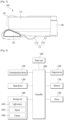
- a robot cleaner 100 performs a function of cleaning a floor while traveling by itself in a certain region.
- the cleaning of the floor referred herein includes sucking dust (including foreign matter) from the floor or mopping the floor.
- the robot cleaner 100 includes a cleaner body 110, a suction unit 120, a sensing unit 130, and a dust collection vessel 140.
- the cleaner body 110 includes a controller (not shown) for controlling the robot cleaner 100 and a wheel unit 111 for the traveling of the robot cleaner 100.
- the robot cleaner 100 may be moved back and forth and left and right, or rotated by the wheel unit 111.
- the wheel unit 111 includes main wheels 111a and sub-wheels 111b.
- the main wheels 111a may be respectively arranged on both sides of the cleaner body 110 to rotate in one direction or the other direction in response to a control signal of the controller.
- the main wheels 111a may be driven independently of each other.
- the main wheels 111a may be respectively driven by different motors.
- the sub-wheels 111b support the cleaner body 110 together with the main wheels 111a, and assist the traveling of the robot cleaner 100 by the main wheels 111a. Such sub-wheels 111b may also be arranged in the suction unit 120 to be described later.
- the controller controls the driving of the wheel unit 111, the robot cleaner 100 autonomously travels on the floor.
- the cleaner body 110 is equipped with a battery (not shown) that supplies power to the robot cleaner 100.
- the battery may be rechargeable and detachable from a bottom face of the cleaner body 110.
- the suction unit 120 is disposed to protrude from one side of the cleaner body 110 and sucks air containing dust.
- the one side may be a side on which the cleaner body 110 travels in a forward direction F, that is, a front side of the cleaner body 110.
- the suction unit 120 may be detachably coupled to the cleaner body 110.
- a mop module (not shown) may be detachably coupled to the cleaner body 110 by replacing the separated suction unit 120. Therefore, when a user wants to remove the dust from the floor, the user may mount the suction unit 120 on the cleaner body 110. In addition, when the user wants to mop the floor, the user may mount the mop module on the cleaner body 110.
- the sensing unit 130 is disposed on the cleaner body 110. As shown, the sensing unit 130 may be disposed on the one side of the cleaner body 110 where the suction unit 120 is located, that is, the front side of the cleaner body 110.
- the sensing unit 130 may be disposed to overlap the suction unit 120 in a vertical direction of the cleaner body 110.
- the sensing unit 130 is disposed above the suction unit 120 to sense an obstacle, a terrain object, or the like located in front of the robot cleaner such that the suction unit 120 located at the frontmost portion of the robot cleaner 100 does not collide with the obstacle.
- the sensing unit 130 additionally performs another sensing function in addition to such sensing function. This will be described in detail later.
- the robot cleaner 100 may include at least one of a communication device 1100, an input device 1200, a driver 1300, a sensing unit 1400, an output device 1500, a power unit 1600, a memory 1700, and a controller 1800, or a combination thereof.
- FIG. 4 the components shown in FIG. 4 are not essential, so that a robot cleaner having more or fewer components than that may be implemented.
- a robot cleaner having more or fewer components than that may be implemented.
- each of the component will be described.
- the power supply 1600 includes a battery that may be charged by an external commercial power source to supply power into the mobile robot.
- the power supply 1600 may supply driving power to each of the components included in the mobile robot, thereby supplying operation power required for the mobile robot to travel or perform a specific function.
- the controller 1800 may sense a remaining power of the battery, and control the mobile robot to move to the charging device connected to the external commercial power source when the remaining power is insufficient, thereby charging the battery by receiving charging current from the charging device.
- the battery may be connected to a battery sensor, so that the remaining power of the battery and a state of charge may be transmitted to the controller 1800.
- the output device 1500 may display the remaining power of the battery on a screen by the controller.
- the battery may be located at a lower portion of a center of the robot cleaner or may be located on one of left and right sides. In the latter case, the mobile robot may further include a counterweight to eliminate weight bias of the battery.
- the controller 1800 plays a role of processing information based on an artificial intelligence technology, which may include at least one module that performs at least one of learning of information, inference of information, perception of information, and processing of natural language.
- the controller 1800 may use a machine learning technology to perform at least one of the learning, the inference, and the processing of a vast amount of information (big data) such as information stored in the cleaner, surrounding environment information, and information stored in an external communicable storage.
- the controller 1800 may predict (or infer) one or more executable operations of the cleaner using the information learned using the machine learning technology, and control the cleaner such that an operation with the highest realization among the one or more predicted operations is executed.
- the machine learning technology is a technology, based on at least one algorithm, of collecting and learning large-scale information, and determining and predicting information based on the learned information.
- the learning of the information is an operation of quantifying a relationship between information and information by identifying characteristics, rules, and criteria of determination of the information, and predicting new data using a quantified pattern.
- An algorithm used in the machine learning technology may be an algorithm based on statistics, and may be, for example, a decision tree that uses a tree structure as a prediction model, an artificial neural network that mimics a structure and a function of a neural network of a living thing, genetic programming based on an evolution algorithm of the living thing, clustering that distributes observed examples into subsets called clusters, a Monte Carlo method that calculates function values with probability through randomly extracted random numbers, and the like.
- a deep learning technology is a technology of performing at least one of the learning, the determination, and the processing of the information using an artificial neural network (deep neuron network, DNN) algorithm.
- the artificial neural network (DNN) may have a structure of connecting layers with each other and transferring data between the layers.
- Such deep learning technology may learn a vast amount of information through the artificial neural network (DNN) using a graphic processing unit (GPU) optimized for parallel computation.
- GPU graphic processing unit
- the controller 1800 may use training data stored in an external server or in the memory, and may be equipped with a learning engine that detects features for recognizing a predetermined object.
- the features for recognizing the object may include a size, a shape, a shadow, and the like of the object.
- the learning engine may recognize at least one object or living thing contained in the input images.
- the controller 1800 may recognize whether an obstacle, such as a chair leg, a fan, or a certain type of balcony gap, that interferes with the travel of the cleaner exists around the cleaner, so that efficiency and reliability of the cleaner travel may be increased.
- an obstacle such as a chair leg, a fan, or a certain type of balcony gap
- the learning engine as described above may be mounted on the controller 1800 or on the external server.
- the controller 1800 may control the communication device 1100 to transmit at least one image, which is an analysis target, to the external server.
- the external server may recognize the at least one object or living thing contained in the corresponding image by inputting the image transmitted from the cleaner into the learning engine. In addition, the external server may transmit information associated with a recognition result back to the cleaner.
- the information associated with the recognition result may include information associated with the number of objects contained in the image, which is the analysis target, and a name of each object.
- the driver 1300 includes a motor, and drives the motor to rotate the left and right main wheels in both directions, thereby turning or moving the body.
- the driver 1300 may allow the body of the mobile robot to move back and forth and left and right, to travel in a curved manner, or to turn in place.
- the input device 1200 receives various control commands for the robot cleaner from the user.
- the input device 1200 may include at least one button.
- the input device 1200 may include an identification button, a setting button, and the like.
- the identification button is a button for receiving a command for identifying sensing information, obstacle information, location information, and map information from the user.
- the setting button is a button for receiving a command for setting the information from the user.
- the input device 1200 may include an input resetting button for cancelling a previous user input and receiving a user input again, a delete button for deleting a preset user input, a button for setting or changing an operating mode, a button for receiving a command to return to the charging device, and the like.
- the input device 1200 may be installed on a top face of the mobile robot as a hard key, a soft key, a touch pad, and the like.
- the input device 1200 may have a form of a touch screen together with the output device 1500.
- the output device 1500 may be installed on the top face of the mobile robot. In one example, an installation location or an installation form may become different. For example, the output device 1500 may display a battery state, a travel scheme, or the like on a screen.
- the output device 1500 may output information of a status of an interior of the mobile robot detected by the sensing unit 1400, for example, current status of each component included in the mobile robot.
- the output device 1500 may display information of a status of an exterior detected by the sensing unit 1400, the obstacle information, the location information, the map information, and the like on the screen.
- the output device 1500 may be formed as one of a light emitting diode (LED), a liquid crystal display (LCD), a plasma display panel, and an organic light emitting diode (OLED).
- LED light emitting diode
- LCD liquid crystal display
- OLED organic light emitting diode
- the output device 1500 may further include sound output means for aurally outputting an operation process of the mobile robot performed by the controller 1800 or an operation result.
- the output device 1500 may output a warning sound to the outside in response to a warning signal generated by the controller 1800.
- the communication device 1100 is connected to a terminal device and/or another device located within a specific region (in this specification, the term “home appliance” will be used interchangeably) through one of wired, wireless, and satellite communication schemes to transmit and receive signals and data.
- the memory 1700 stores a control program that controls or drives the robot cleaner and data generated therefrom.
- the memory 1700 may store audio information, image information, the obstacle information, the location information, the map information, and the like.
- the memory 1700 may store information associated with a travel pattern.
- the sensing unit 1400 may include an external signal sensor and a cliff sensor.
- the external signal sensor may sense an external signal of the mobile robot.
- the external signal sensor may be, for example, an infrared ray sensor, an ultrasonic sensor, a radio frequency sensor (RF sensor), and the like.
- the mobile robot may identify a location and a direction of a charging device by receiving a guide signal generated by the charging device using the external signal sensor.
- the charging device may transmit the guide signal indicating the direction and a distance such that the mobile robot is able to return. That is, the mobile robot may receive the signal transmitted from the charging device to determine the current location and set a moving direction to return to the charging device.
- the cliff sensor may sense the obstacle on the floor that supports the body of the mobile robot mainly using various types of optical sensors.
- the cliff sensor is installed on a rear face of the mobile robot on the floor, but the cliff sensor is able to be installed at different locations based on a type of the mobile robot.
- the cliff sensor is for sensing the obstacle on the floor by being located on the rear face of the mobile robot.
- the cliff sensor may be an infrared ray sensor, an ultrasonic sensor, an RF sensor, a position sensitive detector (PSD) sensor, and the like equipped with a light emitter and a light receiver like the obstacle sensor.
- one of the cliff sensors may be installed at a front portion of the mobile robot, and the other two cliff sensors may be installed at a relatively rear portion.
- the cliff sensor may be the PSD sensor, but may be composed of a plurality of different types of sensors.
- the controller 1800 may measure an infrared ray angle between a light emission signal of an infrared ray emitted by the cliff sensor toward the ground and a reflection signal received by being reflected by the obstacle to sense the cliff and analyze a depth thereof.
- the controller 1800 may determine whether to pass the cliff based on a ground condition of the cliff sensed using the cliff sensor, and may determine whether to pass the cliff based on the determination result. For example, the controller 1800 determines whether the cliff exists and the depth of the cliff using the cliff sensor, and then passes the cliff only when the reflection signal is sensed through the cliff sensor.
- the controller 1800 may use the cliff sensor to determine a lifting phenomenon of the mobile robot.
- the sensing unit 1400 may include a camera 1406.
- the camera may mean a two-dimensional camera sensor.
- the camera 1406 is disposed on one face of the robot cleaner and acquires image information associated with a region around the body while moving.
- Image data in a predetermined format is generated by converting an image input from an image sensor disposed in the camera 1406.
- the generated image data may be stored in the memory 1700.
- the sensing unit 1400 may include a 3-dimensional depth camera (3D depth camera) that calculates a perspective distance between the robot cleaner and an imaging target.
- the depth camera may capture a 2-dimensional image associated with the region around the body, and may generate a plurality of 3-dimensional coordinate information corresponding to the captured 2D image.
- the depth camera may include a light source 1402 that emits light and a sensor 1404 that receives the light from the light source 1402, and analyze an image received from the sensor 1404, thereby measuring a distance between the robot cleaner and the imaging target.
- a 3D depth camera may be a 3D depth camera in a time of flight (TOF) scheme.
- TOF time of flight
- the depth camera may include, together with the sensor 1404, the light source 1402 that irradiates an infrared ray pattern, that is, an infrared ray pattern emitter.
- the sensor 1404 may measure the distance between the robot cleaner and the imaging target by capturing a shape of the infrared ray pattern irradiated from the infrared ray pattern emitter projected onto the imaging target.
- Such 3D depth camera may be a 3D depth camera in an infrared (IR) scheme.
- the depth camera may be formed in a stereo vision scheme in which at least two cameras that acquire the existing 2-dimensional images are arranged and at least two images respectively acquired from the at least two cameras are combined with each other to generate the 3-dimensional coordinate information.
- the depth camera may include a first pattern irradiating unit that irradiates light of a first pattern downward toward the front of the body, a second pattern irradiating unit that irradiates light of a second pattern upward toward the front of the body, and an image acquisition unit that acquires an image of the front of the body.
- the image acquisition unit may acquire an image of a region into which the light of the first pattern and the light of the second pattern are incident.
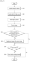
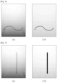
- FIG. 5 is a control flowchart according to an embodiment. Further, FIG. 6 is a view comparing images of a sensor and a camera captured a wire. A process in which the robot cleaner recognizes an obstacle such as a wire in an embodiment will be described with reference to FIGS. 5 and 6 .
- the camera 1406 may acquire the image of the region around the robot cleaner (S10).
- the camera 1406 may provide an image of the robot cleaner viewed from the front.
- the light source 1402 irradiates the light toward a location the same as a location captured by the camera 1406 (S20).
- a plurality of the light sources 1402 may be arranged and the plurality of light sources may irradiate light with a time difference.
- the light irradiated from the light source 1402 is received by the sensor 1404 after being reflected from the object (S30).
- information received from the sensor 1404 is processed to contain a distance value of an individual location through the controller 1800 (S40). That is, the information acquired from the sensor 1404 is information illustrating a two-dimensional plane.
- the controller 1800 may calculate the distance value by calculating an arrival time point of the light received by the sensor 1404, and the like, and allow the information received from the sensor 1404 to contain the distance value of the corresponding location. In one example, the controller 1800 may calculate the distance value of each location of the image in various forms other than the above-described scheme.
- the controller 1800 determines whether there is a singularity at which distance values calculated in adjacent portions are discontinuous in the corresponding image (S50).
- the adjacent portions may usually mean portions that are arranged close to each other enough for the distance values to form a single object. That is, when the image captured by the sensor 1404 is an image captured from a long distance, a distance between the adjacent portions may be set relatively small. On the other hand, when the captured image is an image captured at a close distance, the distance between the adjacent portions may be set relatively large.
- whether there are a plurality of singularities instead of one singularity may also be detected. This is because it may be suspected that a plurality of obstacles are arranged fairly close to each other when there is one singularity, but it may be expected that there is noise or an error in the image acquired by processing the information captured by the sensor 1404 when there are the plurality of singularities.
- the image acquired by processing the information acquired by the sensor 1404 may be a screen shown in (a) in FIG. 6 .
- a plurality of singularities are found in patches in the wire.
- the image acquired by processing the information acquired by the sensor 1404 may be ignored as information resulted from the error and it may be determined that there is no actual obstacle.
- the image acquired by processing the information acquired by the sensor 1404 is supplemented using an image captured by the camera as shown (b) in FIG. 6 (S60).
- the camera 1406 may capture the 2-dimensional image. That is, information of capturing a status of the location acquired by the sensor 1404 may be acquired.
- disconnected portions having the singularities interposed therebetween may be connected to each other and be determined as the same object. That is, even though the information in which there are the disconnected portions having the singularities interposed therebetween as shown in (a) in FIG. 6 is transmitted, when it is determined that two disconnected portions and a singularity interposed therebetween are in the same color, the disconnected portions may be supplemented as a single object as shown in (b) in FIG. 6 .
- the RGB camera acquires information about a color of the object from the camera. An error in which, even though the disconnected portions are the single object in the same color, the disconnected portions are determined as a plurality of objects by the sensor 1404 or are not determined as the object may be prevented.
- the disconnected portions having the singularities interposed therebetween may be connected to each other and be determined as the same object. That is, even though the information in which there are the disconnected portions having the singularities interposed therebetween as shown in (a) in FIG. 6 is transmitted, when it is determined that the two disconnected portions and the singularity interposed therebetween have the same brightness, the disconnected portions may be supplemented as a single object as shown in (b) in FIG. 6 .
- the IR camera acquires information about a shape of the object. In this connection, an error in which, even though the disconnected portions may be the single object based on the information acquired from the IR camera, the disconnected portions are determined as a plurality of objects by the sensor 1404 or are not determined as the object may be prevented.
- information about the obstacle and the like is determined based on the information acquired from the sensor 1404.
- the determination of the obstacle may be supplemented by the camera 1406 that acquires the two-dimensional information.
- the determination of the obstacle is supplemented by the information acquired by the camera 1406, whether the corresponding object is the obstacle is determined (S70).
- the plurality of singularities may also exist identically or there is no object in the corresponding portion. Therefore, even when the information acquired by the camera 1406 is considered, it may be concluded that there are two cases: the case in which the obstacle exists and the case in which the obstacle does not exist.
- the controller 1800 may use the machine learning technology to determine whether the corresponding obstacle should be avoided or whether the corresponding obstacle is able to be simply passed.
- the driver 1300 may be driven such that the robot cleaner travels while avoiding the obstacle so as not to collide with the obstacle.
- a travel direction of the robot cleaner may be set such that the robot cleaner passes the object.
- FIG. 7 is a view comparing images of a sensor and a camera captured a rod.
- the robot cleaner may accurately determine whether there is an object, such as a rod, having a small thickness compared to a length thereof in FIG. 7 .
- FIG. 7 is a screen in which information acquired by the sensor 1404 is image-processed by the controller 1800 to contain the distance value.
- (b) in FIG. 7 is a screen captured by the camera.
- the camera 1406 is the two-dimensional camera, which may include the RGB camera or the IR camera.
- the present embodiment provides a technology capable of improving a degree of recognition of the obstacle using the two-dimensional camera image in order to reduce the error of determining that the obstacle does not exist even though the obstacle exists.
Landscapes
- Engineering & Computer Science (AREA)
- Physics & Mathematics (AREA)
- Automation & Control Theory (AREA)
- Remote Sensing (AREA)
- Radar, Positioning & Navigation (AREA)
- General Physics & Mathematics (AREA)
- Aviation & Aerospace Engineering (AREA)
- Mechanical Engineering (AREA)
- Multimedia (AREA)
- Robotics (AREA)
- Electromagnetism (AREA)
- Computer Vision & Pattern Recognition (AREA)
- Signal Processing (AREA)
- Control Of Position, Course, Altitude, Or Attitude Of Moving Bodies (AREA)
- Electric Vacuum Cleaner (AREA)
Claims (15)
- Procédé pour commander un robot nettoyeur, le procédé comportant de :acquérir, par une caméra (1406), une image ;projeter, par une source lumineuse (1402), une lumière vers un emplacement identique à un emplacement où l'image acquise est capturée ;recevoir, par un capteur (1404), la lumière projetée à partir de la source lumineuse (1402) et réfléchie sur un objet ; ettraiter une image reçue du capteur (1404) pour contenir une valeur de distance d'un emplacement individuel ;caractérisé en ce que le procédé comporte en outre les étapes consistant à :
compléter l'image reçue du capteur (1404) avec l'image capturée par la caméra (1406) lorsqu'une singularité est trouvée, dans lequel des valeurs de distance calculées dans des parties adjacentes sont discontinues au niveau de la singularité. - Procédé selon la revendication 1, dans lequel la caméra (1406) capture une image bidimensionnelle.
- Procédé selon la revendication 2, dans lequel la caméra (1406) est une caméra RGB.
- Procédé selon la revendication 3, dans lequel le complément de l'image reçue du capteur (1404) avec l'image capturée par la caméra (1406) inclut l'étape consistant à :
joindre les unes aux autres des parties disjointes ayant la singularité intercalée entre celles-ci et déterminer les parties disjointes comme étant le même objet lorsque les parties disjointes sont de la même couleur. - Procédé selon la revendication 2, dans lequel la caméra (1406) est une caméra IR.
- Procédé selon la revendication 3, dans lequel le complément de l'image reçue du capteur (1404) avec l'image capturée par la caméra (1406) inclut l'étape consistant à :
joindre les unes aux autres des parties disjointes ayant la singularité intercalée entre celles-ci et déterminer les parties disjointes comme étant le même objet lorsque les parties disjointes ont la luminosité. - Procédé selon la revendication 1, dans lequel le complément de l'image reçue du capteur (1404) avec l'image capturée par la caméra (1406) inclut l'étape consistant à :
déterminer qu'il y a un obstacle sur une partie où la singularité existe lorsque des parties disjointes ayant la singularité intercalée entre celles-ci sont jointes les unes aux autres. - Procédé selon la revendication 7, dans lequel le robot nettoyeur se déplace tout en évitant l'obstacle.
- Robot nettoyeur comportant :une caméra (1406) pour acquérir une image ;une source lumineuse (1402) pour projeter de la lumière vers un emplacement identique à un emplacement où l'image acquise est capturée ;un capteur (1404) pour détecter que la lumière projetée à partir de la source lumineuse (1402) est réfléchie ; etune commande (1800) configurée pour traiter une image en utilisant la lumière détectée par le capteur (1404) pour calculer une valeur de distance d'un emplacement individuel dans l'image correspondante,caractérisé en ce que :
l'image est complétée avec l'image acquise par la caméra (1406) lorsqu'une singularité est trouvée, dans lequel des valeurs de distance calculées dans des parties adjacentes sont discontinues au niveau de la singularité. - Robot nettoyeur selon la revendication 9, dans lequel la caméra (1406) capture une image bidimensionnelle.
- Robot nettoyeur selon la revendication 10, dans lequel la caméra (1406) est une caméra RGB.
- Robot nettoyeur selon la revendication 11, dans lequel la commande (1800) est configurée pour joindre les unes aux autres des parties disjointes ayant la singularité intercalée entre celles-ci et déterminer les parties disjointes comme étant le même objet lorsque les parties disjointes sont de la même couleur.
- Robot nettoyeur selon la revendication 9, dans lequel la caméra (1406) est une caméra IR.
- Robot nettoyeur selon la revendication 12, dans lequel la commande (1800) est configurée pour joindre les unes aux autres des parties disjointes ayant la singularité intercalée entre celles-ci et déterminer les parties disjointes comme étant le même objet lorsque les parties disjointes ont la luminosité.
- Robot nettoyeur selon la revendication 9, dans lequel la commande (1800) est configurée pour déterminer qu'il y a un obstacle sur une partie où la singularité existe lorsque l'image est complétée de telle sorte que des parties déconnectées ayant la singularité interposée entre celles-ci sont jointes les unes aux autres.
Applications Claiming Priority (2)
| Application Number | Priority Date | Filing Date | Title |
|---|---|---|---|
| KR1020200029502A KR102348963B1 (ko) | 2020-03-10 | 2020-03-10 | 로봇 청소기 및 그 제어 방법 |
| PCT/KR2020/011686 WO2021182694A1 (fr) | 2020-03-10 | 2020-09-01 | Robot nettoyeur et son procédé de commande |
Publications (3)
| Publication Number | Publication Date |
|---|---|
| EP4117497A1 EP4117497A1 (fr) | 2023-01-18 |
| EP4117497A4 EP4117497A4 (fr) | 2024-08-21 |
| EP4117497B1 true EP4117497B1 (fr) | 2025-05-14 |
Family
ID=77672405
Family Applications (1)
| Application Number | Title | Priority Date | Filing Date |
|---|---|---|---|
| EP20924565.3A Active EP4117497B1 (fr) | 2020-03-10 | 2020-09-01 | Robot nettoyeur et son procédé de commande |
Country Status (4)
| Country | Link |
|---|---|
| US (1) | US12426755B2 (fr) |
| EP (1) | EP4117497B1 (fr) |
| KR (1) | KR102348963B1 (fr) |
| WO (1) | WO2021182694A1 (fr) |
Families Citing this family (2)
| Publication number | Priority date | Publication date | Assignee | Title |
|---|---|---|---|---|
| KR102590277B1 (ko) | 2021-11-17 | 2023-10-16 | 공주대학교 산학협력단 | 청소 위치 파악 장치 |
| KR20230154700A (ko) * | 2022-05-02 | 2023-11-09 | 삼성전자주식회사 | 사물까지의 거리를 산출하는 로봇 및 방법 |
Citations (1)
| Publication number | Priority date | Publication date | Assignee | Title |
|---|---|---|---|---|
| EP3782524A1 (fr) * | 2019-08-23 | 2021-02-24 | LG Electronics Inc. | Robot nettoyeur permettant d'éviter les situations de blocage grâce à l'intelligence artificielle et son procédé de fonctionnement |
Family Cites Families (13)
| Publication number | Priority date | Publication date | Assignee | Title |
|---|---|---|---|---|
| KR101417315B1 (ko) | 2012-08-13 | 2014-07-10 | 서울과학기술대학교 산학협력단 | 로봇 청소기 |
| KR20140119325A (ko) * | 2013-03-28 | 2014-10-10 | 인텔렉추얼디스커버리 주식회사 | 깊이 이미지의 노이즈를 보완하는 장치 및 방법 |
| KR101620428B1 (ko) * | 2014-10-10 | 2016-05-12 | 엘지전자 주식회사 | 로봇 청소기 및 로봇 청소기의 제어방법 |
| KR102398330B1 (ko) | 2015-06-12 | 2022-05-16 | 엘지전자 주식회사 | 이동 로봇 및 그 제어방법 |
| KR101897775B1 (ko) * | 2016-03-04 | 2018-09-12 | 엘지전자 주식회사 | 이동 로봇 및 그 제어방법 |
| US20170329347A1 (en) * | 2016-05-11 | 2017-11-16 | Brain Corporation | Systems and methods for training a robot to autonomously travel a route |
| JP6827758B2 (ja) | 2016-10-12 | 2021-02-10 | 東芝映像ソリューション株式会社 | 移動式アシスト装置及び移動式アシスト方法 |
| KR102461938B1 (ko) * | 2017-04-04 | 2022-10-31 | 엘지전자 주식회사 | 주행 지면의 장애물을 식별하는 방법 및 이를 구현하는 로봇 |
| KR20190040746A (ko) | 2017-10-11 | 2019-04-19 | 주식회사 대진애니메이션 | 3차원 관심영역 복원 시스템 및 방법 |
| JP7075201B2 (ja) * | 2017-12-15 | 2022-05-25 | 東芝ライフスタイル株式会社 | 電気掃除機 |
| US10513037B2 (en) * | 2017-12-15 | 2019-12-24 | Ankobot (Shanghai) Smart Technologies Co., Ltd. | Control method and system, and mobile robot using the same |
| JP7149502B2 (ja) | 2018-03-29 | 2022-10-07 | パナソニックIpマネジメント株式会社 | 自律移動掃除機、自律移動掃除機による掃除方法、及び自律移動掃除機用プログラム |
| CN111028350B (zh) * | 2019-11-21 | 2022-05-20 | 大连理工大学 | 一种利用双目立体相机构建栅格地图的方法 |
-
2020
- 2020-03-10 KR KR1020200029502A patent/KR102348963B1/ko active Active
- 2020-09-01 US US17/798,349 patent/US12426755B2/en active Active
- 2020-09-01 WO PCT/KR2020/011686 patent/WO2021182694A1/fr not_active Ceased
- 2020-09-01 EP EP20924565.3A patent/EP4117497B1/fr active Active
Patent Citations (1)
| Publication number | Priority date | Publication date | Assignee | Title |
|---|---|---|---|---|
| EP3782524A1 (fr) * | 2019-08-23 | 2021-02-24 | LG Electronics Inc. | Robot nettoyeur permettant d'éviter les situations de blocage grâce à l'intelligence artificielle et son procédé de fonctionnement |
Also Published As
| Publication number | Publication date |
|---|---|
| EP4117497A1 (fr) | 2023-01-18 |
| WO2021182694A1 (fr) | 2021-09-16 |
| KR102348963B1 (ko) | 2022-01-11 |
| EP4117497A4 (fr) | 2024-08-21 |
| KR20210122921A (ko) | 2021-10-13 |
| US20230104931A1 (en) | 2023-04-06 |
| US12426755B2 (en) | 2025-09-30 |
Similar Documents
| Publication | Publication Date | Title |
|---|---|---|
| EP3813623B1 (fr) | Pluralité d'appareils de nettoyage autonomes et procédé de commande de tels appareils de nettoyage autonomes | |
| KR102048992B1 (ko) | 인공지능 청소기 및 그 제어방법 | |
| AU2020208074B2 (en) | Mobile robot and method of controlling mobile robot | |
| EP3996565B1 (fr) | Dispositif d'accueil et système de robot mobile | |
| AU2020362530B2 (en) | Robot cleaner and method for controlling the same | |
| EP4505927A1 (fr) | Dispositifs de nettoyage automatique, procédé de commande et support de stockage | |
| KR20210108771A (ko) | 이동 로봇 및 복수의 이동 로봇의 제어방법 | |
| AU2020231781B2 (en) | Moving robot and controlling method for the moving robot | |
| KR20200087301A (ko) | 이동 로봇 | |
| KR20200119375A (ko) | 이동 로봇 및 이동 로봇의 제어방법 | |
| EP4117497B1 (fr) | Robot nettoyeur et son procédé de commande | |
| KR102081340B1 (ko) | 복수의 로봇 청소기 및 그 제어방법 | |
| EP4116044B1 (fr) | Robot mobile et son procédé de commande | |
| EP4117496B1 (fr) | Robot nettoyeur et procédé pour le commander | |
| KR20200133544A (ko) | 이동 로봇 및 그 제어방법 | |
| KR102398332B1 (ko) | 청소기 및 그 제어방법 | |
| KR20220121483A (ko) | 지능적 맵 생성 방법 및 그 이동 로봇 |
Legal Events
| Date | Code | Title | Description |
|---|---|---|---|
| STAA | Information on the status of an ep patent application or granted ep patent |
Free format text: STATUS: THE INTERNATIONAL PUBLICATION HAS BEEN MADE |
|
| PUAI | Public reference made under article 153(3) epc to a published international application that has entered the european phase |
Free format text: ORIGINAL CODE: 0009012 |
|
| STAA | Information on the status of an ep patent application or granted ep patent |
Free format text: STATUS: REQUEST FOR EXAMINATION WAS MADE |
|
| 17P | Request for examination filed |
Effective date: 20220915 |
|
| AK | Designated contracting states |
Kind code of ref document: A1 Designated state(s): AL AT BE BG CH CY CZ DE DK EE ES FI FR GB GR HR HU IE IS IT LI LT LU LV MC MK MT NL NO PL PT RO RS SE SI SK SM TR |
|
| DAV | Request for validation of the european patent (deleted) | ||
| DAX | Request for extension of the european patent (deleted) | ||
| A4 | Supplementary search report drawn up and despatched |
Effective date: 20240724 |
|
| RIC1 | Information provided on ipc code assigned before grant |
Ipc: A47L 9/28 20060101AFI20240718BHEP |
|
| GRAP | Despatch of communication of intention to grant a patent |
Free format text: ORIGINAL CODE: EPIDOSNIGR1 |
|
| STAA | Information on the status of an ep patent application or granted ep patent |
Free format text: STATUS: GRANT OF PATENT IS INTENDED |
|
| INTG | Intention to grant announced |
Effective date: 20241220 |
|
| GRAS | Grant fee paid |
Free format text: ORIGINAL CODE: EPIDOSNIGR3 |
|
| GRAA | (expected) grant |
Free format text: ORIGINAL CODE: 0009210 |
|
| STAA | Information on the status of an ep patent application or granted ep patent |
Free format text: STATUS: THE PATENT HAS BEEN GRANTED |
|
| AK | Designated contracting states |
Kind code of ref document: B1 Designated state(s): AL AT BE BG CH CY CZ DE DK EE ES FI FR GB GR HR HU IE IS IT LI LT LU LV MC MK MT NL NO PL PT RO RS SE SI SK SM TR |
|
| REG | Reference to a national code |
Ref country code: GB Ref legal event code: FG4D |
|
| REG | Reference to a national code |
Ref country code: CH Ref legal event code: EP |
|
| REG | Reference to a national code |
Ref country code: IE Ref legal event code: FG4D |
|
| REG | Reference to a national code |
Ref country code: DE Ref legal event code: R096 Ref document number: 602020051445 Country of ref document: DE |
|
| REG | Reference to a national code |
Ref country code: NL Ref legal event code: MP Effective date: 20250514 |
|
| PG25 | Lapsed in a contracting state [announced via postgrant information from national office to epo] |
Ref country code: FI Free format text: LAPSE BECAUSE OF FAILURE TO SUBMIT A TRANSLATION OF THE DESCRIPTION OR TO PAY THE FEE WITHIN THE PRESCRIBED TIME-LIMIT Effective date: 20250514 Ref country code: PT Free format text: LAPSE BECAUSE OF FAILURE TO SUBMIT A TRANSLATION OF THE DESCRIPTION OR TO PAY THE FEE WITHIN THE PRESCRIBED TIME-LIMIT Effective date: 20250915 Ref country code: ES Free format text: LAPSE BECAUSE OF FAILURE TO SUBMIT A TRANSLATION OF THE DESCRIPTION OR TO PAY THE FEE WITHIN THE PRESCRIBED TIME-LIMIT Effective date: 20250514 |
|
| REG | Reference to a national code |
Ref country code: LT Ref legal event code: MG9D |
|
| PG25 | Lapsed in a contracting state [announced via postgrant information from national office to epo] |
Ref country code: NO Free format text: LAPSE BECAUSE OF FAILURE TO SUBMIT A TRANSLATION OF THE DESCRIPTION OR TO PAY THE FEE WITHIN THE PRESCRIBED TIME-LIMIT Effective date: 20250814 Ref country code: GR Free format text: LAPSE BECAUSE OF FAILURE TO SUBMIT A TRANSLATION OF THE DESCRIPTION OR TO PAY THE FEE WITHIN THE PRESCRIBED TIME-LIMIT Effective date: 20250815 |
|
| PG25 | Lapsed in a contracting state [announced via postgrant information from national office to epo] |
Ref country code: PL Free format text: LAPSE BECAUSE OF FAILURE TO SUBMIT A TRANSLATION OF THE DESCRIPTION OR TO PAY THE FEE WITHIN THE PRESCRIBED TIME-LIMIT Effective date: 20250514 Ref country code: NL Free format text: LAPSE BECAUSE OF FAILURE TO SUBMIT A TRANSLATION OF THE DESCRIPTION OR TO PAY THE FEE WITHIN THE PRESCRIBED TIME-LIMIT Effective date: 20250514 |
|
| REG | Reference to a national code |
Ref country code: AT Ref legal event code: MK05 Ref document number: 1794078 Country of ref document: AT Kind code of ref document: T Effective date: 20250514 |
|
| PG25 | Lapsed in a contracting state [announced via postgrant information from national office to epo] |
Ref country code: BG Free format text: LAPSE BECAUSE OF FAILURE TO SUBMIT A TRANSLATION OF THE DESCRIPTION OR TO PAY THE FEE WITHIN THE PRESCRIBED TIME-LIMIT Effective date: 20250514 |
|
| PG25 | Lapsed in a contracting state [announced via postgrant information from national office to epo] |
Ref country code: HR Free format text: LAPSE BECAUSE OF FAILURE TO SUBMIT A TRANSLATION OF THE DESCRIPTION OR TO PAY THE FEE WITHIN THE PRESCRIBED TIME-LIMIT Effective date: 20250514 |
|
| PG25 | Lapsed in a contracting state [announced via postgrant information from national office to epo] |
Ref country code: AT Free format text: LAPSE BECAUSE OF FAILURE TO SUBMIT A TRANSLATION OF THE DESCRIPTION OR TO PAY THE FEE WITHIN THE PRESCRIBED TIME-LIMIT Effective date: 20250514 |
|
| PG25 | Lapsed in a contracting state [announced via postgrant information from national office to epo] |
Ref country code: RS Free format text: LAPSE BECAUSE OF FAILURE TO SUBMIT A TRANSLATION OF THE DESCRIPTION OR TO PAY THE FEE WITHIN THE PRESCRIBED TIME-LIMIT Effective date: 20250814 |
|
| PG25 | Lapsed in a contracting state [announced via postgrant information from national office to epo] |
Ref country code: IS Free format text: LAPSE BECAUSE OF FAILURE TO SUBMIT A TRANSLATION OF THE DESCRIPTION OR TO PAY THE FEE WITHIN THE PRESCRIBED TIME-LIMIT Effective date: 20250914 |
|
| PG25 | Lapsed in a contracting state [announced via postgrant information from national office to epo] |
Ref country code: LV Free format text: LAPSE BECAUSE OF FAILURE TO SUBMIT A TRANSLATION OF THE DESCRIPTION OR TO PAY THE FEE WITHIN THE PRESCRIBED TIME-LIMIT Effective date: 20250514 |
|
| PG25 | Lapsed in a contracting state [announced via postgrant information from national office to epo] |
Ref country code: DK Free format text: LAPSE BECAUSE OF FAILURE TO SUBMIT A TRANSLATION OF THE DESCRIPTION OR TO PAY THE FEE WITHIN THE PRESCRIBED TIME-LIMIT Effective date: 20250514 Ref country code: SM Free format text: LAPSE BECAUSE OF FAILURE TO SUBMIT A TRANSLATION OF THE DESCRIPTION OR TO PAY THE FEE WITHIN THE PRESCRIBED TIME-LIMIT Effective date: 20250514 |
|
| PG25 | Lapsed in a contracting state [announced via postgrant information from national office to epo] |
Ref country code: CZ Free format text: LAPSE BECAUSE OF FAILURE TO SUBMIT A TRANSLATION OF THE DESCRIPTION OR TO PAY THE FEE WITHIN THE PRESCRIBED TIME-LIMIT Effective date: 20250514 |
|
| PG25 | Lapsed in a contracting state [announced via postgrant information from national office to epo] |
Ref country code: EE Free format text: LAPSE BECAUSE OF FAILURE TO SUBMIT A TRANSLATION OF THE DESCRIPTION OR TO PAY THE FEE WITHIN THE PRESCRIBED TIME-LIMIT Effective date: 20250514 |
|
| PG25 | Lapsed in a contracting state [announced via postgrant information from national office to epo] |
Ref country code: SK Free format text: LAPSE BECAUSE OF FAILURE TO SUBMIT A TRANSLATION OF THE DESCRIPTION OR TO PAY THE FEE WITHIN THE PRESCRIBED TIME-LIMIT Effective date: 20250514 |
|
| PG25 | Lapsed in a contracting state [announced via postgrant information from national office to epo] |
Ref country code: IT Free format text: LAPSE BECAUSE OF FAILURE TO SUBMIT A TRANSLATION OF THE DESCRIPTION OR TO PAY THE FEE WITHIN THE PRESCRIBED TIME-LIMIT Effective date: 20250514 |
|
| PG25 | Lapsed in a contracting state [announced via postgrant information from national office to epo] |
Ref country code: RO Free format text: LAPSE BECAUSE OF FAILURE TO SUBMIT A TRANSLATION OF THE DESCRIPTION OR TO PAY THE FEE WITHIN THE PRESCRIBED TIME-LIMIT Effective date: 20250514 |
|
| REG | Reference to a national code |
Ref country code: DE Ref legal event code: R097 Ref document number: 602020051445 Country of ref document: DE |
|
| PLBE | No opposition filed within time limit |
Free format text: ORIGINAL CODE: 0009261 |
|
| STAA | Information on the status of an ep patent application or granted ep patent |
Free format text: STATUS: NO OPPOSITION FILED WITHIN TIME LIMIT |
|
| REG | Reference to a national code |
Ref country code: CH Ref legal event code: L10 Free format text: ST27 STATUS EVENT CODE: U-0-0-L10-L00 (AS PROVIDED BY THE NATIONAL OFFICE) Effective date: 20260325 |
|
| 26N | No opposition filed |
Effective date: 20260217 |
|
| REG | Reference to a national code |
Ref country code: CH Ref legal event code: H13 Free format text: ST27 STATUS EVENT CODE: U-0-0-H10-H13 (AS PROVIDED BY THE NATIONAL OFFICE) Effective date: 20260425 |