EP4118375B1 - Procédé et dispositif de surveillance d'un point d'accès débouchant dans une zone de sécurité d'une enrouleuse ou d'une dérouleuse à rouleaux, et machine d'impression - Google Patents
Procédé et dispositif de surveillance d'un point d'accès débouchant dans une zone de sécurité d'une enrouleuse ou d'une dérouleuse à rouleaux, et machine d'impression Download PDFInfo
- Publication number
- EP4118375B1 EP4118375B1 EP21715800.5A EP21715800A EP4118375B1 EP 4118375 B1 EP4118375 B1 EP 4118375B1 EP 21715800 A EP21715800 A EP 21715800A EP 4118375 B1 EP4118375 B1 EP 4118375B1
- Authority
- EP
- European Patent Office
- Prior art keywords
- protection
- fields
- monitoring
- breach
- field
- Prior art date
- Legal status (The legal status is an assumption and is not a legal conclusion. Google has not performed a legal analysis and makes no representation as to the accuracy of the status listed.)
- Active
Links
Images



Classifications
-
- B—PERFORMING OPERATIONS; TRANSPORTING
- B41—PRINTING; LINING MACHINES; TYPEWRITERS; STAMPS
- B41F—PRINTING MACHINES OR PRESSES
- B41F33/00—Indicating, counting, warning, control or safety devices
- B41F33/0018—Protection means against injury to the operator
-
- F—MECHANICAL ENGINEERING; LIGHTING; HEATING; WEAPONS; BLASTING
- F16—ENGINEERING ELEMENTS AND UNITS; GENERAL MEASURES FOR PRODUCING AND MAINTAINING EFFECTIVE FUNCTIONING OF MACHINES OR INSTALLATIONS; THERMAL INSULATION IN GENERAL
- F16P—SAFETY DEVICES IN GENERAL; SAFETY DEVICES FOR PRESSES
- F16P3/00—Safety devices acting in conjunction with the control or operation of a machine; Control arrangements requiring the simultaneous use of two or more parts of the body
- F16P3/12—Safety devices acting in conjunction with the control or operation of a machine; Control arrangements requiring the simultaneous use of two or more parts of the body with means, e.g. feelers, which in case of the presence of a body part of a person in or near the danger zone influence the control or operation of the machine
- F16P3/14—Safety devices acting in conjunction with the control or operation of a machine; Control arrangements requiring the simultaneous use of two or more parts of the body with means, e.g. feelers, which in case of the presence of a body part of a person in or near the danger zone influence the control or operation of the machine the means being photocells or other devices sensitive without mechanical contact
- F16P3/144—Safety devices acting in conjunction with the control or operation of a machine; Control arrangements requiring the simultaneous use of two or more parts of the body with means, e.g. feelers, which in case of the presence of a body part of a person in or near the danger zone influence the control or operation of the machine the means being photocells or other devices sensitive without mechanical contact using light grids
-
- B—PERFORMING OPERATIONS; TRANSPORTING
- B41—PRINTING; LINING MACHINES; TYPEWRITERS; STAMPS
- B41J—TYPEWRITERS; SELECTIVE PRINTING MECHANISMS, i.e. MECHANISMS PRINTING OTHERWISE THAN FROM A FORME; CORRECTION OF TYPOGRAPHICAL ERRORS
- B41J15/00—Devices or arrangements of selective printing mechanisms, e.g. ink-jet printers or thermal printers, specially adapted for supporting or handling copy material in continuous form, e.g. webs
- B41J15/04—Supporting, feeding, or guiding devices; Mountings for web rolls or spindles
- B41J15/042—Supporting, feeding, or guiding devices; Mountings for web rolls or spindles for loading rolled-up continuous copy material into printers, e.g. for replacing a used-up paper roll; Point-of-sale printers with openable casings allowing access to the rolled-up continuous copy material
-
- B—PERFORMING OPERATIONS; TRANSPORTING
- B65—CONVEYING; PACKING; STORING; HANDLING THIN OR FILAMENTARY MATERIAL
- B65H—HANDLING THIN OR FILAMENTARY MATERIAL, e.g. SHEETS, WEBS, CABLES
- B65H19/00—Changing the web roll
- B65H19/10—Changing the web roll in unwinding mechanisms or in connection with unwinding operations
- B65H19/12—Lifting, transporting, or inserting the web roll; Removing empty core
-
- B—PERFORMING OPERATIONS; TRANSPORTING
- B65—CONVEYING; PACKING; STORING; HANDLING THIN OR FILAMENTARY MATERIAL
- B65H—HANDLING THIN OR FILAMENTARY MATERIAL, e.g. SHEETS, WEBS, CABLES
- B65H19/00—Changing the web roll
- B65H19/22—Changing the web roll in winding mechanisms or in connection with winding operations
- B65H19/30—Lifting, transporting, or removing the web roll; Inserting core
-
- B—PERFORMING OPERATIONS; TRANSPORTING
- B65—CONVEYING; PACKING; STORING; HANDLING THIN OR FILAMENTARY MATERIAL
- B65H—HANDLING THIN OR FILAMENTARY MATERIAL, e.g. SHEETS, WEBS, CABLES
- B65H26/00—Warning or safety devices, e.g. automatic fault detectors, stop-motions, for web-advancing mechanisms
- B65H26/08—Warning or safety devices, e.g. automatic fault detectors, stop-motions, for web-advancing mechanisms responsive to a predetermined diameter
-
- B—PERFORMING OPERATIONS; TRANSPORTING
- B65—CONVEYING; PACKING; STORING; HANDLING THIN OR FILAMENTARY MATERIAL
- B65H—HANDLING THIN OR FILAMENTARY MATERIAL, e.g. SHEETS, WEBS, CABLES
- B65H2553/00—Sensing or detecting means
- B65H2553/40—Sensing or detecting means using optical, e.g. photographic, elements
- B65H2553/41—Photoelectric detectors
- B65H2553/416—Array arrangement, i.e. row of emitters or detectors
-
- B—PERFORMING OPERATIONS; TRANSPORTING
- B65—CONVEYING; PACKING; STORING; HANDLING THIN OR FILAMENTARY MATERIAL
- B65H—HANDLING THIN OR FILAMENTARY MATERIAL, e.g. SHEETS, WEBS, CABLES
- B65H2557/00—Means for control not provided for in groups B65H2551/00 - B65H2555/00
- B65H2557/20—Calculating means; Controlling methods
Definitions
- the invention relates to a method and a device for monitoring an access leading into a safety area of a roll unwinder or rewinder, as well as to a printing machine with such a device according to the preamble of claims 1, 8 and 14 respectively.
- a web printing machine with a roll unwinder and a roll rewinder is known, wherein access to a safety area of the roll rewinder is provided by a monitoring sensor system in the form of a multi-beam, e.g. two-beam, light barrier system with muting function.
- a monitoring sensor system in the form of a multi-beam, e.g. two-beam, light barrier system with muting function.
- the EN 10 2010 031 650 A1 relates to a roll changer with a safety area, whereby access to a safety area is monitored by a light grid with a large number of light barriers.
- the EP 3 415 804 A1 relates to a safety device for securing a passage, whereby access is checked for a permitted object by a scanner, e.g. in the middle above the passage, and if such an object is present, so-called muting takes place, ie bridging the safety function.
- a scanner e.g. in the middle above the passage
- muting takes place, ie bridging the safety function.
- the passage is monitored by two scanners arranged in the respective upper corners. The two scanners observe two protective fields that complement each other to form the entire monitoring area.
- the EN 10 2019 116 806 A1 relates to a device and method for monitoring a danger area, wherein a first laser is provided for monitoring a plane parallel to the opening and a second laser is provided for monitoring a second plane.
- An access security system is disclosed, wherein the access level is monitored by a first sensor and an approaching object is detected in its contour by a second sensor.
- the EP 3 339 715 A1 relates to an access protection system, particularly for protecting personnel from robots and machines in automatic manufacturing and packaging processes.
- the access protection system comprises two laser scanners that monitor adjacent or overlapping safety protection fields as well as two or more detection protection fields on each side.
- the detection protection fields are intended to detect objects defined as permitted for passage in order to deactivate the safety field in an area corresponding to the known object.
- the left and right detection protection fields are aimed at prominent locations for the permitted objects.
- the invention is based on the object of creating a method and a device for monitoring an access leading into a safety area of a roll unwinder or rewinder, as well as a printing machine with such a device.
- the advantages that can be achieved with the invention are in particular that the solution can be easily adapted to applications with different roll size and/or roll type spectra, e.g. without having to change the scope of the sensors.
- applications can also be implemented whose usable roll spectrum ranges from e.g. 200 mm roll diameter to 1,800 mm roll diameter and/or have a stepped roll diameter that varies over the length.
- Such large and/or Stepped rolls are particularly important in packaging printing and/or in industrial printing with a printing machine comprising a printing unit which works according to a formless printing process, e.g. inkjet printing.
- an access leading into a safety area of a roll unwinder or winder, through which material rolls can be transported in and/or out, is scanned, the access being formed by an opening provided between two elements that mechanically delimit the safety area, and the access being monitored by a monitoring sensor system.
- Two scanners included in the monitoring sensor system each scan an angular area lying in the same plane running in the opening with their respective measuring beams.
- the access is monitored in a pattern of protective fields with several protective fields of different sizes and/or shapes, the scan images of the two scanners in different, adjacent or overlapping sub-areas of the plane being checked for a - in particular simultaneous - protective field violation of the relevant protective fields of different sizes and/or shapes, and information about the admissibility of a detected protective field violation is derived from an evaluation of the injury patterns of violated protective fields obtained in the two sub-areas.
- the above-mentioned protective fields of different sizes and/or shapes overlap, for example, at least in part of their area, or at least one or more of the protective fields of different sizes and/or shapes are even completely enclosed by a next larger and/or next wider protective field or at least in terms of width and/or upwards, preferably at least in terms of width and upwards.
- the scan images from the two scanners are checked for a violation of the protective field in the different - possibly overlapping - sub-areas of the respective same protective field.
- protective fields are preferably used that lie in the monitored plane E and extend on both sides in a mirror-symmetrical manner to a vertical line that is central to the transport path with respect to the horizontal extension in the plane.
- This vertical line V runs, for example, in the horizontal direction of the plane or the passage through the point in the plane through which a center point of the object to be transported, viewed in terms of width, e.g. halfway along the axis of symmetry of a roll to be transported or the center axis of a container to be transported running in the direction of transport, runs as planned during the passage of this object, e.g. roll or container.
- This is defined, for example, by the characteristics of a means of transport and its mechanically or otherwise predetermined route.
- access to a safety area is formed by an opening provided between two elements which mechanically delimit the safety area, wherein a monitoring sensor system is provided for monitoring the access, which comprises two scanners, the measuring beams of which each cover an angular range lying in the same opening.
- a pattern of protective fields with several protective fields of different sizes and/or shapes is provided, of which at least one or more is or are completely enclosed by a next larger and/or next wider protective field or at least in width and/or upwards, preferably at least in width and upwards, wherein evaluation means are included, by means of which the scan images of the two scanners for several of these protective fields of different sizes and/or shapes are displayed in different, adjacent or, if necessary, overlapping sub-areas of the plane are checked and/or can be checked for a protective field violation of the relevant protective fields of different size and/or shape.
- the evaluation center can therefore be used to check or evaluate the scan images of the two scanners in particular for a protective field violation in the different, i.e. deviating, sub-areas of the same protective field lying in the same plane - or in each case the same protective field.
- the protective fields are provided in such a way that they are defined as sub-areas in the plane to be monitored, for example by parameterization in a software included in the scanners or a data processing device connected to them. They are preferably changeable - for example via changeable parameters.
- monitoring cases are defined or can be defined in which different field sets, i.e. patterns of protective fields, are used for different operating situations, i.e. classes or types of passing objects.
- detection and, if necessary, switching takes place automatically according to predetermined rules.
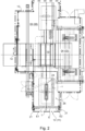
- a printing machine advantageously designed as a web-fed printing machine, comprises one or more printing units 01, by means of which a printing material 02, e.g. a printing material web 02, can be printed on the same or both sides one after the other, in particular using the inkjet process, a printing material template 03, e.g. an unwinder 03, for example a roll unwinder 03, in particular a roll changer 03, a downstream product holder 04, e.g. a winder 04, in particular a roll winder 04, and preferably a dryer 06 arranged downstream of the respective printing unit 01 in the printing material path.
- the printing unit 01 for multi-color printing comprises a plurality of printing devices 07 arranged one behind the other in the printing material transport direction, in particular inkjet print heads 07, each with one or more nozzles for the controlled release of the ink.
- a safety area 08; 09 extends, for example, over at least the width of the rewinder 04, which safety area is essentially completely delimited on the one hand by the unwinder 03 or rewinder 04 itself and by one or more connected units and/or mechanical shut-off devices 13 as well as by one or more sensor-monitored accesses 11; 12 in such a way that operational entry by operators and/or the supply or removal of rolls 16; 17 or sleeves can only be accessed via monitored access points 11; 12.
- the access point 11; 12 is formed by an opening provided between two elements delimiting the security area 08; 09.
- an access option e.g. a preferably sensor-monitored door 14, in particular a sliding door 14, can be provided, which enables the operating personnel - when a certain machine state exists - to enter the secured area, i.e. the safety area 08; 09.
- a sensor-monitored access 11; 12 is provided for the roll and/or core passage, preferably on a machine side facing the roll unwinder 03 or roll rewinder 04 and/or laterally aligned with a transfer station 19 in front of the roll unwinder 03 or roll rewinder 04.
- Such a safety area 09; 08 with sensor-monitored access 12; 11 is shown using the example of the roll winder 04, but is to be transferred accordingly to an embodiment of a safety area 08 provided instead or in addition to this on the roll unwinder 03.
- the reference numerals assigned to the roll unwinder 03 are included as brackets for this purpose.
- the solution according to the invention can also be applied, for example, to a roll unwinder 03 of a printing press in which an unwound printing material web 02 is cut into printing material sheets in front of the only or first printing unit 01, which are then printed.
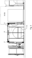
- the preferably "frontal" access 12 (11) for the passage of rollers 17 (16) and/or sleeves is preferably designed as an open passage 12 (11) for area protection with an optically effective monitoring sensor system that optically monitors the access 12 (11), in particular in the area of a preferably horizontal plane E located in the access 12 (11), e.g. monitoring plane E.
- the monitoring plane E is preferably perpendicular to a plane present when the roller 17 (16) and/or sleeve passes along a transport path.
- the transport path is preferably predetermined mechanically, for example by a guide device or by a guide 18 guiding a transport means 24, e.g. transport carriage 24, e.g. a chain guide sunk into the ground and used to propel the transport carriage, or at least in the case of a free, ie unguided, transport means 24 is marked optically or in some other way.
- the monitoring sensor system comprises two sensors 21 designed as scanners 21 and evaluation means 23 implemented in these and/or in a separate evaluation device, by means of which the scan result, i.e. the scan image recorded in each case, can be checked for stored and/or storeable criteria and/or patterns.
- the two scanners 21 are provided on both sides of the transport path, in particular on both sides of a vertical V lying in the monitoring plane E and intersecting the roll axis of the rolls 17 (16) transported on the intended transport path, on plane E. They are preferably arranged at the same height and/or above the top side of a transported roll 17 (16) of maximum diameter D max to be used, e.g. above 1,800 mm above the floor, and/or axially symmetrical to the said vertical V. They are mounted on, for example, a frame 26, e.g. B. a portal-like frame 26, arranged such that their measuring or scanning beam covers an angular range lying in the plane E and/or they each monitor an angular range lying in the plane E.
- the access 11; 12 is now monitored by the two scanners 21 in a pattern of protective fields M(Fj) with - ie, for example, at least comprehensively or possibly consisting of - several protective fields Fj of different sizes and/or shapes, whereby, however, for at least several of the protective fields Fj of different sizes and/or shapes, the scan images of the two scanners 21 in different, adjoining or overlapping partial areas E1; E2 of the plane E are checked for a - in particular simultaneous - protective field violation of the relevant protective fields Fj of different sizes and/or shapes are checked, and information on the admissibility of a detected protective field violation is derived from an evaluation of the injury patterns of violated protective fields Fj obtained in the two sub-areas.
- simultaneity can be understood, for example, in the sense that at least electrotechnical or evaluation-related running time differences and, if applicable, a relative entry tolerance, the limit of which, for example - possibly depending on the existing or system-related operating transport speed - is at a value of at most one second, preferably at most 100 milliseconds, are still considered to be simultaneous.
- a protective field violation in at least one of the protective fields Fj, in the two sub-areas E1; E2 only one or more identical protective fields Fj, i.e. one identical injury pattern or injury patterns that differ from one another by only a definable number of one or more next larger and/or wider protective fields Fj, i.e. on one side or in one sub-area E1; E2 one or possibly a defined number of - e.g. continuously or continuously increasing - next larger (i.e. in particular encompassing the relevant protective field Fj completely or at least in width and/or upwards) injured protective fields Fj than on the other side or the other sub-area E2; E1.
- the above tolerance limit is given with the number one, i.e. on one of the sides or in In one of the partial areas E1; E2, at most one protective field Fj+1 that is the next larger may be violated than on the other side or in the other partial area E2; E1.
- Protective fields Fj of adjacent field sizes are to be understood as two protective fields Fj; Fj+1, for example, of which the larger or at least wider protective field Fj in the set of the present protective fields Fj represents the next larger or next wider protective field Fj and - at least as far as the extension in the horizontal direction and/or upwards is concerned - comprises the smaller and/or narrower of the two protective fields Fj-1.
- the protective fields Fj to be considered preferably extend mirror-symmetrically to the above-mentioned vertical V in the plane E.
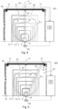
- the partial areas E1; E2 of the protective fields Fj to be evaluated by the two scanners 21 are shown in the illustrations Fig. 4 to Fig. 10 highlighted by two boundary lines of different thicknesses.
- the monitoring sensor system is preferably designed such that at least one drive means 28 driving the transport means 24, e.g. motor 28, stops and/or a warning signal is issued if, when the monitoring of the access 12 (11) is activated, and without muting caused by "permitted" roller transport, a protection area violation is detected, e.g. an operator passes through the area protection or monitored level E without permission.
- a protection area violation e.g. an operator passes through the area protection or monitored level E without permission.
- a switch can be made between a switching state of the monitoring sensors in which any protective field violation leads to safety measures and a switching state in which a symmetrical entry leads to the activation of the muting function for a corresponding protective field area and an asymmetrical violation leads to the activation of the safety measures, for example as a result of the approach of a roller 17 (16).
- the approach can be carried out, for example, by sensors 29 provided on the transport path, in particular above the transport path on both sides of the plane E, e.g. proximity sensors 29, in particular proximity switches 29. Once the second sensor 29 has also been passed through, a switch can be made from the switching state that tolerates the passage of the roller back to the switching state for monitoring any protective field violations.
- an intrusion detected via the images of the respective scanner 21 in the partial area E1; E2 to be evaluated for the relevant scanner 21 occurs simultaneously in only one or more of the same protective fields Fj, possibly taking into account a tolerance specified below, it is assumed that an object that is axially symmetrical with respect to the vertical V has entered, which can be, for example, a roll 17 (16) sitting on a transport device 24, with or without a so-called adapter 27, i.e. a likewise symmetrical attachment 27, on the transport carriage 24 for rolls 17 (16) of smaller diameter D.
- tolerance ranges are provided for the evaluation of the fault. This tolerance range is given, for example, by the fact that a deviation in the violation between the two partial areas E1; E2 is only tolerated by a definable small number of levels, preferably by just one level, i.e. in one partial area E1; E2 an additional violation of the next largest protective field Fj in comparison to the other partial area E2; E1. In an embodiment that is advantageous in terms of safety, however, this does not apply to entry into the area adjoining the boundaries of the passage, for example the rack 26 or a frame 26, to the inside up to the next smallest of the defined or definable protective fields Fj.
- the triggering of safety measures is suppressed for the area of the affected protective fields Fj or for the smallest affected protective field Fj that includes the other simultaneously violated protective fields Fj, i.e. a so-called muting function is activated, while for the part of the level E monitored by the two scanners 21 lying outside of this, monitoring is maintained, in particular for an asymmetrical entry of an object into the sub-areas E1; E2, with safety measures to be triggered accordingly in the event of a violation, i.e. asymmetrical entry, e.g. an acoustic and/or optical warning and/or stopping or blocking of the roller transport.
- a so-called muting function is activated, while for the part of the level E monitored by the two scanners 21 lying outside of this, monitoring is maintained, in particular for an asymmetrical entry of an object into the sub-areas E1; E2, with safety measures to be triggered accordingly in the event of a violation, i.e. asymmetrical entry, e.g
- a so-called symmetrical field set is used for the evaluation of the protective fields Fj provided here, which are formed symmetrically to the vertical (see e.g. Fig.4 or Fig.6 ).
- this symmetrical measurement field evaluation can be problematic if an object or living being resting on top of the roller 17 (16), possibly within the scope of existing tolerances, simultaneously enters, for example, a larger protective field Fj+1; Fj+2, possibly taking the above-mentioned tolerances into account. In this case, it could be incorrectly concluded that there is a change in diameter of a stepped roller 17 (16), i.e. a roller 17 (16) with sections of different diameters D. It may then not be possible to distinguish between the presence of a stepped roller 17 (16) and an impermissible penetration of an approximately symmetrical object or living being on the roller 17 (16).
- the partial areas E1; E2 of the images provided by the two scanners 21 to be evaluated can be asymmetrical to the vertical V and/or the boundary between the partial areas can run at an angle of at least 20° to the vertical V (see e.g. in Fig.4 a dividing line A which divides the monitored area asymmetrically into sub-areas E1; E2 to be evaluated).
- Such an asymmetric evaluation also referred to as operation or monitoring case U2; U2.1; U2.2 with asymmetric field set, is preferably used at least when - e.g.
- - stepped rollers 17 (16) are to be or can be used, or in particular when in operation with initially symmetrical evaluation, ie an operation with symmetrical Field set in a first monitoring case U1, defined criteria are met for switching to an operation with asymmetrical evaluation, ie an operation with an asymmetrical field set in a second monitoring case U2; U2.1; U2.2.
- the protective fields Fj of a monitoring case U1; U2; U2.1; U2.2 can vary in number, size, gradation and/or shape for different applications, roll types and/or roll sizes and - as mentioned above - can be specified and stored in the data processing and storage means.
- the protective fields Fj are preferably present in parameterized form and can be parameterized for modification and/or creation via an interface to the evaluation means 23. In the case of several field sets that differ in number, size, gradation and/or monitoring case, these are also stored and preferably parameterized.
- a pattern of protective fields M(Fj) with a plurality, e.g. 3 to 11, in particular 5 to 9, here preferably 7, of such nested protective fields Fj can be provided, which - as e.g. in Fig.4 shown - are arranged in such a way that the protective fields Fj, with the exception of the largest of this plurality of protective fields Fj, are each completely or at least in width and/or, preferably and, upwards, surrounded by the next largest protective field Fj+1. Part or all of this plurality can end at the same height in the lower area. If necessary, one or more wider protective fields Fj, i.e. those extending further outwards, can end with their lower boundary - e.g.
- the first protective field F1 which is not covered by the others and serves to identify the roll size and/or position.
- the evaluation of the images determined by the scanners 21 is based on a division that is symmetrical to the vertical V, possibly with an overlap area
- the evaluation of the images determined by the scanners 21 is based on a division that is asymmetrical with respect to the vertical V, e.g. along a dividing line A that runs at an angle to the vertical V, possibly with an overlap area between two edge lines A1; A2 that lie on both sides of the dividing line A and e.g. on the same side of the vertical V.
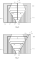
- a first protective field F1 for example in the area near the ground and furthest inside, is not as in the example according to Fig. 4 and Fig. 5 of several or all of the larger protective fields Fj, but extends into the plane E from both sides of the passage 12 (11) to be monitored to form a field boundary each, which runs mirror-symmetrically to the vertical V and/or delimits between them a surface area which is symmetrical to the vertical V and not attributable to the first protective field Fj, in particular which is convex on both sides or opens continuously upwards (see e.g. Fig. 6 to Fig. 10 ).
- the two lateral field parts F1.1; F1.2 of the first protective field F1 (in Fig. 6 to Fig. 10
- the two parts can be connected to one another in the area of the upper and/or lower edge or, as shown, form two parts F1.1; F1.2 of a two-part first protective field F1.
- the first protective field F1 can also be defined exactly the other way around, whereby this is then formed by the inner symmetrical area (not shaded) and a switching logic based on a violation/non-violation of the first protective field F1 (see below) should then be defined exactly the other way around.
- the field boundary(s) of the first protective field Fj converge in the lower edge region of the monitored plane E or end in the lower edge region within the boundaries of a smallest protective field Fj of a group of protective fields Fj, of which the respective protective field Fj - entirely or at least as far as the extension in the horizontal direction and/or, preferably and upwards - is covered by the next larger and/or next wider protective field Fj+1 of the group.
- the field boundaries of the first field F1 diverge on both sides of the vertical V in such a way that they intersect the, in particular lateral, boundaries of several, e.g. at least the two innermost of the group of nested protective fields Fj, and/or widen the surface area formed between them.
- the first protective field F1 extends to the upper edge of the area to be monitored in plane E and intersects the outer boundary of all other protective fields Fj.
- the two lateral field boundaries of the first protective field F1 converge symmetrically towards one another again from a height which corresponds to at least half the height of a roll 17 (15) of maximum diameter D max transported through the passage on the transport means 24, thereby forming the above-mentioned convex shape of the area lying between them.
- the course of the field boundary on both sides of this first protective field F1 can be continuously curved and/or polygonal, i.e. defined in sections by a number of straight lines that continue one another, in this case two in each case.
- the latter is advantageous, for example, in relation to simple parameterization (see e.g. Fig. 6 and Fig. 7 ).
- two or more variants of the above-mentioned monitoring case U1; U2, e.g. several different second monitoring cases U2.1; U2.2 can be provided or maintained, which are subject to the same symmetry type with regard to the evaluation, but whose set of protective fields Fj differs in number, size, gradation and/or shape, and between which, in an advantageous embodiment, a switchover, in particular automatic, takes place or can take place.
- two monitoring cases U2.1; U2.2 with asymmetric field set can be provided, one for use with smaller rollers 17 (16) with a concentration of field boundaries further inside and lower down, see e.g. Fig.8 ) and one for use with larger rolls 17 (16) with a concentration of field boundaries further up and outwards (see e.g. Fig.9 ).
- a basic state ie before an object to be transferred, e.g. a roll 17 (16), means of transport 24 or container, violates a protective field Fj of the monitoring level E
- the monitoring system is in a first monitoring case U1, in which a symmetrical field set is present in the above sense or the evaluation of symmetrical partial areas E1; E2 for field violation takes place (see e.g. partial image a)) in Fig.10 ).
- the edge area If a field violation occurs in the area between the field boundaries of the largest protective field Fk, which extends inwards from the boundaries of the passage 12 (11), and the next smallest protective field Fj, hereinafter also referred to as the edge area, the above-mentioned safety measures are triggered in every case, i.e. regardless of any additional protective field violations that may be present. If a violation of property rights is registered in this edge area, it is assumed that a person or an object of an impermissible size has entered.
- the system switches to a second monitoring case U2, ie monitoring with an asymmetrical field set in the above sense or an evaluation of asymmetrical partial areas E1; E2 for field violation.
- a field violation of the first field F1 F1.1, F1.2
- the system switches to a second monitoring case U2, ie monitoring with an asymmetrical field set in the above sense or an evaluation of asymmetrical partial areas E1; E2 for field violation.
- an object or living being on the roller 17 (16) is more reliably detected. recognizable.
- two or more second monitoring cases U2 can be provided for a higher-level monitoring case U1; U2, namely a first variant U2.1 of the second monitoring case U2 for use with rollers 17 (16) with a diameter D that is smaller than a limit diameter and a second variant U2.2 of the second monitoring case U2 for use with rollers 17 (16) with a diameter D that is larger than a limit diameter.
- the limit diameter can be assigned to one or the other variant.
- the variant U2.1 for smaller roller diameters D is preferably switched to first (see e.g. Fig.8 and Fig. 10b )).
- the system switches to the first monitoring case U1, i.e. to operation with a symmetrical field set or an evaluation of symmetrical partial areas E1; E2 for field violation (see e.g. Fig.6 or Fig. 10 a )).
- a further condition for the activation of the above-mentioned muting function is that the transport means 24 is active on the drive means 28 driving the passage through the passage 12 (11) and/or that the output signal of the sensor 29 located in the transport direction T before entering the monitoring level E indicates the passage of an object before one of the protective fields Fj is violated within a defined time window and/or that the output signal of the sensor 29 located in the transport direction T behind the monitoring level E only indicates the passage of an object after one of the protective fields Fj has been violated within a defined time window and/or the sensor 29 located before entering the monitoring level E has indicated the passage of an object.
Landscapes
- Engineering & Computer Science (AREA)
- General Engineering & Computer Science (AREA)
- Mechanical Engineering (AREA)
- Investigating Materials By The Use Of Optical Means Adapted For Particular Applications (AREA)
- Controlling Rewinding, Feeding, Winding, Or Abnormalities Of Webs (AREA)
- Controlling Sheets Or Webs (AREA)
- Inking, Control Or Cleaning Of Printing Machines (AREA)
Claims (15)
- Procédé de surveillance d'un accès (11; 12) menant à une zone de sécurité (08; 09) d'un dérouleur ou d'un enrouleur de bobine, à travers lequel accès des bobines (16; 17) peuvent être transportées à l'intérieur et/ou à l'extérieur le long d'un chemin de transport, dans lequel l'accès (11; 12) est formé par une ouverture prévue entre deux éléments délimitant mécaniquement la zone de sécurité (08; 09), et dans lequel l'accès (11; 12) est surveillé par une technologie de capteurs de surveillance d'un système de surveillance, dans lequel deux scanners (21) compris dans la technologie de capteurs de surveillance balaient respectivement avec leurs faisceaux de mesure respectifs une zone angulaire se situant dans un même plan (E) se déroulant dans l'ouverture, caractérisé en ce que l'accès (11; 12) est surveillé dans un modèle de champs de protection M(Fj) avec plusieurs champs de protection (Fj) de tailles et/ou de formes différentes, en ce que plusieurs des champs de protection (Fj) de tailles et/ou de formes différentes sont respectivement compris dans un champ de protection suivant plus grand et/ou suivant plus large, entièrement ou au moins dans la largeur et considéré vers le haut, en ce que pour plusieurs de ces champs de protection (Fj) de tailles et/ou de formes différentes les images de balayage des deux scanners (21) dans des zones partielles (E1; E2) du plan (E) différentes l'une de l'autre, se raccordant ou se chevauchant l'une l'autre, sont vérifiées quant à une violation de champ de protection des champs de protection (Fj) concernés de tailles et/ou de formes différentes, et une information sur la validité d'une violation de champ de protection constatée est déduite via une analyse des modèles de violation de champs de protection (Fj) violés, obtenus dans les deux zones partielles.
- Procédé selon la revendication 1, caractérisé en ce que les images de balayage issues des deux scanners (21) sont analysées quant à une violation de champ de protection dans les zones partielles (E1; E2) différentes l'une de l'autre du même champ de protection (Fj) respectivement concerné et/ou en ce que pour la vérification d'une violation de champ de protection sont mis à contribution des champs de protection (Fj) qui s'étendent dans le plan (E) en symétrie spéculaire par rapport à une verticale (V) coupant au milieu le chemin de transport dans le plan (E).
- Procédé selon la revendication 1 ou 2, caractérisé en ce que des moyens d'analyse (23) surveillent les images de balayage livrées par les deux scanners (21) dans les deux zones partielles du plan (E) différentes et recouvrant cependant par leur somme au moins la totalité de la zone surveillée quant à une pénétration d'un objet dans un ou plusieurs des champs de protection (Fj) de tailles et/ou de formes différentes, et analysent ainsi si, lors de l'apparition d'une perturbation, c'est-à-dire d'une violation de champ de protection dans au moins un des champs de protection (Fj), sont constatés, via les images de balayage des deux scanners (21), des mêmes modèles de violation par-dessus les champs de protection (Fj) à considérer ou des modèles de violation qui s'écartent l'un de l'autre uniquement d'un nombre définissable de champs de protection (Fj) suivants plus grands ou plus larges et/ou plus hauts.
- Procédé selon la revendication 1, 2 ou 3, caractérisé en ce que les zones partielles (E1; E2) analysées quant à une violation de champ se trouvent dans au moins une situation de fonctionnement et/ou un premier cas de surveillance (U1) en symétrie par rapport à une verticale (V) et/ou dans au moins une situation de fonctionnement et/ou un second cas de surveillance (U2; U2.1; U2.2) en asymétrie par rapport à une verticale (V), qui se déroule dans le plan (E) et coupe au milieu le chemin de transport menant à travers le passage considéré transversalement par rapport à la direction de transport.
- Procédé selon la revendication 4, caractérisé en ce qu'une commutation entre le premier et le deuxième cas de surveillance (U2; U2.1; U2.2) ou l'une parmi plusieurs variantes (U2.1; U2.2) du deuxième cas de surveillance (U2) s'effectue en fonction de l'apparition d'une violation d'un premier champ de protection (F1 ; F1.1 ; F1.2) des plusieurs champs de protection (Fj), dans lequel- la surveillance dans le champ précédant le passage à travers d'une bobine (16; 17) à transférer se produit dans le premier cas de surveillance (U1),- lors du constat d'une violation de champ du premier champ (F1; F1.1; F1.2), une commutation est réalisée vers un second cas de surveillance (U2; U2.1; U2.2),- la surveillance lors du fonctionnement dans le second cas de surveillance (U2) ou l'une de ses variantes (U2.1; U2.2) pour le cas où le premier champ de protection (F1) n'est plus violé, cependant un ou plusieurs des champs de protection (Fj) restants est ou sont violé (s), une commutation est réalisée vers le premier cas de surveillance (U1).
- Procédé selon la revendication 1, 2, 3, 4 ou 5, caractérisé en ce que l'accès (11; 12) est surveillé dans un modèle de champs de protection M(Fj), lequel comprend au moins un champ de protection (Fj) qui est agencé et conçu de sorte qu'il soit compris au moins dans sa largeur et/ou en allant vers le haut dans le champ de protection (Fj+1) suivant plus grand et/ou dans un modèle de champs de protection M(Fj) extrait d'un nombre k de champs de protection (Fj), lequel dans le nombre k de champs de protection (Fj) comprend une pluralité de champs de protection (Fj) imbriqués les uns dans les autres de sorte qu'un champ de protection (Fj) respectif de cette pluralité soit respectivement compris entièrement ou au moins dans sa largeur et/ou en allant vers le haut dans un champ de protection (Fj+1) suivant plus grand, et/ou en ce qu'une surveillance du passage (11; 12) se produit dans 4 à 12 niveaux de champ de protection et/ou en utilisant une pluralité de 3 à 11 champs de protection (Fj) imbriqués les uns dans les autres de sorte qu'un champ de protection (Fj) respectif de cette pluralité soit respectivement compris entièrement ou au moins dans sa largeur et/ou en allant vers le haut dans un champ de protection (Fj+1) se terminant suivant plus grand ou suivant plus large et/ou suivant plus haut.
- Procédé selon la revendication 1, 2, 3, 4, 5 ou 6, caractérisé en ce que pour le cas où pendant un passage d'un objet (16; 17) pour les deux zones partielles (E1; E2) sont constatés, via les images de balayage des deux scanners (21), des mêmes modèles de violation par-dessus les champs de protection (Fj) à considérer ou des modèles de violation qui s'écartent l'un de l'autre uniquement d'un nombre définissable de champs de protection (Fj) suivants plus grands et/ou plus larges, pour le ou les champ(s) de protection (Fj) concerné(s) par la violation un déclenchement de mesures de sécurité est réprimé, c'est-à-dire que ce qu'on appelle une fonction d'inhibition est activée, et lors d'un écart partant de là dans les deux modèles de violation constatés est mise en œuvre une mesure de sécurité.
- Dispositif de surveillance d'un accès (11; 12) menant à une zone de sécurité (08; 09) d'un dérouleur ou d'un enrouleur de bobine (03; 04), à travers lequel accès des bobines (16; 17) peuvent être transportées à l'intérieur et/ou à l'extérieur, en particulier pour l'exécution du procédé selon l'une des revendications 1 à 7, dans lequel l'accès (11; 12) est formé par une ouverture prévue entre deux éléments délimitant mécaniquement la zone de sécurité (08; 09), et dans lequel une technologie de capteurs de surveillance est prévue pour la surveillance de l'accès (11; 12), dans lequel la technologie de capteurs de surveillance comprend deux scanners (21) dont les faisceaux de mesure balaient respectivement une zone angulaire se situant dans un même plan (E) se déroulant dans l'ouverture, caractérisé en ce que pour la surveillance de l'accès (11; 12) est prévu un modèle de champs de protection M(Fj) avec plusieurs champs de protection (Fj) de tailles et/ou de formes différentes, desquels plusieurs est ou sont compris, entièrement ou au moins dans la largeur et considéré vers le haut, dans respectivement un champ de protection suivant plus grand et/ou plus large, et en ce que des moyens d'analyse (23) sont compris via lesquels, pour plusieurs de ces champs de protection (Fj) de tailles et/ou de formes différentes, les images de balayage des deux scanners (21) dans des zones partielles (E1; E2) du plan (E) différentes l'une de l'autre, se raccordant ou se chevauchant l'une l'autre, sont et/ou peuvent être vérifiées quant à une violation de champ de protection des champs de protection (Fj) concernés de tailles et/ou de formes différentes.
- Dispositif selon la revendication 8, caractérisé en ce que via les moyens d'analyse (23) les images de balayage des deux scanners (21) peuvent être analysées quant à une violation de champ de protection dans les zones partielles différentes l'une de l'autre du respectivement même champ de protection (Fj) se situant dans le plan (E) et/ou une information sur la validité d'une violation de champ de protection constatée peut être déduite via une analyse des modèles, obtenus dans les deux zones partielles, de violation de champs de protection (Fj) violés.
- Dispositif selon la revendication 8 ou 9, caractérisé en ce que les deux scanners (21) sont agencés des deux côtés du chemin de transport et/ou sont agencés à une même hauteur et/ou par-dessus le côté supérieur d'une bobine (16; 17) transportée de diamètre maximal à utiliser (Dmax) et/ou sont agencés en symétrie axiale par rapport à une verticale (V) qui se déroule dans le plan de surveillance (E) et se situe au milieu par rapport au chemin de transport menant à travers le passage.
- Dispositif selon la revendication 8, 9 ou 10, caractérisé en ce que les ou plusieurs des champs de protection (Fj) mis à contribution pour la vérification d'une violation de champ de protection s'étendent dans le plan (E) en symétrie spéculaire par rapport à une verticale (V) séparant de manière centrale le chemin de transport dans le plan (E).
- Dispositif selon la revendication 11, caractérisé en ce qu'un premier champ de protection (F1) est prévu de sorte qu'il chevauche partiellement au moins un le plus petit des champs de protection (Fj) se situant les uns dans les autres et/ou en ce qu'il s'étend dans le plan (E) depuis les deux côtés du passage (11; 12) à surveiller jusqu'à chacune une limite de champ qui délimitent entre elles une zone de surface symétrique par rapport à une verticale (V) et à ne pas compter dans le premier champ de protection (F1).
- Dispositif selon la revendication 8, 9, 10, 11 ou 12, caractérisé en ce que les moyens d'analyse (23) sont aménagés pour surveiller les images de balayage livrées par les deux scanners (21) dans les deux zones partielles du plan (E) différentes et recouvrant cependant par leur somme au moins la totalité de la zone surveillée quant à une pénétration d'un objet dans un ou plusieurs des champs de protection (Fj) de tailles et/ou de formes différentes, et analyser ainsi si, lors de l'apparition d'une perturbation, c'est-à-dire d'une violation de champ de protection dans au moins un des champs de protection (Fj), sont constatés, via les images de balayage des deux scanners (21), des mêmes modèles de violation par-dessus les champs de protection (Fj) à considérer ou des modèles de violation qui s'écartent l'un de l'autre uniquement d'un nombre définissable de champs de protection (Fj) suivants plus grands et/ou plus larges.
- Machine d'impression avec un dérouleur de bobine (03) depuis lequel un support d'impression (02) en forme de bande peut être déroulé et/ou un enrouleur de bobine (04) sur lequel un support d'impression (02) en forme de bande et imprimé au préalable peut être enroulé, et avec un groupe d'impression (01), dans laquelle une zone de sécurité (08; 09) s'étend sur au moins le côté d'utilisation du dérouleur de bobine (03) et/ou de l'enrouleur de bobine (04), laquelle est limitée par le dérouleur ou l'enrouleur (03; 04) lui-même ainsi que par un ou plusieurs agrégats se raccordant et/ou des équipements d'arrêt (13) mécaniques et comprend au moins un premier accès (11; 12) surveillé par technologie de capteurs, à travers lequel accès des bobines (16; 17) peuvent être transportées à l'intérieur et/ou à l'extérieur de la zone de sécurité (08; 09), caractérisée par un dispositif selon l'une des revendications 8 à 13.
- Machine d'impression selon la revendication 14, caractérisée en ce que le groupe d'impression (01) est conçu en tant que groupe d'impression (01) travaillant selon un procédé d'impression démuni de forme d'impression et/ou en tant que groupe d'impression présentant des têtes d'impression à jet d'encre.
Applications Claiming Priority (2)
| Application Number | Priority Date | Filing Date | Title |
|---|---|---|---|
| DE102020119565.6A DE102020119565B4 (de) | 2020-07-24 | 2020-07-24 | Verfahren und Vorrichtung zur Überwachung eines in einen Sicherheitsbereich eines Rollenab- oder -aufwicklers führenden Zuganges sowie Rollendruckmaschine |
| PCT/EP2021/057387 WO2022017652A1 (fr) | 2020-07-24 | 2021-03-23 | Procédé et dispositif de surveillance d'un point d'accès débouchant dans une zone de sécurité d'une enrouleuse ou d'une dérouleuse à rouleaux, et machine d'impression |
Publications (2)
| Publication Number | Publication Date |
|---|---|
| EP4118375A1 EP4118375A1 (fr) | 2023-01-18 |
| EP4118375B1 true EP4118375B1 (fr) | 2024-04-24 |
Family
ID=75339687
Family Applications (1)
| Application Number | Title | Priority Date | Filing Date |
|---|---|---|---|
| EP21715800.5A Active EP4118375B1 (fr) | 2020-07-24 | 2021-03-23 | Procédé et dispositif de surveillance d'un point d'accès débouchant dans une zone de sécurité d'une enrouleuse ou d'une dérouleuse à rouleaux, et machine d'impression |
Country Status (5)
| Country | Link |
|---|---|
| US (1) | US11660855B2 (fr) |
| EP (1) | EP4118375B1 (fr) |
| CN (1) | CN115552164B (fr) |
| DE (1) | DE102020119565B4 (fr) |
| WO (1) | WO2022017652A1 (fr) |
Families Citing this family (5)
| Publication number | Priority date | Publication date | Assignee | Title |
|---|---|---|---|---|
| DE102022210508A1 (de) * | 2022-10-05 | 2024-04-11 | Bhs Corrugated Maschinen- Und Anlagenbau Gmbh | Materialbahn-Abrollanordnung |
| JP2024075253A (ja) * | 2022-11-22 | 2024-06-03 | 株式会社リコー | 印刷装置、印刷システム、印刷方法及びプログラム |
| DE102023115311B4 (de) | 2023-06-13 | 2025-07-03 | Sick Ag | Zugangsabsicherungssystem |
| DE202023103223U1 (de) | 2023-06-13 | 2024-09-16 | Sick Ag | Zugangsabsicherungssystem |
| DE202023107245U1 (de) * | 2023-12-07 | 2025-03-12 | Leuze Electronic Gmbh & Co. Kg | Sensoranordnung |
Family Cites Families (11)
| Publication number | Priority date | Publication date | Assignee | Title |
|---|---|---|---|---|
| DE102006029643B4 (de) | 2006-06-28 | 2008-10-09 | Leuze Lumiflex Gmbh + Co. Kg | Vorrichtung zur Überwachung eines Gefahrenbereichs |
| DE102010001014A1 (de) * | 2010-01-19 | 2011-09-08 | Koenig & Bauer Aktiengesellschaft | Rollenwechsler mit einer Absicherung eines Sicherheitsbereiches |
| DE102010031650A1 (de) | 2010-07-22 | 2012-01-26 | Koenig & Bauer Aktiengesellschaft | Rollenwechsler mit Sicherheitseinrichtung |
| DE102012211708B4 (de) * | 2012-07-05 | 2015-07-09 | Koenig & Bauer Aktiengesellschaft | Rollenversorgungssystem einer Rollendruckmaschine, Rollendruckmaschine sowie Verfahren zur Bedienung eines Rollenversorgungssystems einer Rollendruckmaschine |
| CN105793179B (zh) * | 2013-12-04 | 2017-07-14 | 柯尼格及包尔公开股份有限公司 | 处理单张纸的机器的输出装置以及用于使处理单张纸的机器运行的方法 |
| US9910186B2 (en) * | 2015-08-17 | 2018-03-06 | Rockwell Automation Safety Ag | Dynamic light curtain muting system and method |
| DE102016125595B4 (de) | 2016-12-23 | 2019-09-12 | Sick Ag | Zugangsabsicherungssystem |
| DE202017103399U1 (de) | 2017-06-06 | 2018-09-07 | Sick Ag | Zugangsabsicherungssystem |
| EP3415804B1 (fr) | 2017-06-16 | 2021-04-14 | Leuze electronic GmbH + Co. KG | Dispositif de sécurité |
| DE102017211828A1 (de) | 2017-07-11 | 2019-01-17 | Koenig & Bauer Ag | Druckmaschine mit einem Rollenabwickler sowie Verfahren zur Handhabung von Rollen bahnförmigen Material |
| DE102019116806B4 (de) | 2019-06-21 | 2023-07-20 | Wilhelm B a h m ü l l e r Maschinenbau Präzisionswerkzeuge GmbH | Vorrichtung und Verfahren zur Überwachung eines Gefahrenbereichs |
-
2020
- 2020-07-24 DE DE102020119565.6A patent/DE102020119565B4/de not_active Expired - Fee Related
-
2021
- 2021-03-23 EP EP21715800.5A patent/EP4118375B1/fr active Active
- 2021-03-23 US US17/925,043 patent/US11660855B2/en active Active
- 2021-03-23 WO PCT/EP2021/057387 patent/WO2022017652A1/fr not_active Ceased
- 2021-03-23 CN CN202180034846.5A patent/CN115552164B/zh not_active Expired - Fee Related
Also Published As
| Publication number | Publication date |
|---|---|
| CN115552164A (zh) | 2022-12-30 |
| DE102020119565B4 (de) | 2022-04-28 |
| DE102020119565A1 (de) | 2022-01-27 |
| US11660855B2 (en) | 2023-05-30 |
| CN115552164B (zh) | 2023-08-29 |
| US20230132779A1 (en) | 2023-05-04 |
| WO2022017652A1 (fr) | 2022-01-27 |
| EP4118375A1 (fr) | 2023-01-18 |
Similar Documents
| Publication | Publication Date | Title |
|---|---|---|
| EP4118375B1 (fr) | Procédé et dispositif de surveillance d'un point d'accès débouchant dans une zone de sécurité d'une enrouleuse ou d'une dérouleuse à rouleaux, et machine d'impression | |
| EP3425256B1 (fr) | Système de protection d'accès | |
| DE102016125595B4 (de) | Zugangsabsicherungssystem | |
| EP2017524B1 (fr) | Barrière lumineuse | |
| EP2346762A1 (fr) | Protection de zone de danger pour la zone de garnissage automatique sur un changeur de bobine | |
| AT506835B1 (de) | Verfahren zum sichern eines anfahrstranges in einer stranggiessanlage und stranggiessanlage mit einem anfahrstrang | |
| WO2015185351A1 (fr) | Procédé permettant de faire fonctionner une installation d'usinage de panneaux, et installation d'usinage de panneaux | |
| EP2037297B1 (fr) | Détection d'objet et barrière lumineuse | |
| EP1662349B1 (fr) | Protection de machines dépendant des conditions des machines | |
| EP3754244A1 (fr) | Dispositif et procédé de surveillance d'une zone dangereuse | |
| EP1873442B2 (fr) | Méthode et dispositif pour effectuer la surveillance de la sécurité d'un passage | |
| EP4046918A1 (fr) | Protection contre l'accès pour une station de travail d'une machine d'emballage | |
| EP3660251B1 (fr) | Dispositif de protection, en particulier portail industriel | |
| DE202017103399U1 (de) | Zugangsabsicherungssystem | |
| DE102008033195B4 (de) | Bearbeitungszentrum mit einer Werkstücktransporteinrichtung und einem Werkstückbereitstellungsplatz mit opto-elektronischer Schutzeinrichtung | |
| EP3239367B1 (fr) | Procédé de fonctionnement d'un brise-balles et brise-balles | |
| DE102017110538B4 (de) | Zugangsabsicherungssystem | |
| EP1499551A1 (fr) | Procede et dispositif pour detecter une rupture de bande sur une machine d'usinage de bande | |
| EP0674982A1 (fr) | Dispositif de granulation pour matériau filiforme | |
| DE19506463A1 (de) | Stauüberwachungseinrichtung für eine Transportvorrichtung für Papier, insbesondere für eine Papierbahn | |
| EP1760019A2 (fr) | Dispositif de surveillance des ruptures de bande dans une machine rotative d'impression | |
| DE102017211828A1 (de) | Druckmaschine mit einem Rollenabwickler sowie Verfahren zur Handhabung von Rollen bahnförmigen Material | |
| DE10259538A1 (de) | Bahnbehandlungsvorrichtung | |
| DE202017102922U1 (de) | Zugangsabsicherungssystem | |
| EP4730064A1 (fr) | Système de contrôle d'une transition entre une première zone et une seconde zone dans un environnement de fonctionnement |
Legal Events
| Date | Code | Title | Description |
|---|---|---|---|
| STAA | Information on the status of an ep patent application or granted ep patent |
Free format text: STATUS: UNKNOWN |
|
| STAA | Information on the status of an ep patent application or granted ep patent |
Free format text: STATUS: THE INTERNATIONAL PUBLICATION HAS BEEN MADE |
|
| PUAI | Public reference made under article 153(3) epc to a published international application that has entered the european phase |
Free format text: ORIGINAL CODE: 0009012 |
|
| STAA | Information on the status of an ep patent application or granted ep patent |
Free format text: STATUS: REQUEST FOR EXAMINATION WAS MADE |
|
| 17P | Request for examination filed |
Effective date: 20221011 |
|
| AK | Designated contracting states |
Kind code of ref document: A1 Designated state(s): AL AT BE BG CH CY CZ DE DK EE ES FI FR GB GR HR HU IE IS IT LI LT LU LV MC MK MT NL NO PL PT RO RS SE SI SK SM TR |
|
| DAV | Request for validation of the european patent (deleted) | ||
| DAX | Request for extension of the european patent (deleted) | ||
| RIC1 | Information provided on ipc code assigned before grant |
Ipc: B65H 26/08 20060101ALI20231012BHEP Ipc: B65H 19/30 20060101ALI20231012BHEP Ipc: B65H 19/12 20060101ALI20231012BHEP Ipc: B41J 15/04 20060101ALI20231012BHEP Ipc: B41F 33/00 20060101ALI20231012BHEP Ipc: F16P 3/14 20060101AFI20231012BHEP |
|
| GRAP | Despatch of communication of intention to grant a patent |
Free format text: ORIGINAL CODE: EPIDOSNIGR1 |
|
| STAA | Information on the status of an ep patent application or granted ep patent |
Free format text: STATUS: GRANT OF PATENT IS INTENDED |
|
| INTG | Intention to grant announced |
Effective date: 20231127 |
|
| GRAJ | Information related to disapproval of communication of intention to grant by the applicant or resumption of examination proceedings by the epo deleted |
Free format text: ORIGINAL CODE: EPIDOSDIGR1 |
|
| STAA | Information on the status of an ep patent application or granted ep patent |
Free format text: STATUS: REQUEST FOR EXAMINATION WAS MADE |
|
| GRAP | Despatch of communication of intention to grant a patent |
Free format text: ORIGINAL CODE: EPIDOSNIGR1 |
|
| STAA | Information on the status of an ep patent application or granted ep patent |
Free format text: STATUS: GRANT OF PATENT IS INTENDED |
|
| INTC | Intention to grant announced (deleted) | ||
| GRAS | Grant fee paid |
Free format text: ORIGINAL CODE: EPIDOSNIGR3 |
|
| GRAA | (expected) grant |
Free format text: ORIGINAL CODE: 0009210 |
|
| STAA | Information on the status of an ep patent application or granted ep patent |
Free format text: STATUS: THE PATENT HAS BEEN GRANTED |
|
| INTG | Intention to grant announced |
Effective date: 20240304 |
|
| AK | Designated contracting states |
Kind code of ref document: B1 Designated state(s): AL AT BE BG CH CY CZ DE DK EE ES FI FR GB GR HR HU IE IS IT LI LT LU LV MC MK MT NL NO PL PT RO RS SE SI SK SM TR |
|
| REG | Reference to a national code |
Ref country code: GB Ref legal event code: FG4D Free format text: NOT ENGLISH |
|
| REG | Reference to a national code |
Ref country code: CH Ref legal event code: EP |
|
| REG | Reference to a national code |
Ref country code: DE Ref legal event code: R096 Ref document number: 502021003473 Country of ref document: DE |
|
| REG | Reference to a national code |
Ref country code: IE Ref legal event code: FG4D Free format text: LANGUAGE OF EP DOCUMENT: GERMAN |
|
| REG | Reference to a national code |
Ref country code: NL Ref legal event code: FP |
|
| REG | Reference to a national code |
Ref country code: LT Ref legal event code: MG9D |
|
| PG25 | Lapsed in a contracting state [announced via postgrant information from national office to epo] |
Ref country code: IS Free format text: LAPSE BECAUSE OF FAILURE TO SUBMIT A TRANSLATION OF THE DESCRIPTION OR TO PAY THE FEE WITHIN THE PRESCRIBED TIME-LIMIT Effective date: 20240824 |
|
| PG25 | Lapsed in a contracting state [announced via postgrant information from national office to epo] |
Ref country code: BG Free format text: LAPSE BECAUSE OF FAILURE TO SUBMIT A TRANSLATION OF THE DESCRIPTION OR TO PAY THE FEE WITHIN THE PRESCRIBED TIME-LIMIT Effective date: 20240424 |
|
| PG25 | Lapsed in a contracting state [announced via postgrant information from national office to epo] |
Ref country code: HR Free format text: LAPSE BECAUSE OF FAILURE TO SUBMIT A TRANSLATION OF THE DESCRIPTION OR TO PAY THE FEE WITHIN THE PRESCRIBED TIME-LIMIT Effective date: 20240424 Ref country code: FI Free format text: LAPSE BECAUSE OF FAILURE TO SUBMIT A TRANSLATION OF THE DESCRIPTION OR TO PAY THE FEE WITHIN THE PRESCRIBED TIME-LIMIT Effective date: 20240424 |
|
| PG25 | Lapsed in a contracting state [announced via postgrant information from national office to epo] |
Ref country code: GR Free format text: LAPSE BECAUSE OF FAILURE TO SUBMIT A TRANSLATION OF THE DESCRIPTION OR TO PAY THE FEE WITHIN THE PRESCRIBED TIME-LIMIT Effective date: 20240725 |
|
| PG25 | Lapsed in a contracting state [announced via postgrant information from national office to epo] |
Ref country code: PT Free format text: LAPSE BECAUSE OF FAILURE TO SUBMIT A TRANSLATION OF THE DESCRIPTION OR TO PAY THE FEE WITHIN THE PRESCRIBED TIME-LIMIT Effective date: 20240826 |
|
| PG25 | Lapsed in a contracting state [announced via postgrant information from national office to epo] |
Ref country code: ES Free format text: LAPSE BECAUSE OF FAILURE TO SUBMIT A TRANSLATION OF THE DESCRIPTION OR TO PAY THE FEE WITHIN THE PRESCRIBED TIME-LIMIT Effective date: 20240424 |
|
| PG25 | Lapsed in a contracting state [announced via postgrant information from national office to epo] |
Ref country code: PL Free format text: LAPSE BECAUSE OF FAILURE TO SUBMIT A TRANSLATION OF THE DESCRIPTION OR TO PAY THE FEE WITHIN THE PRESCRIBED TIME-LIMIT Effective date: 20240424 |
|
| PG25 | Lapsed in a contracting state [announced via postgrant information from national office to epo] |
Ref country code: LV Free format text: LAPSE BECAUSE OF FAILURE TO SUBMIT A TRANSLATION OF THE DESCRIPTION OR TO PAY THE FEE WITHIN THE PRESCRIBED TIME-LIMIT Effective date: 20240424 |
|
| PG25 | Lapsed in a contracting state [announced via postgrant information from national office to epo] |
Ref country code: PT Free format text: LAPSE BECAUSE OF FAILURE TO SUBMIT A TRANSLATION OF THE DESCRIPTION OR TO PAY THE FEE WITHIN THE PRESCRIBED TIME-LIMIT Effective date: 20240826 Ref country code: PL Free format text: LAPSE BECAUSE OF FAILURE TO SUBMIT A TRANSLATION OF THE DESCRIPTION OR TO PAY THE FEE WITHIN THE PRESCRIBED TIME-LIMIT Effective date: 20240424 Ref country code: NO Free format text: LAPSE BECAUSE OF FAILURE TO SUBMIT A TRANSLATION OF THE DESCRIPTION OR TO PAY THE FEE WITHIN THE PRESCRIBED TIME-LIMIT Effective date: 20240724 Ref country code: LV Free format text: LAPSE BECAUSE OF FAILURE TO SUBMIT A TRANSLATION OF THE DESCRIPTION OR TO PAY THE FEE WITHIN THE PRESCRIBED TIME-LIMIT Effective date: 20240424 Ref country code: IS Free format text: LAPSE BECAUSE OF FAILURE TO SUBMIT A TRANSLATION OF THE DESCRIPTION OR TO PAY THE FEE WITHIN THE PRESCRIBED TIME-LIMIT Effective date: 20240824 Ref country code: HR Free format text: LAPSE BECAUSE OF FAILURE TO SUBMIT A TRANSLATION OF THE DESCRIPTION OR TO PAY THE FEE WITHIN THE PRESCRIBED TIME-LIMIT Effective date: 20240424 Ref country code: GR Free format text: LAPSE BECAUSE OF FAILURE TO SUBMIT A TRANSLATION OF THE DESCRIPTION OR TO PAY THE FEE WITHIN THE PRESCRIBED TIME-LIMIT Effective date: 20240725 Ref country code: FI Free format text: LAPSE BECAUSE OF FAILURE TO SUBMIT A TRANSLATION OF THE DESCRIPTION OR TO PAY THE FEE WITHIN THE PRESCRIBED TIME-LIMIT Effective date: 20240424 Ref country code: ES Free format text: LAPSE BECAUSE OF FAILURE TO SUBMIT A TRANSLATION OF THE DESCRIPTION OR TO PAY THE FEE WITHIN THE PRESCRIBED TIME-LIMIT Effective date: 20240424 Ref country code: BG Free format text: LAPSE BECAUSE OF FAILURE TO SUBMIT A TRANSLATION OF THE DESCRIPTION OR TO PAY THE FEE WITHIN THE PRESCRIBED TIME-LIMIT Effective date: 20240424 Ref country code: RS Free format text: LAPSE BECAUSE OF FAILURE TO SUBMIT A TRANSLATION OF THE DESCRIPTION OR TO PAY THE FEE WITHIN THE PRESCRIBED TIME-LIMIT Effective date: 20240724 |
|
| PG25 | Lapsed in a contracting state [announced via postgrant information from national office to epo] |
Ref country code: DK Free format text: LAPSE BECAUSE OF FAILURE TO SUBMIT A TRANSLATION OF THE DESCRIPTION OR TO PAY THE FEE WITHIN THE PRESCRIBED TIME-LIMIT Effective date: 20240424 |
|
| PG25 | Lapsed in a contracting state [announced via postgrant information from national office to epo] |
Ref country code: EE Free format text: LAPSE BECAUSE OF FAILURE TO SUBMIT A TRANSLATION OF THE DESCRIPTION OR TO PAY THE FEE WITHIN THE PRESCRIBED TIME-LIMIT Effective date: 20240424 |
|
| PG25 | Lapsed in a contracting state [announced via postgrant information from national office to epo] |
Ref country code: CZ Free format text: LAPSE BECAUSE OF FAILURE TO SUBMIT A TRANSLATION OF THE DESCRIPTION OR TO PAY THE FEE WITHIN THE PRESCRIBED TIME-LIMIT Effective date: 20240424 |
|
| PG25 | Lapsed in a contracting state [announced via postgrant information from national office to epo] |
Ref country code: SK Free format text: LAPSE BECAUSE OF FAILURE TO SUBMIT A TRANSLATION OF THE DESCRIPTION OR TO PAY THE FEE WITHIN THE PRESCRIBED TIME-LIMIT Effective date: 20240424 Ref country code: RO Free format text: LAPSE BECAUSE OF FAILURE TO SUBMIT A TRANSLATION OF THE DESCRIPTION OR TO PAY THE FEE WITHIN THE PRESCRIBED TIME-LIMIT Effective date: 20240424 |
|
| REG | Reference to a national code |
Ref country code: DE Ref legal event code: R097 Ref document number: 502021003473 Country of ref document: DE |
|
| PG25 | Lapsed in a contracting state [announced via postgrant information from national office to epo] |
Ref country code: SM Free format text: LAPSE BECAUSE OF FAILURE TO SUBMIT A TRANSLATION OF THE DESCRIPTION OR TO PAY THE FEE WITHIN THE PRESCRIBED TIME-LIMIT Effective date: 20240424 |
|
| PG25 | Lapsed in a contracting state [announced via postgrant information from national office to epo] |
Ref country code: SM Free format text: LAPSE BECAUSE OF FAILURE TO SUBMIT A TRANSLATION OF THE DESCRIPTION OR TO PAY THE FEE WITHIN THE PRESCRIBED TIME-LIMIT Effective date: 20240424 Ref country code: SK Free format text: LAPSE BECAUSE OF FAILURE TO SUBMIT A TRANSLATION OF THE DESCRIPTION OR TO PAY THE FEE WITHIN THE PRESCRIBED TIME-LIMIT Effective date: 20240424 Ref country code: RO Free format text: LAPSE BECAUSE OF FAILURE TO SUBMIT A TRANSLATION OF THE DESCRIPTION OR TO PAY THE FEE WITHIN THE PRESCRIBED TIME-LIMIT Effective date: 20240424 Ref country code: EE Free format text: LAPSE BECAUSE OF FAILURE TO SUBMIT A TRANSLATION OF THE DESCRIPTION OR TO PAY THE FEE WITHIN THE PRESCRIBED TIME-LIMIT Effective date: 20240424 Ref country code: DK Free format text: LAPSE BECAUSE OF FAILURE TO SUBMIT A TRANSLATION OF THE DESCRIPTION OR TO PAY THE FEE WITHIN THE PRESCRIBED TIME-LIMIT Effective date: 20240424 Ref country code: CZ Free format text: LAPSE BECAUSE OF FAILURE TO SUBMIT A TRANSLATION OF THE DESCRIPTION OR TO PAY THE FEE WITHIN THE PRESCRIBED TIME-LIMIT Effective date: 20240424 |
|
| PLBE | No opposition filed within time limit |
Free format text: ORIGINAL CODE: 0009261 |
|
| STAA | Information on the status of an ep patent application or granted ep patent |
Free format text: STATUS: NO OPPOSITION FILED WITHIN TIME LIMIT |
|
| 26N | No opposition filed |
Effective date: 20250127 |
|
| PG25 | Lapsed in a contracting state [announced via postgrant information from national office to epo] |
Ref country code: SI Free format text: LAPSE BECAUSE OF FAILURE TO SUBMIT A TRANSLATION OF THE DESCRIPTION OR TO PAY THE FEE WITHIN THE PRESCRIBED TIME-LIMIT Effective date: 20240424 |
|
| PGFP | Annual fee paid to national office [announced via postgrant information from national office to epo] |
Ref country code: AT Payment date: 20250417 Year of fee payment: 5 |
|
| PG25 | Lapsed in a contracting state [announced via postgrant information from national office to epo] |
Ref country code: SE Free format text: LAPSE BECAUSE OF FAILURE TO SUBMIT A TRANSLATION OF THE DESCRIPTION OR TO PAY THE FEE WITHIN THE PRESCRIBED TIME-LIMIT Effective date: 20240424 |
|
| PG25 | Lapsed in a contracting state [announced via postgrant information from national office to epo] |
Ref country code: MC Free format text: LAPSE BECAUSE OF FAILURE TO SUBMIT A TRANSLATION OF THE DESCRIPTION OR TO PAY THE FEE WITHIN THE PRESCRIBED TIME-LIMIT Effective date: 20240424 |
|
| REG | Reference to a national code |
Ref country code: CH Ref legal event code: H13 Free format text: ST27 STATUS EVENT CODE: U-0-0-H10-H13 (AS PROVIDED BY THE NATIONAL OFFICE) Effective date: 20251023 |
|
| REG | Reference to a national code |
Ref country code: NL Ref legal event code: MM Effective date: 20250401 |
|
| PG25 | Lapsed in a contracting state [announced via postgrant information from national office to epo] |
Ref country code: LU Free format text: LAPSE BECAUSE OF NON-PAYMENT OF DUE FEES Effective date: 20250323 |
|
| GBPC | Gb: european patent ceased through non-payment of renewal fee |
Effective date: 20250323 |
|
| REG | Reference to a national code |
Ref country code: BE Ref legal event code: MM Effective date: 20250331 |
|
| PG25 | Lapsed in a contracting state [announced via postgrant information from national office to epo] |
Ref country code: NL Free format text: LAPSE BECAUSE OF NON-PAYMENT OF DUE FEES Effective date: 20250401 |
|
| PG25 | Lapsed in a contracting state [announced via postgrant information from national office to epo] |
Ref country code: GB Free format text: LAPSE BECAUSE OF NON-PAYMENT OF DUE FEES Effective date: 20250323 |
|
| PG25 | Lapsed in a contracting state [announced via postgrant information from national office to epo] |
Ref country code: FR Free format text: LAPSE BECAUSE OF NON-PAYMENT OF DUE FEES Effective date: 20250331 |
|
| PG25 | Lapsed in a contracting state [announced via postgrant information from national office to epo] |
Ref country code: BE Free format text: LAPSE BECAUSE OF NON-PAYMENT OF DUE FEES Effective date: 20250331 |
|
| PG25 | Lapsed in a contracting state [announced via postgrant information from national office to epo] |
Ref country code: CH Free format text: LAPSE BECAUSE OF NON-PAYMENT OF DUE FEES Effective date: 20250331 |
|
| PG25 | Lapsed in a contracting state [announced via postgrant information from national office to epo] |
Ref country code: IE Free format text: LAPSE BECAUSE OF NON-PAYMENT OF DUE FEES Effective date: 20250323 |
|
| PG25 | Lapsed in a contracting state [announced via postgrant information from national office to epo] |
Ref country code: IT Free format text: LAPSE BECAUSE OF FAILURE TO SUBMIT A TRANSLATION OF THE DESCRIPTION OR TO PAY THE FEE WITHIN THE PRESCRIBED TIME-LIMIT Effective date: 20240424 |
|
| PGFP | Annual fee paid to national office [announced via postgrant information from national office to epo] |
Ref country code: DE Payment date: 20260305 Year of fee payment: 6 |