EP4119016B1 - Dispositif de préparation des aliments pourvu d'un accessoire en plusieurs parties - Google Patents
Dispositif de préparation des aliments pourvu d'un accessoire en plusieurs parties Download PDFInfo
- Publication number
- EP4119016B1 EP4119016B1 EP21185470.8A EP21185470A EP4119016B1 EP 4119016 B1 EP4119016 B1 EP 4119016B1 EP 21185470 A EP21185470 A EP 21185470A EP 4119016 B1 EP4119016 B1 EP 4119016B1
- Authority
- EP
- European Patent Office
- Prior art keywords
- food preparation
- attachment
- container
- food
- locking
- Prior art date
- Legal status (The legal status is an assumption and is not a legal conclusion. Google has not performed a legal analysis and makes no representation as to the accuracy of the status listed.)
- Active
Links
Images




Classifications
-
- A—HUMAN NECESSITIES
- A47—FURNITURE; DOMESTIC ARTICLES OR APPLIANCES; COFFEE MILLS; SPICE MILLS; SUCTION CLEANERS IN GENERAL
- A47J—KITCHEN EQUIPMENT; COFFEE MILLS; SPICE MILLS; APPARATUS FOR MAKING BEVERAGES
- A47J43/00—Implements for preparing or holding food, not provided for in other groups of this subclass
- A47J43/04—Machines for domestic use not covered elsewhere, e.g. for grinding, mixing, stirring, kneading, emulsifying, whipping or beating foodstuffs, e.g. power-driven
- A47J43/07—Parts or details, e.g. mixing tools, whipping tools
- A47J43/075—Safety devices
- A47J43/0761—Safety devices for machines with tools driven from the lower side
- A47J43/0772—Safety devices for machines with tools driven from the lower side activated by the proper positioning of the cover
- A47J43/0777—Safety devices for machines with tools driven from the lower side activated by the proper positioning of the cover in which the activating element on the cover transmits a signal to a safety device in the base element via the mixing bowl removably seated on this base element, e.g. pin on the cover moves a pushrod in the bowl handle to operate safety switch in the base element
-
- A—HUMAN NECESSITIES
- A47—FURNITURE; DOMESTIC ARTICLES OR APPLIANCES; COFFEE MILLS; SPICE MILLS; SUCTION CLEANERS IN GENERAL
- A47J—KITCHEN EQUIPMENT; COFFEE MILLS; SPICE MILLS; APPARATUS FOR MAKING BEVERAGES
- A47J43/00—Implements for preparing or holding food, not provided for in other groups of this subclass
- A47J43/04—Machines for domestic use not covered elsewhere, e.g. for grinding, mixing, stirring, kneading, emulsifying, whipping or beating foodstuffs, e.g. power-driven
- A47J43/046—Machines for domestic use not covered elsewhere, e.g. for grinding, mixing, stirring, kneading, emulsifying, whipping or beating foodstuffs, e.g. power-driven with tools driven from the bottom side
-
- A—HUMAN NECESSITIES
- A47—FURNITURE; DOMESTIC ARTICLES OR APPLIANCES; COFFEE MILLS; SPICE MILLS; SUCTION CLEANERS IN GENERAL
- A47J—KITCHEN EQUIPMENT; COFFEE MILLS; SPICE MILLS; APPARATUS FOR MAKING BEVERAGES
- A47J43/00—Implements for preparing or holding food, not provided for in other groups of this subclass
- A47J43/04—Machines for domestic use not covered elsewhere, e.g. for grinding, mixing, stirring, kneading, emulsifying, whipping or beating foodstuffs, e.g. power-driven
- A47J43/06—Machines for domestic use not covered elsewhere, e.g. for grinding, mixing, stirring, kneading, emulsifying, whipping or beating foodstuffs, e.g. power-driven with a plurality of interchangeable working units, e.g. with a single driving-unit
-
- A—HUMAN NECESSITIES
- A47—FURNITURE; DOMESTIC ARTICLES OR APPLIANCES; COFFEE MILLS; SPICE MILLS; SUCTION CLEANERS IN GENERAL
- A47J—KITCHEN EQUIPMENT; COFFEE MILLS; SPICE MILLS; APPARATUS FOR MAKING BEVERAGES
- A47J43/00—Implements for preparing or holding food, not provided for in other groups of this subclass
- A47J43/04—Machines for domestic use not covered elsewhere, e.g. for grinding, mixing, stirring, kneading, emulsifying, whipping or beating foodstuffs, e.g. power-driven
- A47J43/07—Parts or details, e.g. mixing tools, whipping tools
- A47J43/0716—Parts or details, e.g. mixing tools, whipping tools for machines with tools driven from the lower side
- A47J43/0722—Mixing, whipping or cutting tools
-
- A—HUMAN NECESSITIES
- A47—FURNITURE; DOMESTIC ARTICLES OR APPLIANCES; COFFEE MILLS; SPICE MILLS; SUCTION CLEANERS IN GENERAL
- A47J—KITCHEN EQUIPMENT; COFFEE MILLS; SPICE MILLS; APPARATUS FOR MAKING BEVERAGES
- A47J43/00—Implements for preparing or holding food, not provided for in other groups of this subclass
- A47J43/04—Machines for domestic use not covered elsewhere, e.g. for grinding, mixing, stirring, kneading, emulsifying, whipping or beating foodstuffs, e.g. power-driven
- A47J43/07—Parts or details, e.g. mixing tools, whipping tools
- A47J43/075—Safety devices
- A47J43/0761—Safety devices for machines with tools driven from the lower side
- A47J43/0772—Safety devices for machines with tools driven from the lower side activated by the proper positioning of the cover
-
- A—HUMAN NECESSITIES
- A47—FURNITURE; DOMESTIC ARTICLES OR APPLIANCES; COFFEE MILLS; SPICE MILLS; SUCTION CLEANERS IN GENERAL
- A47J—KITCHEN EQUIPMENT; COFFEE MILLS; SPICE MILLS; APPARATUS FOR MAKING BEVERAGES
- A47J43/00—Implements for preparing or holding food, not provided for in other groups of this subclass
- A47J43/04—Machines for domestic use not covered elsewhere, e.g. for grinding, mixing, stirring, kneading, emulsifying, whipping or beating foodstuffs, e.g. power-driven
- A47J43/07—Parts or details, e.g. mixing tools, whipping tools
- A47J43/075—Safety devices
- A47J43/0761—Safety devices for machines with tools driven from the lower side
- A47J43/0783—Safety devices for machines with tools driven from the lower side activated by the proper positioning of a separate food chute on the cover
Definitions
- the invention relates to a food preparation device for preparing a meal.
- the food preparation device comprises a food preparation vessel in which the meal can be prepared.
- the food preparation device comprises a lid for the food preparation vessel.
- the food preparation device comprises a locking device for locking the lid when the lid is placed on the food preparation vessel.
- the food preparation device comprises a sensor that is triggered when the locking device locks the attached lid.
- the food preparation device comprises a multi-part attachment.
- the invention also relates to a method.
- Such a food preparation appliance can check whether the lid is placed on the food preparation container and properly locked.
- the further operation of the food preparation appliance can be controlled based on this.
- Food preparation appliances with sensors for checking whether a lid is locked are sold under the Thermomix® brand by Vorwerktechnik Stainless & Co. KG, Wuppertal, Germany.
- Thermomix ® food processor such as the Varoma ® attachment
- the multi-part Varoma ® attachment comprises a container-like base with a steam-permeable base and a lid for the base.
- the Varoma ® attachment is placed on the locked lid of the Thermomix ® food processor for steam cooking.
- the object of the invention is to be able to reliably use a multi-part attachment in a kitchen appliance.
- the object of the invention is achieved by a kitchen appliance having the features of the first claim.
- the secondary claim relates to a method.
- Advantageous embodiments emerge from the dependent claims.
- a food preparation device comprises a food preparation vessel and a lid that can be placed onto the food preparation vessel.
- the food preparation device has an attachment that can be placed onto the food preparation vessel instead of the lid.
- the attachment comprises two parts, i.e., a first part and a second part.
- the food preparation device comprises a locking device for locking the lid placed onto the food preparation vessel and for locking the attachment placed onto the food preparation vessel.
- the food preparation device comprises a sensor that is triggered when the attached lid is locked by the locking device or by the attached attachment. The sensor is not triggered when only part of the attachment is placed onto the food preparation vessel and locked.
- a food preparation appliance according to the invention is, in particular, an electrical appliance, i.e., an appliance that requires electrical power to operate.
- a food preparation appliance according to the invention is, in particular, an appliance with which at least one step of food preparation can be carried out, such as mixing, chopping, moistening, drying, cooling, or heating.
- the food preparation appliance can therefore, for example, mix, chop, moisten, dry, cool, and/or heat a food or at least one ingredient of a food.
- a food can be solid and/or liquid.
- a food can comprise only one food item, such as just potatoes.
- a food can be composed of various ingredients, such as carrots, peas, onions, salt, and pepper.
- a food can comprise a liquid, such as water or oil.
- the food preparation vessel is intended for preparing a meal. Ingredients of a meal that are located directly in the food preparation vessel can be chopped, for example, by a rotatable mixing tool.
- the food preparation vessel can comprise heating elements to heat ingredients of a meal or a meal in the food preparation vessel.
- the food preparation device can also comprise heating elements for heating the food preparation vessel that are separate from the food preparation vessel.
- a base part of the food preparation device can comprise a receptacle that can determine the position of the food preparation vessel.
- the receptacle can be a vessel-like recess into which the food preparation vessel can be or is inserted.
- the receptacle can comprise a drainage opening that prevents liquid from accumulating in the receptacle.
- the food preparation vessel can be removed from the recess and thus separated from the base part of the food preparation device.
- the food preparation vessel includes an opening.
- the lid can be placed on the food preparation vessel in such a way that the opening is then covered by the lid.
- the attachment differs from the lid in its function.
- the function of the lid is to completely or at least largely close the food preparation container.
- the attachment can contribute to the preparation of a meal in other ways. For example, the attachment can chop a meal or an ingredient of a meal. Since the lid cannot chop, the function of the lid differs from that of the attachment.
- attachment can also completely or at least almost completely close the food preparation vessel.
- an attachment within the meaning of the present invention must in particular be able to fulfill at least one additional function.
- the attachment comprises a first part and a second part if the two parts can be separated and reassembled non-destructively. No tools are required for separation.
- the two parts can be assembled in such a way that they can then be connected to each other, for example by a snap-in connection. are connected.
- the locking connection In order to separate the two parts from each other again, the locking connection must first be released. If the locking connection is released, the two parts are typically not assembled within the meaning of the present invention.
- Such a locking connection can, for example, comprise a latch that can be moved into a locked position and into an unlocked position. In the locked position, the latch can then be locked so that it cannot move unintentionally from the locked position.
- the two parts can only be put together loosely.
- An example of loose assembly is when the first part can be inserted into a receptacle provided for it in the second part. If the first part is inserted into the receptacle provided for it in the second part, the two parts are then put together within the meaning of the present invention. The two parts are then only loosely put together within the meaning of the present invention because lifting the first part is sufficient to detach it from the second part. In the case of loose assembly, there is therefore no connecting means that ensures a firm mechanical connection between the two parts and that must first be released in order to be able to separate the two parts from one another.
- the attachment may comprise more than two parts that can be assembled to form the attachment and that can be separated from each other again without tools.
- the locking device can lock the lid when the lid is placed on the food preparation vessel. Once the lid is locked, it cannot be removed from the food preparation vessel. If the lid is to be removed from the food preparation vessel, the locking device must first be unlocked.
- the locking device can lock the attachment. To detach the attachment from the food preparation vessel, it is then also necessary to first unlock the locking device. This applies to at least two parts of the attachment. If the attachment comprises more than two parts, it is not necessary that no part of the attachment can be released if the locking device locks the attachment.
- the attachment may comprise four parts. If the attachment is locked, three parts, for example, cannot be be released, but the fourth part can. However, it is also possible that the attachment is designed in such a way that all four parts cannot be released once the attachment has been locked by the locking device.
- the attachment may comprise five parts. If the attachment is locked, then, for example, four parts cannot be released, but the fifth part can.
- a base part of the food preparation appliance can comprise the locking device, which can permanently connect the lid to the food preparation vessel in the locked state. If the food preparation appliance is designed such that the food preparation vessel can be detached from the base part, then the inventive placement of the lid or the placement of the attachment on the food preparation vessel ensures that the food preparation vessel is not detached from the base part. The food preparation vessel is then inserted, for example, into a receptacle in the base part.
- the base part can comprise a control device, an electric drive, a sensor, a switch, and/or a display.
- the sensor can be in a triggered and a non-triggered state and signal which state it is in.
- the sensor can therefore assume two different states.
- the state can be signaled by an electrical signal.
- the food preparation appliance uses the sensor to check the locked and unlocked state because the sensor is triggered when the attached lid or the attached attachment is locked by the locking device. Alternatively or additionally, the food preparation appliance can indicate the locked or unlocked state.
- the sensor is not triggered if only part of the attachment is placed on the food preparation vessel and locked. This part can be the first part or the second part.
- the sensor is not triggered if no attached attachment or lid is locked. If an attachment or a lid is only placed on the food preparation vessel but not locked, the sensor is not triggered. Locking triggers the sensor, which is then in the triggered state. Unlocking puts the sensor into the non-triggered state. Therefore, after unlocking, the sensor is in the non-triggered state.
- the attachment consists of two parts, it is possible that a user may accidentally attach only one part of the attachment to the food preparation vessel. that, for example, the user then operates the food preparation vessel in such a way that the attached part is locked and can then no longer be removed from the food preparation vessel. Because the sensor is not triggered after only one part of the attachment has been locked, the food preparation appliance can detect a fault. The presence of a fault can then be displayed to the user, for example. The user can then quickly determine that part of the attachment is missing. They can then rectify the error promptly. This can better ensure trouble-free operation. It is also possible that the food preparation vessel will not allow further processing steps until the fault has been rectified. This can also help avoid problems that may be associated with the fault.
- the locking device is designed such that, when attached, the attachment is moved from an initial position to an end position by locking. Moving the attachment to the end position triggers the sensor. The attachment is locked in the end position. The sensor is therefore triggered when the attachment is in the end position.
- the attachment can be rotated manually by the user, for example. However, it can also be motorized.
- an elastically deformable sealing ring or a differently shaped elastic seal of the attachment When attached, for example, an elastically deformable sealing ring or a differently shaped elastic seal of the attachment can rest on the food preparation vessel.
- the locking device can then move the attachment further towards the preparation vessel because the elastically deformable sealing ring or the differently shaped elastic seal can be compressed.
- the presence of a deformable sealing ring or a differently shaped elastic seal therefore enables the attached attachment to be moved linearly from its initial position to its final position after attachment.
- the elastically deformable sealing ring or the differently shaped elastic seal causes the attachment to be moved back to its initial position. This movement can again be effected manually by the user.
- This design particular attention must be paid to It is easy to motorize the movement towards the end position.
- the attachment it is possible for the attachment to be placed on the food preparation vessel and also on a spring-loaded component of a mechanical switch.
- the mechanical switch can be arranged in such a way that there is some play between the attachment and the food preparation vessel, at least in the vicinity of the mechanical switch. For example, by a tilting movement, the attachment can then be pivoted further towards the end position, for example by the locking device.
- the mechanical switch namely its spring-loaded component, is then actuated and the switch is triggered.
- the movement into the end position can in turn be implemented in a technically simple manner using a motor.
- the movement of the attachment back to its starting position can be achieved by the spring force of the spring-loaded component and/or by an elastic seal.
- the locking device is then also designed such that, when the lid is in place, it is moved from an initial position to a final position by locking. Moving the lid to the final position triggers the sensor. The lid is locked in the final position. The sensor is therefore triggered when the lid is in the final position.
- the locking device is configured such that the first part of the attachment is moved from the initial position to the end position upon locking.
- the first part is configured such that, upon locking, it moves the second part of the attachment from the initial position to the end position.
- the second part is configured such that it triggers the sensor when the second part is in its end position.
- the second part is therefore not directly moved into the end position by the locking device, for example, but rather by the first part. Therefore, if the first part were not present, the second part could not be moved from its initial position to the end position during locking. Conversely, however, it is possible that the first part can be moved into the end position and locked by the locking device, for example, without the second part being present.
- the second part is a container and the first part is a cover for the opening of the container.
- the cover can be placed onto the container.
- the opening of the container is then at least partially closed.
- the container is designed such that it can be inserted into the food preparation vessel.
- the container preferably has a widened portion on its upper side which can be placed onto the opening edge of the food preparation vessel.
- the widened portion is therefore always located outside the food preparation vessel.
- the widened portion is therefore generally visible from the outside even when the remaining part of the container is inserted into the food preparation vessel.
- the widened portion is generally visible from the outside even when the cover is also placed onto the container.
- the widened portion of the container can be circular or partially circular.
- the container has a holder for the cover such that the cover is secured by the holder against lateral slipping when the cover is placed on the container.
- the container has a laterally projecting edge on its top side, at least in sections.
- the edge then projects laterally from the rest of the container in a flange-like manner and widens the container at its top side.
- This widening of the container can comprise a receptacle for the cover.
- the cover can be inserted into the receptacle.
- the receptacle of the widening can thus protect the cover from slipping sideways.
- the receptacle therefore serves as a holder or can be part of the holder.
- the flange-like projecting edge can encircle the opening of the container completely or at least in sections.
- the senor can be triggered by the flange-like or laterally protruding edge of the container.
- the laterally protruding edge of the container can rest on a button or toggle lever of an electrical switch when the container has been inserted into the food preparation vessel.
- the container is then inserted into the food preparation vessel in such a way that at least a section of the laterally protruding edge located near the electrical switch can be pressed downwards against a spring force of the button. If the laterally protruding edge of the container is pressed downwards, the button or toggle lever is moved and the electrical switch is triggered.
- the electrical switch is therefore a sensor in the sense of present invention.
- the movement of the laterally projecting edge or a portion of the laterally projecting edge from an initial position to an end position can also be detected, for example, optically or, for example, using ultrasound.
- the container comprises at least one handle on its top that protrudes upwards and/or laterally. If the handle protrudes laterally, it can be used as an extension that prevents the container from sliding completely into the food preparation vessel. If the handle protrudes upwards, it can protect the cover from slipping sideways and thus at least form part of the cover holder. If the handle protrudes both laterally and upwards, the handle can be used both as an extension and as a cover holder.
- the attachment comprises a chopping tool for chopping food.
- the chopping tool is arranged relative to the container or can be arranged relative to the container in such a way that a food or an ingredient of a food falls downwards due to gravity after being chopping by means of the chopping tool and is collected in the container of the attachment.
- the chopping tool can be rotatable in order to chop a food or an ingredient of a food by rotating it.
- the chopping tool can be a rotatable grating disc, for example.
- Such a grating disc can have upwardly projecting teeth.
- the grating disc can have holes so that ingredients of a food chopped by the teeth can pass through the grating disc and fall into the container.
- the shredding tool in particular, has at least one cutting edge for shredding.
- the shredding tool can be a cutting disc. It can have elongated, essentially radially arranged blades for cutting slices, for example, of potatoes. Alternatively or additionally, it can have locally limited depressions or troughs provided with a blade, for example, for shredding vegetables.
- the function can depend on the direction of rotation of the cutting disc. In one direction of rotation of the cutting disc, for example, strips are cut, and in the opposite direction, slices are cut.
- the chopping tool enables particularly controlled chopping of ingredients for a dish, as food or ingredients fall into the container after chopping and cannot be chopped any further.
- the container can have a central and/or vertical opening through which a drive shaft of the food preparation device can pass to drive the chopping tool.
- the food preparation device can be configured such that, when the container is positioned in this manner, a shaft passes through the food preparation vessel to drive the chopping tool by means of a motor located underneath the food preparation vessel.
- the shaft can be multi-part and include coupling elements to connect the various sections of the shaft to one another.
- a section of the shaft can connect a mixing tool of the food preparation device to the chopping tool in a rotationally fixed manner. Rotating the mixing tool then results in the chopping tool rotating at the same speed.
- This section of the shaft can in particular be detached from the mixing tool in order to be able to use the food preparation device with the mixing tool located therein independently of the chopping tool with the associated section of the shaft and the container.
- the chopping tool can be firmly connected to the section of the shaft.
- the chopping tool it is also possible for the chopping tool to be detachably connected to said section of the shaft in order to facilitate storage and cleaning.
- the chopping tool is rotatably mounted in a housing part of the container.
- the chopping tool can be arranged or can be arranged such that food introduced through an opening in the cover is collected in the container after passing through the chopping tool.
- the opening is in particular in the form of a nozzle. It can be closed by a plunger designed to push the food in.
- the attachment is located between two locking elements of the locking device when the attachment is on the The food preparation container is attached.
- a locking element of the locking device is an arm rotatable about its longitudinal axis, which can be rotated from an open position to a locked position and back.
- the rotatable arm can preferably be rotated by an electric drive of the food preparation appliance.
- the arm can have a partially circular cross-section. Preferably, there are two such arms. The attachment is then located between the two arms when the attachment is placed on the food preparation vessel. The same applies to the lid.
- the sensor can, for example, be an optical sensor, which can therefore visually determine whether an attachment or a lid is locked.
- the sensor can, for example, comprise a light barrier.
- the light barrier is interrupted, for example, by locking. If the light barrier is interrupted, the sensor is in the triggered state.
- the sensor can, for example, be an inductive sensor. Locking can then trigger an inductive signal. The sensor is then in the triggered state.
- the sensor can be a pressure sensor. Locking can, for example, exert pressure on the sensor. The sensor is then in the triggered state.
- the sensor is an electrical switch with a button or a toggle lever, on which the attachment rests when the attachment is placed on the food preparation vessel.
- the food preparation appliance may include a rotating mixing tool for mixing and/or chopping a food in a base area of the food preparation container.
- the mixing tool allows one or more ingredients of a food to be mixed and/or chopped particularly quickly and easily. However, compared to the chopping tool, the chopping can be performed with less control.
- the mixing tool can be rotated at a minimum of 2000 or 3000 revolutions per minute, preferably 5000 revolutions per minute.
- lower rotation speeds may also be sufficient to chop a food or an ingredient of a Chop food quickly and easily. Rotation at a minimum of 8000 revolutions per minute is particularly preferred. Low rotation speeds can be used to simply mix a food or ingredients without chopping the food or ingredients.
- the lid for the food preparation vessel can be made of two parts.
- a first part of a two-part lid can comprise a comparatively small opening that can be closed with the second part of the lid.
- the second part of the lid can, in particular, be removed manually, completely independently of a locked state. This then provides a small opening through which a dish or ingredients of a dish can be poured into the food preparation vessel, even when the first part of the lid is firmly connected to the food preparation vessel by the locking device.
- the second part of the lid can comprise a vessel shape that can then serve, for example, as a measuring cup for measuring ingredients.
- the lid is completely closed, so that the food preparation vessel is then inaccessible from the outside.
- a lid within the meaning of the present invention is typically at least predominantly closed.
- the food preparation appliance preferably comprises a control unit with which the speed of the mixing tool can be set.
- the control unit can generally set a speed of at least 5000 revolutions per minute, preferably at least 8000 revolutions per minute, for the mixing tool.
- the mixing tool can therefore then rotate at at least 5000 revolutions per minute, preferably at least 8000 revolutions per minute. Particularly preferably, 10,000 revolutions per minute and more are possible.
- the aforementioned speeds ensure that ingredients of a meal that are directly located in the food preparation vessel can be chopped quickly and reliably. Such high speeds are not absolutely necessary to chop ingredients of a meal. However, such high speeds facilitate the desired chopping.
- the control unit therefore does not necessarily have to be able to set a speed of at least 5000 revolutions per minute or at least 8000 revolutions per minute.
- the food preparation appliance may comprise an input device such as a slider, a rotary knob and/or a touch-sensitive display.
- a desired speed can be set manually using the input device.
- the mixing tool can be set to rotate at 5000 revolutions per minute.
- the control unit controls the speed so that the mixing tool rotates at 5000 revolutions per minute.
- Other speeds can also be selected using the input device, for example less than 5000 revolutions per minute or more.
- the input device can be designed such that speeds can be continuously varied.
- the input device can be designed such that different levels and thus different speeds can be set.
- the input device can be designed such that at least five different levels for rotational speeds are available.
- the control unit may be designed in such a way that the rotational speed of the mixing tool is limited to less than 25,000 revolutions per minute in order to avoid mechanical overloads.
- the control unit can be configured to automatically adjust the speed of the mixing tool, for example, based on a digitally stored recipe or based on one or more measured values determined using one or more sensors.
- the one or more sensors can be part of the food preparation device, such as the base unit and/or the food preparation vessel. However, it can also be an external sensor, such as a thermometer, that can wirelessly exchange data with the food preparation device, particularly with the base unit.
- a mixing tool can comprise at least one blade protruding from a shaft.
- the blade comprises at least one cutting edge, by means of which the ingredients of a dish can be chopped particularly effectively.
- the cross-section of a cutting edge tapers to a point.
- the blade can have a blunt edge. Compared to the cutting edge, the blunt edge cannot chop the ingredients of a dish, or at least chops them much less effectively.
- the direction of rotation of the mixing tool can be selected in order to enable either chopping or just mixing.
- the mixing tool can comprise a plurality of such blades.
- blades can be arranged at different heights, at least in sections, in order to be able to grasp food in the food preparation vessel or ingredients of a dish at different heights.
- all blades are arranged close to the bottom of the food preparation vessel.
- the blades are therefore located, for example, only in the lower third of the food preparation vessel.
- the one or more blades of the mixing tool are therefore preferably arranged close to the bottom of the food preparation vessel in order to be able to grasp ingredients of a dish close to the bottom.
- the shaft of the mixing tool can be driven by an electric motor of the food preparation appliance.
- the control unit can then control the speed of the electric motor and thus the speed of the mixing tool.
- the control unit can also control the direction of rotation of the mixing tool.
- the shaft of the mixing tool can extend through the bottom of the food preparation vessel so that it does not interfere with the filling of food into the food preparation vessel.
- the shaft of the mixing tool can also extend into the food preparation vessel from above.
- the mixing tool can be permanently attached to the food preparation vessel. This does not preclude the possibility of removing the mixing tool from the bottom of the food preparation vessel without tools, primarily to allow for easy and thorough cleaning of the mixing tool from all sides.
- the food preparation container is leak-proof. This means that liquid can be poured into the food preparation container without the liquid being able to flow out.
- the shaft of the mixing tool can comprise a coupling element below the bottom of the food preparation vessel, which can be coupled to a coupling element of a shaft of an electric motor. In the coupled state, a rotary movement of the electric motor can then be transmitted to the mixing tool.
- Coupling elements allow the food preparation vessel to be detached from the rest of the food preparation appliance.
- the two coupling elements thus connect the two shafts in a rotationally fixed manner, generally in both directions of rotation. It is not necessary for the two coupling elements to connect the two shafts axially. In fact, this is actually disadvantageous because it would impede removal of the food preparation vessel.
- a food ingredient is located in a container of the attachment, the ingredient is not directly in the food preparation vessel. An ingredient located in the container cannot be mixed or chopped by the mixing tool.
- a container of the attachment can be liquid-tight like the food preparation vessel.
- a container can, for example, be sieve-shaped.
- the function of the container can be to prevent chopped ingredients of a dish from being further chopped by the mixing tool. This can be achieved by sieve-shaped container walls. Therefore, the walls and/or base of the container do not necessarily have to be liquid-tight.
- a liquid-tight container is particularly preferable, as it reliably prevents chopped food or chopped ingredients from accidentally entering the food preparation vessel.
- an attachment for insertion into a food preparation vessel of a food preparation appliance which comprises a container and a cover for the container, wherein at least one step is inserted into an opening of a handle of the container when the cover covers the container, and the container comprises a laterally projecting upper edge.
- the attachment may comprise a shredding tool.
- the invention also relates to a method for chopping a food using a food preparation device according to the invention, wherein the attachment is placed on the food preparation vessel of the food preparation device and locked after placement, wherein the locking triggers the sensor through a part of the attachment.
- the Figures 1 to 5 show a schematic representation of the five parts of a chopping attachment.
- the chopping attachment is an attachment for a food preparation appliance, specifically a food processor.
- the Figure 1 shows a pressing device with two pestles 1.
- the two pestles 1 are firmly connected to each other at their upper side by a circumferential rim 2.
- the rim 2 protrudes laterally.
- Each pestle 1 can also be designed as a container, for example as a measuring cup.
- both pestles 1 can have protruding knobs 3, which are intended to fix an ingredient of a dish or a dish. Between the two pestles 1, as shown in the Figure 1 shown a gap 4 may be present.
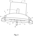
- a cover 5 of the shredding attachment is shown.
- the cover 5 comprises two shafts 6, which are formed by an upwardly projecting nozzle with an inner partition.
- the shafts 6 are adapted to the two rams 1 in such a way that the rams 1 can be inserted into the two shafts 6.
- the laterally projecting edge 2 prevents the pestles 1 from falling through the shafts 6. With the help of the pestles 1, a dish or an ingredient of a dish can be pushed through the shafts 6 against a Figure 3 shown crushing tool 14.
- the shafts 6 and the nozzle are connected at their underside to a curved cap 7, specifically in an edge area of the cap 7.
- Partially circular steps 8 are provided on two opposite sides of the underside of the cap 7. The two part-circular steps 8 project laterally and downwardly from the cap 7.
- a mandrel 9 projects upwards from the cap 7, approximately from the center of the cap 7.
- a rod 10 projecting downwards from the cap 7 is held by the mandrel 9.
- the outer diameter of the mandrel 9 is larger than the maximum outer diameter of the rod 10.
- the rod 10 can have a cylindrical thickening 11 with a tapered free end 12 at its free end.
- the underside of the steps 8 can be designed as a hook shape 13.
- a chopping tool is shown, namely a cutting disc 14 with a knife or blade 15 and further cutting means 16.
- the knife 15 and the further cutting means 16 can chop the ingredient of a dish or a dish by rotating the cutting disc 14 around its shaft 17.
- a chopped ingredient passes through the cutting disc 14.
- the shaft 17 is shaft-shaped, at least partially hollow, and has ring-shaped coupling elements 18 and 19 at its ends.
- the rod 10 can be inserted through the upper coupling element 18 into the shaft of the shaft 17. This stabilizes the position of the shaft 17 during operation in the assembled state of the chopping attachment.
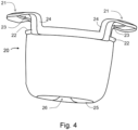
- the Figure 4 shows a container 20 of the shredding attachment.
- the two handles 21 extend from the upper edge sections 22 of the container 20, first upwards and then outwards to the side. Each handle 21 thus forms an opening 23.
- the steps 8 can be inserted into the openings 23.
- the undersides of the steps 8 then rest on the edge sections 22.
- the upward-facing webs 24 of the handles 21 then prevent the cover 5 with the cap 7 from slipping sideways. and contribute to the positioning of the cover 5.
- the hook shapes 13 of the undersides can then engage around the edge sections 22 and thus additionally contribute to the positioning of the cover 5 relative to the container 20 and to preventing lateral slipping (see also Figure 8 ).
- the bottom 25 of the container 20 has a funnel-shaped opening 26 which opens into a hollow shaft.
- a shaft 27 is shown, which can be inserted through the funnel-shaped opening 26 and the adjoining hollow shaft.
- the upper end of the shaft 27 has a coupling element 28, which can be inserted into the lower coupling element 19 of the cutting disc 13.
- the outer contour of the coupling element 28 corresponds to the inner contour of the coupling element 19. This ensures that the two coupling elements are connected to one another in a rotationally fixed manner when the coupling element 28 is inserted into the coupling element 19.
- the shaft 27 has a lower coupling element 29.
- the lower coupling element 29 can be mounted on a mixing tool inside a food preparation vessel of a food processor such that the coupling element 29 is connected to the mixing tool in a rotationally fixed manner. Rotating the mixing tool then also rotates the cutting disc 13 if the shaft 27 is connected to the cutting disc 13 in a rotationally fixed manner.
- the Figure 6 shows such a food processor 30 with a food preparation vessel 31.
- a lid part 32 is placed on the food preparation vessel 31.
- the lid part 32 for the food preparation vessel 31 is locked by arm-like locking elements, i.e. arms 33.
- the lid part 32 is located between the two arms 33.
- the arms 33 can be rotated by a motor about their longitudinal axis and thus back and forth between an open position and a locked position.
- the lid part 32 has a sensor, namely a rocker arm 34 of an electrical switch, which is pressed down and thus triggered.
- the arm-like locking elements 33 and the rocker arm 34 are attached to a base part 35 of the food processor 30.
- the food preparation vessel 31 is inserted into the base part 35 and can be removed from the base part 35.
- the base part 35 comprises a display 37 and a Rotary switch 38.
- the lid part 32 includes an opening 39 in the center, which can be closed with a container-like closure.
- the triggered rocker arm 34 informs the control unit of the food processor 30 that the lid part is properly attached and locked. However, the control unit of the food processor 30 was unable to receive information about the status of the container-like closure (not shown).
- the Figure 7 shows the kitchen machine 30 from the Figure 6 .
- the area of the food preparation vessel 31 is shown cut open so that the interior is visible.
- a rotatable mixing tool 41 At the base 40 of the food preparation vessel 31 there is a rotatable mixing tool 41.
- the mixing tool 41 is driven by a shaft 43 which extends through the base 40 of the food preparation vessel 31.
- the shaft 43 is inserted into a coupling element 42 of the base part 35 by means of a lower coupling element and is thereby connected in a rotationally fixed manner.
- the coupling element 42 is connected to the shaft of an electric motor which is located in the base part 35.
- the mixing tool 41 can be rotated via the electric motor in the base part 35.
- the coupling element 29 shown can be placed on the shaft 43 in such a way that a rotationally fixed connection is established between the mixing tool 41 and the coupling element 29.
- the chopping attachment can be placed on the food preparation vessel 31.
- the locking element 33 rests on the step 8 of the cover 5 in such a way that the cover 5 can no longer be detached from the food preparation vessel 31.
- the cover 5 rests on the upper edge 22 of the container with the handle 21. As a result, the container with the handle 21 cannot be removed from the food preparation container 31.
- the rocker lever 34 is actuated by a laterally projecting edge section 22a of the container with the handle 21.
- the cover 5 can indeed be locked even without the container enclosing the handle 21 being present.
- the rocker arm 34 is not actuated and thus not triggered.
- the control device of the food processor is configured to detect the locked state.
- the control device has the information that the rocker arm 34 has not been triggered due to the absence of the container with the handle 21. The control device therefore detects a faulty state.
- the detection of the locked state by the locking elements 33 can be carried out via a pressure sensor or, for example, via an evaluation of the power consumption of the electric motor used for locking, which must apply an increased force when locking takes place.
- the example has shown that at least two parts of a multi-part attachment can be monitored with little effort.
Landscapes
- Engineering & Computer Science (AREA)
- Mechanical Engineering (AREA)
- Food Science & Technology (AREA)
- Food-Manufacturing Devices (AREA)
Claims (13)
- Appareil de préparation d'aliments (30) avec un récipient de préparation d'aliments (31), un couvercle (32) qui peut être posé sur le récipient de préparation d'aliments (31), une pièce rapportée qui peut être posée sur le récipient de préparation d'aliments (31) à la place du couvercle (32), dans lequel la pièce rapportée comprend une première pièce (5) et une deuxième pièce (20 à 26), un dispositif de verrouillage pour un verrouillage du couvercle (32) posé sur le récipient de préparation d'aliments (31) ainsi que pour un verrouillage de la pièce rapportée posée sur le récipient de préparation d'aliments (31), un capteur (34) qui est déclenché lorsque le couvercle (32) posé est verrouillé par le dispositif de verrouillage, et qui est déclenché lorsque la pièce rapportée posée est verrouillée par le dispositif de verrouillage, dans lequel le capteur (34) n'est pas déclenché lorsque seule une pièce (5) de la pièce rapportée est posée sur le récipient de préparation d'aliments (31) et verrouillée.
- Appareil de préparation d'aliments (30) selon la revendication précédente, caractérisé en ce que le dispositif de verrouillage est constitué de telle sorte que la pièce rapportée, à l'état posé, est déplacée par le verrouillage d'une position initiale à une position finale, et le capteur (34) est déclenché lorsque la pièce rapportée se trouve dans la position finale.
- Appareil de préparation d'aliments (30) selon la revendication précédente, caractérisé en ce que le dispositif de verrouillage est constitué de telle sorte que la première pièce (5) de la pièce rapportée est déplacée par le verrouillage de la position initiale à la position finale, et la première pièce (5) est constituée de telle sorte que celle-ci déplace par le verrouillage la deuxième pièce (20 à 26) de la pièce rapportée de la position initiale à la position finale, et la deuxième pièce (20 à 26) est constituée de telle sorte que celle-ci a déclenché le capteur (34) lorsque la deuxième pièce (20 à 26) se trouve dans sa position finale.
- Appareil de préparation d'aliments (30) selon la revendication précédente, caractérisé en ce que la deuxième pièce est un récipient (20 à 26) et la première pièce est un couvercle (5) pour le récipient.
- Appareil de préparation d'aliments (30) selon la revendication précédente, caractérisé en ce que le récipient (20 à 26) présente sur sa face supérieure, au moins par sections, un bord (22, 22a) faisant saillie latéralement.
- Appareil de préparation d'aliments (30) selon la revendication précédente, caractérisé en ce que le capteur (34) peut être déclenché par le bord (22a) faisant saillie du récipient (20 à 26).
- Appareil de préparation d'aliments (30) selon l'une des trois revendications précédentes, caractérisé en ce que le récipient (20 à 26) comprend sur sa face supérieure au moins une poignée (21) faisant saillie vers le haut et/ou latéralement.
- Appareil de préparation d'aliments (30) selon l'une des quatre revendications précédentes, caractérisé en ce que la pièce rapportée comprend un outil de broyage tournable (14) pour broyer des aliments, dans lequel l'outil de broyage (14) est disposé ou peut être disposé par rapport au récipient (20 à 26) de telle sorte qu'un aliment tombe par gravité vers le bas après avoir été broyé au moyen de l'outil de broyage (14), afin d'être recueilli dans le récipient (20 à 26) de la pièce rapportée.
- Appareil de préparation d'aliments (30) selon l'une des revendications précédentes, caractérisé en ce que la pièce rapportée se trouve entre deux éléments de verrouillage (33) du dispositif de verrouillage lorsque la pièce rapportée est posée sur le récipient de préparation d'aliments (31).
- Appareil de préparation d'aliments (30) selon l'une des revendications précédentes, caractérisé en ce qu'un élément de verrouillage du dispositif de verrouillage est un bras tournable (33) autour de son axe longitudinal, qui peut être tourné d'une position d'ouverture à une position de verrouillage et inversement, dans lequel le bras tournable (33) peut être tourné de préférence par un entraînement électrique de l'appareil de préparation d'aliments (30).
- Appareil de préparation d'aliments (30) selon l'une des revendications précédentes, caractérisé en ce que le capteur est un interrupteur avec un levier basculant (34) sur lequel repose la pièce rapportée lorsque la pièce rapportée est posée sur le récipient de préparation d'aliments (31).
- Appareil de préparation d'aliments (30) selon l'une des revendications précédentes avec un outil de mélange tournable (41) pour mélanger et/ou broyer un aliment dans une zone de fond (40) du récipient de préparation d'aliments (31), avec une unité de commande avec laquelle la vitesse de rotation pour l'outil de mélange (41) peut être réglée, dans lequel une vitesse de rotation d'au moins 2000 tours par minute, de préférence d'au moins 5000 tours par minute, de manière particulièrement préférée d'au moins 8000 tours par minute, peut être réglée par l'unité de commande pour l'outil de mélange (41).
- Procédé de broyage d'un aliment en utilisant un appareil de préparation d'aliments (30) selon l'une des revendications précédentes 1 à 12, dans lequel la pièce rapportée est posée sur le récipient de préparation d'aliments (31) de l'appareil de préparation d'aliments (30), et est verrouillée après la pose, dans lequel par le verrouillage le capteur (34) est déclenché par une pièce (5) de la pièce rapportée.
Priority Applications (4)
| Application Number | Priority Date | Filing Date | Title |
|---|---|---|---|
| EP21185470.8A EP4119016B1 (fr) | 2021-07-14 | 2021-07-14 | Dispositif de préparation des aliments pourvu d'un accessoire en plusieurs parties |
| AU2022203129A AU2022203129A1 (en) | 2021-07-14 | 2022-05-10 | Food preparation appliance with multi-part attachment part |
| US17/847,844 US12329324B2 (en) | 2021-07-14 | 2022-06-23 | Food preparation appliance with multi-part attachment part |
| CN202210828484.3A CN115700099B (zh) | 2021-07-14 | 2022-07-13 | 具有多部件附件的食物制备器具 |
Applications Claiming Priority (1)
| Application Number | Priority Date | Filing Date | Title |
|---|---|---|---|
| EP21185470.8A EP4119016B1 (fr) | 2021-07-14 | 2021-07-14 | Dispositif de préparation des aliments pourvu d'un accessoire en plusieurs parties |
Publications (3)
| Publication Number | Publication Date |
|---|---|
| EP4119016A1 EP4119016A1 (fr) | 2023-01-18 |
| EP4119016B1 true EP4119016B1 (fr) | 2025-06-18 |
| EP4119016C0 EP4119016C0 (fr) | 2025-06-18 |
Family
ID=76920643
Family Applications (1)
| Application Number | Title | Priority Date | Filing Date |
|---|---|---|---|
| EP21185470.8A Active EP4119016B1 (fr) | 2021-07-14 | 2021-07-14 | Dispositif de préparation des aliments pourvu d'un accessoire en plusieurs parties |
Country Status (4)
| Country | Link |
|---|---|
| US (1) | US12329324B2 (fr) |
| EP (1) | EP4119016B1 (fr) |
| CN (1) | CN115700099B (fr) |
| AU (1) | AU2022203129A1 (fr) |
Families Citing this family (1)
| Publication number | Priority date | Publication date | Assignee | Title |
|---|---|---|---|---|
| EP4588409A1 (fr) | 2024-01-17 | 2025-07-23 | Vorwerk & Co. Interholding GmbH | Appareil de cuisine avec coupe-spirale |
Citations (1)
| Publication number | Priority date | Publication date | Assignee | Title |
|---|---|---|---|---|
| US9775467B2 (en) * | 2013-10-07 | 2017-10-03 | Capbran Holdings, Llc | Blender |
Family Cites Families (20)
| Publication number | Priority date | Publication date | Assignee | Title |
|---|---|---|---|---|
| US4194697A (en) * | 1979-01-22 | 1980-03-25 | William Lembeck | Food processor and auxiliary mixing bowl therefor |
| US4523720A (en) * | 1982-01-15 | 1985-06-18 | Robot-Coupe, S.A. | Food processor assembly |
| US5921485A (en) * | 1998-04-10 | 1999-07-13 | Hp Intellectual Corp. | Food processor |
| US6907819B2 (en) * | 2003-07-01 | 2005-06-21 | Conair Corporation | Flip ramp mechanical interlock for appliance |
| US7028930B2 (en) * | 2004-02-19 | 2006-04-18 | Hamilton Beach/Proctor-Silex, Inc. | Kitchen appliance with a safety interlock |
| CN101554292B (zh) * | 2009-05-30 | 2011-11-16 | 周文乾 | 饮用水调温装置及由其构成的饮用水设备 |
| JP5298353B2 (ja) * | 2009-09-17 | 2013-09-25 | 日本クロージャー株式会社 | 合成樹脂製蓋及びかかる蓋と容器本体とから構成された容器 |
| US8584979B2 (en) * | 2010-10-08 | 2013-11-19 | Hamilton Beach Brands, Inc. | Food processor with multiple processing containers |
| FR2993157B1 (fr) * | 2012-07-16 | 2016-07-01 | Seb Sa | Appareil de cuisson d'aliments sous pression a dispositif de commande ameliore |
| DE102013012192A1 (de) * | 2012-08-16 | 2014-03-13 | Vorwerk & Co. Interholding Gmbh | Elektrisch betriebene Küchenmaschine |
| DE102014111193A1 (de) | 2014-08-06 | 2016-02-11 | Vorwerk & Co. Interholding Gmbh | Küchenmaschine mit einer Wägeeinrichtung |
| DE102014119315A1 (de) * | 2014-12-22 | 2016-06-23 | Vorwerk & Co. Interholding Gmbh | Küchenmaschine, insbesondere Mixgerät |
| GB2547683B (en) * | 2016-02-25 | 2022-07-13 | Kenwood Ltd | Kitchen appliance |
| KR101829240B1 (ko) * | 2016-12-27 | 2018-02-14 | 주식회사 신영트레이딩 | 다기능 가열 조리기 |
| EP3420864B1 (fr) * | 2017-06-29 | 2020-09-16 | Vorwerk & Co. Interholding GmbH | Robot ménager avec une coupe de mesure comprenant capteurs pour déterminer un état de fonctionnement |
| DE102017121946A1 (de) | 2017-09-21 | 2019-03-21 | Vorwerk & Co. Interholding Gmbh | Elektromotorisch betriebene Küchenmaschine |
| PL3578089T3 (pl) * | 2018-06-06 | 2022-06-13 | Vorwerk & Co. Interholding Gmbh | Urządzenie czyszczące do naczynia mieszającego urządzenia kuchennego napędzanego elektromotorycznie |
| CN110313854B (zh) * | 2019-08-23 | 2021-10-26 | 莱克电气股份有限公司 | 一种料理机 |
| GB2591228B (en) * | 2020-01-07 | 2024-02-28 | Kenwood Ltd | Kitchen appliance, container, assembly and drive shaft extension therefor, and kits of parts |
| EP4087458A1 (fr) * | 2020-01-07 | 2022-11-16 | Kenwood Limited | Appareil de cuisine, récipient, ensemble et extension d'arbre d'entraînement pour celui-ci, et trousses de pièces |
-
2021
- 2021-07-14 EP EP21185470.8A patent/EP4119016B1/fr active Active
-
2022
- 2022-05-10 AU AU2022203129A patent/AU2022203129A1/en active Pending
- 2022-06-23 US US17/847,844 patent/US12329324B2/en active Active
- 2022-07-13 CN CN202210828484.3A patent/CN115700099B/zh active Active
Patent Citations (1)
| Publication number | Priority date | Publication date | Assignee | Title |
|---|---|---|---|---|
| US9775467B2 (en) * | 2013-10-07 | 2017-10-03 | Capbran Holdings, Llc | Blender |
Also Published As
| Publication number | Publication date |
|---|---|
| CN115700099A (zh) | 2023-02-07 |
| CN115700099B (zh) | 2026-02-03 |
| AU2022203129A1 (en) | 2023-02-02 |
| US12329324B2 (en) | 2025-06-17 |
| EP4119016C0 (fr) | 2025-06-18 |
| US20230018278A1 (en) | 2023-01-19 |
| EP4119016A1 (fr) | 2023-01-18 |
Similar Documents
| Publication | Publication Date | Title |
|---|---|---|
| EP2015660B1 (fr) | Dispositif de traitement d'aliments | |
| EP4026460B1 (fr) | Appareil de préparation des aliments permettant de couper les aliments, pièce rapportée de broyage et procédé | |
| DE69916084T2 (de) | Lösbarer werkzeugträger zum zubereiten von nahrungsmitteln für mischgeräte, küchenmaschinen, zerkleinerungsgeräten und ähnlichen geräten | |
| DE69720265T2 (de) | Pressvorrichtung für nahrungsmittel, wie früchte oder gemüse, und küchengerät mit einer solchen pressvorrichtung | |
| DE2141813A1 (de) | Geraet fuer die zubereitung von nahrungsmitteln | |
| EP3513696B1 (fr) | Robot de cuisine avec un élement de couverture pour un récipient de préparation | |
| EP2978349B1 (fr) | Accessoire de préparation avec protection contre les manipulations | |
| EP4098155B1 (fr) | Insert d'extraction de jus pour un récipient de préparation, ainsi que robot de cuisine pourvu d'insert d'extraction de jus | |
| EP4119016B1 (fr) | Dispositif de préparation des aliments pourvu d'un accessoire en plusieurs parties | |
| EP3936014B1 (fr) | Appareil de préparation des aliments permettant de couper les aliments, pièce rapportée de broyage et procédé | |
| DE102015109402A1 (de) | Vorrichtung zum Zerkleinern von Lebensmitteln | |
| DE202021105193U1 (de) | Küchenmaschine und Häckslerergänzungsset für eine Küchenmaschine | |
| DE202022002722U1 (de) | Küchenmaschinenanordnung und Zerkleinerungsbaugruppe für eine Küchenmaschine | |
| DE3627276A1 (de) | Schneideinsatz fuer einen arbeitsbehaelter einer kuechenmaschine | |
| DE3530651C2 (de) | Elektrisch betriebenes Gerät für die Bearbeitung und Zubereitung von Nahrungsmitteln aller Art | |
| EP4588409A1 (fr) | Appareil de cuisine avec coupe-spirale | |
| DE102021124947A1 (de) | Ergänzungsset für ein Multifunktionsküchengerät, ein Multifunktionsküchengerät und ein Verfahren zum Bearbeiten von Schneidgut | |
| DE102021124950A1 (de) | Küchenmaschine und Häckslerergänzungsset für eine Küchenmaschine | |
| DE4242289C2 (de) | Universal-Küchenmaschine für den Haushalt | |
| DE3837961C2 (de) | Küchenmaschine mit aufsetzbarem Elektro-Handquirl als Antrieb | |
| EP4287917B1 (fr) | Agencement de robot culinaire | |
| DE4322280A1 (de) | Arbeitsbehälter für eine elektrisch betriebene Haushaltsküchenmaschine | |
| EP3185733B1 (fr) | Récipient de préparation muni d'un couvercle et d'un raccordement de sécurité | |
| EP4119019A1 (fr) | Dispositif de coupe pour un broyage des denrées alimentaires et appareil de préparation des aliments | |
| WO2025056187A1 (fr) | Robot de cuisine |
Legal Events
| Date | Code | Title | Description |
|---|---|---|---|
| PUAI | Public reference made under article 153(3) epc to a published international application that has entered the european phase |
Free format text: ORIGINAL CODE: 0009012 |
|
| STAA | Information on the status of an ep patent application or granted ep patent |
Free format text: STATUS: THE APPLICATION HAS BEEN PUBLISHED |
|
| AK | Designated contracting states |
Kind code of ref document: A1 Designated state(s): AL AT BE BG CH CY CZ DE DK EE ES FI FR GB GR HR HU IE IS IT LI LT LU LV MC MK MT NL NO PL PT RO RS SE SI SK SM TR |
|
| STAA | Information on the status of an ep patent application or granted ep patent |
Free format text: STATUS: REQUEST FOR EXAMINATION WAS MADE |
|
| 17P | Request for examination filed |
Effective date: 20230309 |
|
| RBV | Designated contracting states (corrected) |
Designated state(s): AL AT BE BG CH CY CZ DE DK EE ES FI FR GB GR HR HU IE IS IT LI LT LU LV MC MK MT NL NO PL PT RO RS SE SI SK SM TR |
|
| STAA | Information on the status of an ep patent application or granted ep patent |
Free format text: STATUS: EXAMINATION IS IN PROGRESS |
|
| 17Q | First examination report despatched |
Effective date: 20231220 |
|
| GRAP | Despatch of communication of intention to grant a patent |
Free format text: ORIGINAL CODE: EPIDOSNIGR1 |
|
| STAA | Information on the status of an ep patent application or granted ep patent |
Free format text: STATUS: GRANT OF PATENT IS INTENDED |
|
| INTG | Intention to grant announced |
Effective date: 20241112 |
|
| RAP3 | Party data changed (applicant data changed or rights of an application transferred) |
Owner name: VORWERK & CO. INTERHOLDING GMBH |
|
| GRAJ | Information related to disapproval of communication of intention to grant by the applicant or resumption of examination proceedings by the epo deleted |
Free format text: ORIGINAL CODE: EPIDOSDIGR1 |
|
| STAA | Information on the status of an ep patent application or granted ep patent |
Free format text: STATUS: EXAMINATION IS IN PROGRESS |
|
| GRAP | Despatch of communication of intention to grant a patent |
Free format text: ORIGINAL CODE: EPIDOSNIGR1 |
|
| STAA | Information on the status of an ep patent application or granted ep patent |
Free format text: STATUS: GRANT OF PATENT IS INTENDED |
|
| INTC | Intention to grant announced (deleted) | ||
| INTG | Intention to grant announced |
Effective date: 20250303 |
|
| GRAS | Grant fee paid |
Free format text: ORIGINAL CODE: EPIDOSNIGR3 |
|
| GRAA | (expected) grant |
Free format text: ORIGINAL CODE: 0009210 |
|
| STAA | Information on the status of an ep patent application or granted ep patent |
Free format text: STATUS: THE PATENT HAS BEEN GRANTED |
|
| AK | Designated contracting states |
Kind code of ref document: B1 Designated state(s): AL AT BE BG CH CY CZ DE DK EE ES FI FR GB GR HR HU IE IS IT LI LT LU LV MC MK MT NL NO PL PT RO RS SE SI SK SM TR |
|
| REG | Reference to a national code |
Ref country code: GB Ref legal event code: FG4D Free format text: NOT ENGLISH |
|
| REG | Reference to a national code |
Ref country code: CH Ref legal event code: EP |
|
| REG | Reference to a national code |
Ref country code: DE Ref legal event code: R096 Ref document number: 502021007755 Country of ref document: DE |
|
| REG | Reference to a national code |
Ref country code: CH Ref legal event code: EP |
|
| REG | Reference to a national code |
Ref country code: IE Ref legal event code: FG4D Free format text: LANGUAGE OF EP DOCUMENT: GERMAN |
|
| U01 | Request for unitary effect filed |
Effective date: 20250704 |
|
| U07 | Unitary effect registered |
Designated state(s): AT BE BG DE DK EE FI FR IT LT LU LV MT NL PT RO SE SI Effective date: 20250711 |
|
| PG25 | Lapsed in a contracting state [announced via postgrant information from national office to epo] |
Ref country code: NO Free format text: LAPSE BECAUSE OF FAILURE TO SUBMIT A TRANSLATION OF THE DESCRIPTION OR TO PAY THE FEE WITHIN THE PRESCRIBED TIME-LIMIT Effective date: 20250918 Ref country code: GR Free format text: LAPSE BECAUSE OF FAILURE TO SUBMIT A TRANSLATION OF THE DESCRIPTION OR TO PAY THE FEE WITHIN THE PRESCRIBED TIME-LIMIT Effective date: 20250919 |
|
| PG25 | Lapsed in a contracting state [announced via postgrant information from national office to epo] |
Ref country code: HR Free format text: LAPSE BECAUSE OF FAILURE TO SUBMIT A TRANSLATION OF THE DESCRIPTION OR TO PAY THE FEE WITHIN THE PRESCRIBED TIME-LIMIT Effective date: 20250618 |
|
| PG25 | Lapsed in a contracting state [announced via postgrant information from national office to epo] |
Ref country code: RS Free format text: LAPSE BECAUSE OF FAILURE TO SUBMIT A TRANSLATION OF THE DESCRIPTION OR TO PAY THE FEE WITHIN THE PRESCRIBED TIME-LIMIT Effective date: 20250918 |
|
| U20 | Renewal fee for the european patent with unitary effect paid |
Year of fee payment: 5 Effective date: 20251001 |
|
| PG25 | Lapsed in a contracting state [announced via postgrant information from national office to epo] |
Ref country code: IS Free format text: LAPSE BECAUSE OF FAILURE TO SUBMIT A TRANSLATION OF THE DESCRIPTION OR TO PAY THE FEE WITHIN THE PRESCRIBED TIME-LIMIT Effective date: 20251018 |
|
| PG25 | Lapsed in a contracting state [announced via postgrant information from national office to epo] |
Ref country code: SM Free format text: LAPSE BECAUSE OF FAILURE TO SUBMIT A TRANSLATION OF THE DESCRIPTION OR TO PAY THE FEE WITHIN THE PRESCRIBED TIME-LIMIT Effective date: 20250618 |
|
| PG25 | Lapsed in a contracting state [announced via postgrant information from national office to epo] |
Ref country code: CZ Free format text: LAPSE BECAUSE OF FAILURE TO SUBMIT A TRANSLATION OF THE DESCRIPTION OR TO PAY THE FEE WITHIN THE PRESCRIBED TIME-LIMIT Effective date: 20250618 |
|
| PG25 | Lapsed in a contracting state [announced via postgrant information from national office to epo] |
Ref country code: PL Free format text: LAPSE BECAUSE OF FAILURE TO SUBMIT A TRANSLATION OF THE DESCRIPTION OR TO PAY THE FEE WITHIN THE PRESCRIBED TIME-LIMIT Effective date: 20250618 |
|
| PG25 | Lapsed in a contracting state [announced via postgrant information from national office to epo] |
Ref country code: SK Free format text: LAPSE BECAUSE OF FAILURE TO SUBMIT A TRANSLATION OF THE DESCRIPTION OR TO PAY THE FEE WITHIN THE PRESCRIBED TIME-LIMIT Effective date: 20250618 |
|
| PG25 | Lapsed in a contracting state [announced via postgrant information from national office to epo] |
Ref country code: ES Free format text: LAPSE BECAUSE OF FAILURE TO SUBMIT A TRANSLATION OF THE DESCRIPTION OR TO PAY THE FEE WITHIN THE PRESCRIBED TIME-LIMIT Effective date: 20250618 |
|
| REG | Reference to a national code |
Ref country code: CH Ref legal event code: H13 Free format text: ST27 STATUS EVENT CODE: U-0-0-H10-H13 (AS PROVIDED BY THE NATIONAL OFFICE) Effective date: 20260224 |
|
| PG25 | Lapsed in a contracting state [announced via postgrant information from national office to epo] |
Ref country code: MC Free format text: LAPSE BECAUSE OF FAILURE TO SUBMIT A TRANSLATION OF THE DESCRIPTION OR TO PAY THE FEE WITHIN THE PRESCRIBED TIME-LIMIT Effective date: 20250618 |
|
| PG25 | Lapsed in a contracting state [announced via postgrant information from national office to epo] |
Ref country code: CH Free format text: LAPSE BECAUSE OF NON-PAYMENT OF DUE FEES Effective date: 20250731 |
|
| PLBE | No opposition filed within time limit |
Free format text: ORIGINAL CODE: 0009261 |
|
| STAA | Information on the status of an ep patent application or granted ep patent |
Free format text: STATUS: NO OPPOSITION FILED WITHIN TIME LIMIT |
|
| REG | Reference to a national code |
Ref country code: CH Ref legal event code: L10 Free format text: ST27 STATUS EVENT CODE: U-0-0-L10-L00 (AS PROVIDED BY THE NATIONAL OFFICE) Effective date: 20260430 |