EP4119040B1 - Vorrichtung und verfahren zur charakterisierung des rauheitsprofils einer gewebeprobe - Google Patents
Vorrichtung und verfahren zur charakterisierung des rauheitsprofils einer gewebeprobe Download PDFInfo
- Publication number
- EP4119040B1 EP4119040B1 EP21767619.6A EP21767619A EP4119040B1 EP 4119040 B1 EP4119040 B1 EP 4119040B1 EP 21767619 A EP21767619 A EP 21767619A EP 4119040 B1 EP4119040 B1 EP 4119040B1
- Authority
- EP
- European Patent Office
- Prior art keywords
- laser beam
- half wave
- glass plate
- ground glass
- wave blade
- Prior art date
- Legal status (The legal status is an assumption and is not a legal conclusion. Google has not performed a legal analysis and makes no representation as to the accuracy of the status listed.)
- Active
Links
Images


Classifications
-
- A—HUMAN NECESSITIES
- A61—MEDICAL OR VETERINARY SCIENCE; HYGIENE
- A61B—DIAGNOSIS; SURGERY; IDENTIFICATION
- A61B5/00—Measuring for diagnostic purposes; Identification of persons
- A61B5/0059—Measuring for diagnostic purposes; Identification of persons using light, e.g. diagnosis by transillumination, diascopy, fluorescence
-
- G—PHYSICS
- G01—MEASURING; TESTING
- G01B—MEASURING LENGTH, THICKNESS OR SIMILAR LINEAR DIMENSIONS; MEASURING ANGLES; MEASURING AREAS; MEASURING IRREGULARITIES OF SURFACES OR CONTOURS
- G01B11/00—Measuring arrangements characterised by the use of optical techniques
- G01B11/30—Measuring arrangements characterised by the use of optical techniques for measuring roughness or irregularity of surfaces
-
- G—PHYSICS
- G01—MEASURING; TESTING
- G01B—MEASURING LENGTH, THICKNESS OR SIMILAR LINEAR DIMENSIONS; MEASURING ANGLES; MEASURING AREAS; MEASURING IRREGULARITIES OF SURFACES OR CONTOURS
- G01B11/00—Measuring arrangements characterised by the use of optical techniques
- G01B11/30—Measuring arrangements characterised by the use of optical techniques for measuring roughness or irregularity of surfaces
- G01B11/303—Measuring arrangements characterised by the use of optical techniques for measuring roughness or irregularity of surfaces using photoelectric detection means
-
- G—PHYSICS
- G01—MEASURING; TESTING
- G01B—MEASURING LENGTH, THICKNESS OR SIMILAR LINEAR DIMENSIONS; MEASURING ANGLES; MEASURING AREAS; MEASURING IRREGULARITIES OF SURFACES OR CONTOURS
- G01B9/00—Measuring instruments characterised by the use of optical techniques
- G01B9/02—Interferometers
- G01B9/02094—Speckle interferometers, i.e. for detecting changes in speckle pattern
-
- G—PHYSICS
- G01—MEASURING; TESTING
- G01N—INVESTIGATING OR ANALYSING MATERIALS BY DETERMINING THEIR CHEMICAL OR PHYSICAL PROPERTIES
- G01N21/00—Investigating or analysing materials by the use of optical means, i.e. using sub-millimetre waves, infrared, visible or ultraviolet light
- G01N21/17—Systems in which incident light is modified in accordance with the properties of the material investigated
- G01N21/21—Polarisation-affecting properties
-
- A—HUMAN NECESSITIES
- A61—MEDICAL OR VETERINARY SCIENCE; HYGIENE
- A61B—DIAGNOSIS; SURGERY; IDENTIFICATION
- A61B5/00—Measuring for diagnostic purposes; Identification of persons
-
- G—PHYSICS
- G01—MEASURING; TESTING
- G01N—INVESTIGATING OR ANALYSING MATERIALS BY DETERMINING THEIR CHEMICAL OR PHYSICAL PROPERTIES
- G01N21/00—Investigating or analysing materials by the use of optical means, i.e. using sub-millimetre waves, infrared, visible or ultraviolet light
- G01N21/17—Systems in which incident light is modified in accordance with the properties of the material investigated
- G01N21/21—Polarisation-affecting properties
- G01N2021/217—Measuring depolarisation or comparing polarised and depolarised parts of light
-
- G—PHYSICS
- G01—MEASURING; TESTING
- G01N—INVESTIGATING OR ANALYSING MATERIALS BY DETERMINING THEIR CHEMICAL OR PHYSICAL PROPERTIES
- G01N33/00—Investigating or analysing materials by specific methods not covered by groups G01N1/00 - G01N31/00
- G01N33/48—Biological material, e.g. blood, urine; Haemocytometers
- G01N33/483—Physical analysis of biological material
- G01N33/4833—Physical analysis of biological material of solid biological material, e.g. tissue samples, cell cultures
-
- G—PHYSICS
- G01—MEASURING; TESTING
- G01P—MEASURING LINEAR OR ANGULAR SPEED, ACCELERATION, DECELERATION, OR SHOCK; INDICATING PRESENCE, ABSENCE, OR DIRECTION, OF MOVEMENT
- G01P5/00—Measuring speed of fluids, e.g. of air stream; Measuring speed of bodies relative to fluids, e.g. of ship, of aircraft
- G01P5/26—Measuring speed of fluids, e.g. of air stream; Measuring speed of bodies relative to fluids, e.g. of ship, of aircraft by measuring the direct influence of the streaming fluid on the properties of a detecting optical wave
Definitions
- the invention generally belongs to the field of optics, and more particularly to the field of microscopy.
- a first object of the present invention is a device designed to obtain useful information for the characterization of rough tissue samples.
- a second object of the invention is a procedure carried out by said device to determine the degree of anisotropy of the sample through depolarization correlation measurements.
- a third object of the invention is a procedure carried out by said device to determine the roughness frequency of the sample through speckle interferometry correlation measurements.
- a fourth object of the invention is a procedure carried out by said device to determine the average speed of the dispersive components of the tissue through temporal correlation measurements.
- a biological tissue can be defined as a natural biological material made up of a complex and organized set of cells regularly distributed and endowed with a coordinated physiological behavior.
- a biopsy procedure basically consists of the removal of a sample of the target tissue and the subsequent exhaustive study of the sample under a microscope by a pathologist. The results of this study are communicated to the doctor for evaluation and subsequent communication to the patient.
- This method has the drawback that it requires a large amount of time, since the pathologist must carry out an individualized manual study of each of the samples to be studied.
- the high specificity of the training required to carry out the study of the sample under the microscope restricts the number of professionals suitable for this work. As a consequence, a waiting list is frequently generated in which the average time for the doctor to receive the results can be several weeks.
- US 2007/146632 A1 describes a method and an apparatus utilizing actively illuminated imaging polarimetry for identifying a feature or features in an object through evaluation of how the object scrambles different incident fully polarized states into partially polarized states. It may be used for retinal imaging, liquid crystal testing, active remote sensing, and other applications.
- the present invention solves the previous problem through the use of a new device attachable to a microscope that allows obtaining different types of measurements based on the light scattered in reflection, or light backscattered, by the tissue in response to its illumination by a laser source.
- the light scattered by reflection obtained through the microscope can be analyzed automatically using a suitable processing means, so that the final result is representative parameters of the surface of the tissue.
- the values of these parameters allow us to infer a large amount of useful information for the pathological diagnosis of the tissue sample in question.
- this new device is applicable to the analysis of biological tissue samples, such as samples obtained from a biopsy or the like, or even biological tissues in vivo.
- biological tissue samples such as samples obtained from a biopsy or the like
- its application is not limited to biological tissues, but can be used in a general way for the characterization of any rough surface.
- a first aspect of the invention is directed to a device for characterizing the rough profile of a tissue sample, which basically comprises the following elements: a laser source, a photodetector, and a displacement means. Each of these elements is described in more detail below:
- This novel device thus allows carrying out the aforementioned surface characterization procedures, since it allows selectively inserting the ground glass plate or the half wave blade in the path of the laser beam, as well as selectively rotating each of these elements depending on the position.
- the device further comprises optical light conducting means which conduct the laser beam from the laser source towards the surface of the tissue and the light scattered in reflection by the surface of the tissue towards the photodetector.
- optical light conducting means which conduct the laser beam from the laser source towards the surface of the tissue and the light scattered in reflection by the surface of the tissue towards the photodetector.
- the light conducting means comprises mirrors, lenses and beam splitters.
- This configuration is especially suitable for the implementation of the device of the invention in a microscope, as it allows the insertion within the same optical path of other light signals such as a white light to illuminate the field of view, as well as the extraction of said optical path of light signals of interest.
- the optical light conducting means comprises an optical fiber housed in an endoscope. This configuration is especially suitable for use of the device in in vivo tissue analysis.
- the analysis of the signals received by the photodetector to calculate the representative parameters of the surface of the tissue can be performed by a suitable external processing means.
- the data obtained by the photodetector can be transmitted to a computer, tablet, smartphone, or any other similar device wherein dedicated software obtains said parameters.
- the device itself comprises a processing means that receives the signal obtained by the photodetector in response to the light reflected in received dispersion and calculates said useful parameters for characterizing the rough profile of the surface.
- the device is attached to a microscope.
- a plate containing all the elements of the present device can be attached to a microscope in such a way that the laser beam, once it has passed the displacement means, is inserted into the optical path that passes through the objective of said microscope.
- a second aspect of the present invention is directed to a procedure of determining surface roughness frequency using the above device.
- the ground glass plate is interposed in the path of the laser beam at the same time it rotates, so that the angle of illumination on the sample changes without the need to modify the position of the laser source.
- the value of the correlation will be related to the roughness of the surface.
- the correlation will hold, even for large angles of rotation.
- rougher surfaces will lose the correlation, even for small angles of rotation.
- Surface roughness can be indicative of changes in cell arrangement and tissue hydration, which may be indicative of some pathology or abnormal development of a tissue area.
- the procedure to obtain the roughness frequency of the sample surface comprises the following steps:
- a third aspect of the invention is directed to a procedure for determining the degree of depolarization of the surface using the above device.
- the half wave blade is interposed in the path of the laser beam at the same time that it rotates.
- the electromagnetic field of the emitted laser beam rotates depending on the angle of rotation of the half wave blade, thus rotating its plane of polarization.
- This allows analysis of the polarization anisotropy of the sample.
- measurements are taken for a complete rotation of the half wave blade and, then the autocorrelation of the measured intensity as a function of the angle of rotation of the half wave blade is calculated.
- the degree of depolarization finally obtained represents a measure of the polarization anisotropy of the sample.
- Certain tissues such as muscle, have a high anisotropy. In these cases, part of the backscattered light maintains a direct relationship with the polarization of the incident beam. Changes in the cellular configuration of the sample, such as due to abnormal tissue growth, can thus be reflected in the value of the degree of depolarization obtained.
- the procedure to obtain the degree of depolarization of the sample surface comprises the following steps:
- a fourth aspect of the invention is directed to a procedure for determining the average speed of tissue dispersive components using the device of the invention.
- the laser beam that reaches the surface of the sample must have characteristics that are invariant over time, so that neither the rotating ground glass plate nor the rotating half wave blade are placed in the path of the laser beam, or, in any case, the half wave blade in a fixed non-rotating position.
- the measurements thus obtained are temporal correlation measurements that allow in-vivo dynamic information to be obtained. To do this, the temporal autocorrelation of the light intensity measured as a function of time is performed to then obtain the parameter that measures the speed of the dispersive components of the tissue. This speed will allow inferring information about aspects such as cell motility or blood flow.
- the measurement of these parameters will allow the creation of multidimensional maps of the dispersion of the analyzed tissue sample that will provide a large amount of information on its morphological and dynamic characteristics that will be useful for various applications.
- FIG. 1 shows a simplified diagram of the device (1) of the present invention wherein the most important components have been represented.
- a laser source (2) which in this example is a 635 nm continuous wave laser, emits a laser beam directed towards the surface (100) of the tissue to be studied.
- a displacement means (4) is interposed that has at least one ground glass plate (5) and a half wave blade (6).
- the displacement means (4) can alternate between a first position wherein the laser beam passes through the ground glass plate (5), a second position wherein the laser beam passes through the half wave blade (6), and a third position wherein the laser beam does not pass through any of the two. That is, in the third position, the laser beam is not affected by its passage through the displacement means (4).
- the laser beam continues its path, passing through a beam splitter (71) until it falls on the surface (100).
- the reflected light is diffuse due to the scattering phenomenon produced in the light wave due to the roughness of the sample.
- light is reflected according to multiple angles instead of just one.
- Part of this scattered light in reflection hits the beam splitter (71) again and is directed towards a photodetector (3).
- the signal from the photodetector (3) is subsequently directed towards a processing means (not shown in the figures), wherein it is analyzed according to the procedures described previously in this document.
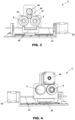
- the displacement means (4) comprises a guide (41) that takes the form of a threaded cylindrical rod arranged essentially perpendicularly in front of the laser source (2).
- a frame (42) is slidably coupled to the guide (41) so that it can slide along it from one end to the other.
- the frame (42) has two aligned holes through which the guide (41) passes.
- a translation motor (43) coupled to one end of the guide (41) causes rotation in one direction or another.
- a body to which two gears are rotatably fixed On the frame (42) there is arranged a body to which two gears are rotatably fixed: a first toothed wheel (51) provided with a central hole in which a ground glass (5) is fixed; and a second toothed wheel (61) provided with a central hole in which a half wave blade (6) is fixed.
- a first toothed wheel (51) provided with a central hole in which a ground glass (5) is fixed
- a second toothed wheel (61) provided with a central hole in which a half wave blade (6) is fixed.
- this displacement means (4) is as follows. Depending on the analysis procedure of the surface (100) to be carried out, the ground glass plate (5), the half wave blade (6), or neither of the two, is arranged in the path of the laser beam towards the surface (100). To do this, the translation motor (43) is activated until the desired element is placed in front of the laser source (2). Next, or at the same time, if necessary, the rotation motor (44) is activated to cause the rotation of the ground glass plate (5) or the half wave blade (6).
- Fig. 5 shows an example of a system (1) according to the present invention that can be configured for use in combination with a microscope (200).
- the displacement means (4) is arranged according to the first position, that is, with the ground glass plate (5) arranged in front of the laser source (2), and with a rotation motor (44) working.
- the laser beam passes through the rotating ground glass plate (5).
- the laser beam then passes through a beam splitter (71) and onto a dichroic filter (72) that reflects wavelengths above 620nm and transmits wavelengths between 400nm and 620nm.
- the 635nm laser beam is therefore reflected by the dichroic filter (72) and continues to a second beam splitter (73), which reflects it and sends it to a mirror (75), which finally orients it in parallel to the microscope objective (200).
- the laser beam falls on the surface (100), and the backscattered light follows the reverse path, passing through the mirror (75) and the beam splitter (73) and the dichroic filter (72) until it reaches the beam splitter (71), which reflects it towards the photodetector (3).
- the analysis of the light intensity received by the photodetector (3) is carried out to obtain the described parameters.
- the system shown in Fig. 5 further includes a series of additional elements, such as a spectrometer (11), a white light source (12) and collimators (13, 14). These elements are related to a series of measurements that are carried out in this system outside the object of the present invention, and therefore their operation is not described in detail here.
- a spectrometer 11
- a white light source (12)
- collimators 13, 14
- Fig. 6 shows another example of a system (1) according to the present invention, although in this case designed for use with an optical fiber (87).
- This configuration would be useful, for example, by arranging the optical fiber in an endoscope, which would allow the analysis of surfaces located inside a patient in-vivo.
- the displacement means (4) is also arranged in the first position, that is, with the ground glass plate (5) arranged in front of the laser source (2), and with the rotation motor (44) in operation.
- the laser beam thus passes through the beam splitter (81) and reaches a dichroic filter (82) that reflects wavelengths above 620nm and transmits wavelengths between 400nm and 620nm.
- the laser beam is thus directed into an optical fiber (87) that will take it to the study surface (100) inside the patient.
- the light backscattered by the surface (100) will return along the same path until it reaches the beam splitter (81), which in this case will reflect it, directing it towards the photodetector (3).
- the analysis of the light intensity received by the photodetector (3) is carried out to obtain the described parameters.
- This system (1) further includes, as in the previous case, a spectrometer (11) and a collimator (14), used to carry out measurements outside the object of the present invention.
- the speckle interferometry correlation measurements are made by making the laser beam pass through the ground glass (5) at the same time that it rotates, which will cause changes in the lighting pattern on the sample.
- the light intensity data backscattered by the sample is collected by the photodetector (3) and analyzed by the processing means so that the correlation of the light reflected by the sample when illuminated by the different patterns produced by the rotating glass is obtained.
- This correlation is related to the roughness of the surface: on very smooth surfaces the correlation will hold even for large angles of rotation, while on very rough surfaces the correlation will be lost even for small angles of rotation.
- the correlation is calculated according to the following equation, wherein ⁇ represents the angle of rotation of the ground glass and I( ⁇ ) is the light intensity received by the photodetector.
- the degree of roughness is calculated by adjusting -ln ( C roughness ( ⁇ )) as a function of the angle ⁇ , the slope of which is inversely related to the rate of variation of surface roughness.
- the parameter finally obtained is the "roughness frequency" ( ⁇ ⁇ ). ⁇ ⁇ ⁇ 1 ⁇ ⁇ l n C roughness ⁇ ⁇
- the depolarization correlation measurements are made by making the laser beam pass through the half wave blade (6) at the same time that it rotates. In this way, the incident electromagnetic field is rotated to later compare it with other previous positions of the half wave blade. This measurement offers very useful information on the degree of anisotropy of the tissue, since it compares the different states of polarization of the transmitted and reflected beam. Measurements are taken angularly for one full rotation of the half wave blade. Once performed, the autocorrelation of the measured intensity is calculated as a function of the angle of rotation ( ⁇ ) of the half wave blade (6).
- the optical fiber used will be multimode, which implies that the polarization can vary uncontrollably when crossing the fiber. However, this variation will have the same autocorrelation when rotating the incident polarization. Therefore, these measurements are not equivalent to the polarization measurements that have typically been made with single-mode fibers with maintained polarization, although equivalent quantitative results are obtained when performing autocorrelation.
- Temporal correlation measurements are made by ensuring that the laser beam that reaches the surface of the tissue has optical characteristics that are invariant over time.
- a first possibility consists of moving both the ground glass plate (5) and the half wave blade (6) out of the path of the laser beam.
- Temporal correlation measurements allow in-vivo dynamic information to be obtained, such as cell motility and blood flow. For this, the temporal autocorrelation of the intensity ( l ) measured as a function of time ( t ) is performed.
- the joint measurement of the parameters measured thanks to the device (1) of the present invention will allow the creation of multidimensional maps of the dispersion of the analyzed tissue sample that will provide a large amount of information on its morphological and dynamic characteristics in the face of various applications.
Landscapes
- Physics & Mathematics (AREA)
- Health & Medical Sciences (AREA)
- Life Sciences & Earth Sciences (AREA)
- General Physics & Mathematics (AREA)
- General Health & Medical Sciences (AREA)
- Pathology (AREA)
- Molecular Biology (AREA)
- Biophysics (AREA)
- Heart & Thoracic Surgery (AREA)
- Medical Informatics (AREA)
- Engineering & Computer Science (AREA)
- Surgery (AREA)
- Animal Behavior & Ethology (AREA)
- Biomedical Technology (AREA)
- Public Health (AREA)
- Veterinary Medicine (AREA)
- Chemical & Material Sciences (AREA)
- Analytical Chemistry (AREA)
- Biochemistry (AREA)
- Immunology (AREA)
- Investigating Or Analysing Materials By Optical Means (AREA)
Claims (12)
- Vorrichtung (1) zur Charakterisierung des Rauheitsprofils einer Gewebeprobe, aufweisend:- eine Laserquelle (2), die die Oberfläche (100) des Gewebes mit einem Dauerstrichlaserstrahl beleuchtet; und- einen Photodetektor (3), der das Licht empfängt, gestreut in Reflexion durch die Oberfläche (100) des Gewebes beleuchtet durch den Laserstrahl (2);dadurch gekennzeichnet, dass sie ferner aufweist- ein Verschiebemittel (4), das dazu eingerichtet ist, zu alternieren zwischen:einer ersten Position, in der eine rotierende Mattscheibe (5) in dem Strahlengang des Laserstrahls hin zu der Oberfläche (100) angeordnet ist;einer zweiten Position, in der eine rotierende Halbwellenplatte (6) in dem Strahlengang des Laserstrahls hin zu der Oberfläche (100) angeordnet ist; undeiner dritten Position, in der weder die Mattscheibe (5) noch die Halbwellenplatte (6) in dem Strahlengang des Laserstrahls hin zu der Oberfläche (100) angeordnet sind, oder sich die Halbwellenplatte (6) in einer feststehenden, nicht rotierenden Position befindet.
- Die Vorrichtung (1) gemäß Anspruch 1, wobei das Verschiebemittel (4) aufweist:- eine Führung (41), die vor der Laserquelle (2) senkrecht zu dem emittierten Laserstrahl angeordnet ist;- einen Rahmen (42), der entlang der Führung (41) beweglich ist, wobei die Mattscheibe (5) und die Halbwellenplatte (6) mit dem genannten Rahmen (42) verbunden sind;- einen Translationsmotor (43), der den Rahmen (42) entlang der Führung (41) bewegt, um wahlweise die Mattscheibe (5), die Halbwellenplatte (6) oder keines von beiden in dem Strahlengang des Laserstrahls zu platzieren; und- einen Rotationsmotor (44), der mit der Mattscheibe (5) und der Halbwellenplatte (6) gekoppelt ist, um die Mattscheibe (5) respektive die Halbwellenplatte (6) zu rotieren, wenn sie sich vor der Laserquelle (2) befinden.
- Die Vorrichtung (1) gemäß Anspruch 2, wobei die Mattscheibe (5) an einem ersten Zahnrad (51) befestigt ist und die Halbwellenplatte (6) an einem zweiten Zahnrad (61) befestigt ist, und wobei der Rotationsmotor (44) mit den genannten ersten und zweiten Zahnrädern (51, 61) gekoppelt ist, um diese zu rotieren.
- Die Vorrichtung (1) gemäß einem der vorhergehenden Ansprüche ferner aufweisend optische Lichtleitmittel, die den Laserstrahl von der Laserquelle (2) zur Oberfläche (100) des Gewebes und das Licht gestreut in Reflexion durch die Oberfläche (100) des Gewebes hin zu dem Photodetektor (3) leiten.
- Die Vorrichtung (1) gemäß Anspruch 4, wobei die optischen Lichtleitmittel Spiegel, Linsen und Strahlteiler umfassen.
- Die Vorrichtung (1) gemäß Anspruch 4, wobei die optischen Lichtleitmittel eine optische Faser (87) umfassen, welche in ein Endoskop aufgenommen ist.
- Die Vorrichtung (1) gemäß einem der vorhergehenden Ansprüche ferner aufweisend ein Verarbeitungsmittel, welches das durch den Photodetektor (3) erhaltene Signal empfängt, als Reaktion auf das Licht reflektiert in erhaltener Streuung und nützliche Parameter für die Charakterisierung des Rauheitsprofils der Oberfläche berechnet.
- Die Vorrichtung (1) gemäß einem der vorhergehenden Ansprüche, in der die Laserquelle eine Wellenlänge von weniger als 635 nm aufweist.
- Die Vorrichtung (1) gemäß einem der vorhergehenden Ansprüche, gekoppelt an ein Mikroskop.
- Verfahren zur Bestimmung der Rauheitsfrequenz einer Oberfläche unter Verwendung der Vorrichtung (1) gemäß einem der vorhergehenden Ansprüche, dadurch gekennzeichnet, dass es die folgenden Schritte aufweist:- Anordnen des Verschiebemittels (4) so, dass sich die Mattscheibe (5) im Strahlengang des Laserstrahls hin zu der Oberfläche (100) befindet, zu derselben Zeit zu der sie rotiert;- Emittieren eines Laserstrahls, der, nach Durchgang durch die rotierende Mattscheibe (5), auf die Oberfläche (100) fällt;- Empfangen des Lichtes gestreut in Reflexion durch die Oberfläche (100) während einer vollständigen Umdrehung der Mattscheibe (5);- Bestimmen der Rauheitsfrequenz (ρθ) aus der empfangenen Lichtintensität (l) und dem Drehwinkel (θ) der Mattscheibe (5) unter Verwendung der folgenden Formel:


- Verfahren zur Bestimmung des Depolarisationsgrades einer Oberfläche unter Verwendung der Vorrichtung (1) gemäß einem der Ansprüche 1 bis 8, dadurch gekennzeichnet, dass es die folgenden Schritte aufweist:- Anordnen des Verschiebemittels (4) so, dass sich die Halbwellenplatte (6) im Strahlengang des Laserstrahls hin zu der Oberfläche (100) befindet, zu derselben Zeit zu der es rotiert;- Emittieren eines Laserstrahls, der, nach Durchgang durch die rotierende Halbwellenplatte (6), auf die Oberfläche (100) fällt;- Empfangen des Lichtes gestreut in Reflexion durch die Oberfläche (100) während einer vollständigen Umdrehung der Halbwellenplatte (6);- Bestimmen des Depolarisationsgrades (


- Verfahren zur Bestimmung der Durchschnittsgeschwindigkeit der dispersiven Komponenten eines Gewebes unter Verwendung der Vorrichtung (1) gemäß einem der Ansprüche 1 bis 8, dadurch gekennzeichnet, dass es die folgenden Schritte aufweist:- Anordnen des Verschiebemittels (4) so, dass sich im Strahlengang des Laserstrahls hin zu der Oberfläche (100) weder die Halbwellenplatte (6) noch die Mattscheibe (5) befindet, oder sich die Halbwellenplatte (6) in einer feststehenden, nicht rotierenden Position befindet;- Emittieren eines Laserstrahls, der auf die Oberfläche (100) fällt;- Empfangen des Lichtes gestreut in Reflexion durch die Oberfläche (100) während eines Zeitintervalls;- Bestimmen der Durchschnittsgeschwindigkeit der dispersiven Komponenten (vdynamisch) der Oberfläche (100) aus der empfangenen Lichtintensität (l) und der Zeit (t) unter Verwendung der folgenden Formel:


Applications Claiming Priority (2)
| Application Number | Priority Date | Filing Date | Title |
|---|---|---|---|
| ES202030210A ES2853356B2 (es) | 2020-03-12 | 2020-03-12 | Dispositivo y método para caracterizar el perfil rugoso de una muestra de tejido |
| PCT/ES2021/070192 WO2021180998A1 (es) | 2020-03-12 | 2021-03-16 | Dispositivo y método para caracterizar el perfil rugoso de una muestra de tejido |
Publications (4)
| Publication Number | Publication Date |
|---|---|
| EP4119040A1 EP4119040A1 (de) | 2023-01-18 |
| EP4119040A4 EP4119040A4 (de) | 2024-02-28 |
| EP4119040C0 EP4119040C0 (de) | 2025-01-08 |
| EP4119040B1 true EP4119040B1 (de) | 2025-01-08 |
Family
ID=77663485
Family Applications (1)
| Application Number | Title | Priority Date | Filing Date |
|---|---|---|---|
| EP21767619.6A Active EP4119040B1 (de) | 2020-03-12 | 2021-03-16 | Vorrichtung und verfahren zur charakterisierung des rauheitsprofils einer gewebeprobe |
Country Status (4)
| Country | Link |
|---|---|
| US (1) | US12264911B2 (de) |
| EP (1) | EP4119040B1 (de) |
| ES (2) | ES2853356B2 (de) |
| WO (1) | WO2021180998A1 (de) |
Families Citing this family (1)
| Publication number | Priority date | Publication date | Assignee | Title |
|---|---|---|---|---|
| CN119642749B (zh) * | 2024-12-23 | 2025-09-19 | 苏州新实达精密电子科技有限公司 | 磨具表面平整度检测装置及检测方法 |
Family Cites Families (7)
| Publication number | Priority date | Publication date | Assignee | Title |
|---|---|---|---|---|
| DE10130902A1 (de) * | 2001-06-27 | 2003-01-16 | Zeiss Carl | Interferometersystem, Verfahren zum Aufnehmen eines Interferogramms und Verfahren zum Bereitstellen und Herstellen eines Objekts mit einer Soll-Oberfläche |
| WO2005017826A2 (en) * | 2003-08-06 | 2005-02-24 | The Arizona Board Of Regents On Behalf Of The University Of Arizona | Advanced polarization imaging method, apparatus, and computer program product for retinal imaging, liquid crystal testing, active remote sensing, and other applications |
| CN101694369B (zh) * | 2005-01-27 | 2011-07-06 | 4D技术公司 | 同时相移的斐索干涉仪 |
| JP5571969B2 (ja) * | 2010-02-10 | 2014-08-13 | 株式会社日立ハイテクノロジーズ | 欠陥検査方法及びその装置 |
| EP3488182B1 (de) * | 2016-07-20 | 2025-01-01 | Mura Inc. | Systeme und verfahren für 3d-oberflächenmessungen |
| US11274915B2 (en) * | 2018-05-03 | 2022-03-15 | Arizona Board Of Regents On Behalf Of The University Of Arizona | Interferometer with multiple wavelength sources of different coherence lengths |
| CN109357615B (zh) * | 2018-09-27 | 2020-12-01 | 北京信息科技大学 | 散斑干涉与剪切散斑干涉的共用装置 |
-
2020
- 2020-03-12 ES ES202030210A patent/ES2853356B2/es active Active
-
2021
- 2021-03-16 WO PCT/ES2021/070192 patent/WO2021180998A1/es not_active Ceased
- 2021-03-16 ES ES21767619T patent/ES3010449T3/es active Active
- 2021-03-16 US US17/906,143 patent/US12264911B2/en active Active
- 2021-03-16 EP EP21767619.6A patent/EP4119040B1/de active Active
Also Published As
| Publication number | Publication date |
|---|---|
| ES3010449T3 (en) | 2025-04-03 |
| WO2021180998A1 (es) | 2021-09-16 |
| ES2853356B2 (es) | 2022-04-29 |
| EP4119040A4 (de) | 2024-02-28 |
| US20230112077A1 (en) | 2023-04-13 |
| EP4119040C0 (de) | 2025-01-08 |
| EP4119040A1 (de) | 2023-01-18 |
| ES2853356A1 (es) | 2021-09-15 |
| US12264911B2 (en) | 2025-04-01 |
Similar Documents
| Publication | Publication Date | Title |
|---|---|---|
| US6404497B1 (en) | Polarized light scattering spectroscopy of tissue | |
| JP5579606B2 (ja) | 低コヒーレンス干渉法(lci)のための装置、システムおよび方法 | |
| Balas | A novel optical imaging method for the early detection, quantitative grading, and mapping of cancerous and precancerous lesions of cervix | |
| EP0758211B1 (de) | Verfahren und vorrichtung zur analyse von glucose in einer biologischen probe | |
| CN100413460C (zh) | 组织病灶的表征和绘图的方法和系统 | |
| EP0876596B1 (de) | Verfahren und vorrichtung zur bestimmung eines analyten in einer streuenden matrix | |
| JP5555277B2 (ja) | 内視鏡による角度分解低コヒーレンス干渉法のためのシステムおよび方法 | |
| US9658440B2 (en) | Optical probe for measuring light signals in vivo | |
| US7333189B2 (en) | Spectroscopic diagnostic methods and system | |
| ES2989432T3 (es) | Sistemas y procedimientos de análisis microscópico de una muestra | |
| US20070146632A1 (en) | Advanced polarization imaging method, apparatus, and computer program product for retinal imaging, liquid crystal testing, active remote sensing, and other applications | |
| KR20010110346A (ko) | 편광을 사용하여 조직을 이미지화시키는 방법 | |
| WO2002057759A1 (en) | Analysis of a composition | |
| US20130128264A1 (en) | Single-mode optical fiber-based angle-resolved low coherence interferometric (lci)(a/lci) and non-interferometric systems and methods | |
| US20060142662A1 (en) | Analysis apparatus and method comprising auto-focusing means | |
| US20110273721A1 (en) | Novel compact, affordable optical test, measurement or imaging device | |
| EP4119040B1 (de) | Vorrichtung und verfahren zur charakterisierung des rauheitsprofils einer gewebeprobe | |
| CN213309629U (zh) | 一种眼球成像装置以及眼球血液流速测量装置 | |
| Wax et al. | Nuclear morphology measurements with angle‐resolved low coherence interferometry for application to cell biology and early cancer detection | |
| CN117642114A (zh) | 光强度测量系统、拉曼散射光分光测量系统及光强度测量方法 | |
| Arrasmith et al. | A MEMS based handheld confocal microscope with Raman spectroscopy for in-vivo skin cancer diagnosis | |
| Zimnyakov et al. | Laser tomography | |
| DE4439900A1 (de) | Verfahren und Vorrichtung zur Analyse von Glucose in einer biologischen Probe | |
| Marotta | Polarimetric exploratory data analysis (pEDA) using dual rotating retarder polarimetry for in vitro detection of early stage lung cancer | |
| Cohen | Nuclear Morphology Measurements with Angle-Resolved Low Coherence Interferometry for Application to Cell Biology and Early Cancer Detection |
Legal Events
| Date | Code | Title | Description |
|---|---|---|---|
| STAA | Information on the status of an ep patent application or granted ep patent |
Free format text: STATUS: THE INTERNATIONAL PUBLICATION HAS BEEN MADE |
|
| PUAI | Public reference made under article 153(3) epc to a published international application that has entered the european phase |
Free format text: ORIGINAL CODE: 0009012 |
|
| STAA | Information on the status of an ep patent application or granted ep patent |
Free format text: STATUS: REQUEST FOR EXAMINATION WAS MADE |
|
| 17P | Request for examination filed |
Effective date: 20221007 |
|
| AK | Designated contracting states |
Kind code of ref document: A1 Designated state(s): AL AT BE BG CH CY CZ DE DK EE ES FI FR GB GR HR HU IE IS IT LI LT LU LV MC MK MT NL NO PL PT RO RS SE SI SK SM TR |
|
| DAV | Request for validation of the european patent (deleted) | ||
| DAX | Request for extension of the european patent (deleted) | ||
| REG | Reference to a national code |
Ref country code: DE Ref legal event code: R079 Free format text: PREVIOUS MAIN CLASS: A61B0005000000 Ipc: G01B0011300000 Ref country code: DE Ref legal event code: R079 Ref document number: 602021024710 Country of ref document: DE Free format text: PREVIOUS MAIN CLASS: A61B0005000000 Ipc: G01B0011300000 |
|
| A4 | Supplementary search report drawn up and despatched |
Effective date: 20240129 |
|
| RIC1 | Information provided on ipc code assigned before grant |
Ipc: G01B 9/02 20220101ALI20240123BHEP Ipc: G01N 21/01 20060101ALI20240123BHEP Ipc: A61B 5/00 20060101ALI20240123BHEP Ipc: G01B 11/30 20060101AFI20240123BHEP |
|
| GRAP | Despatch of communication of intention to grant a patent |
Free format text: ORIGINAL CODE: EPIDOSNIGR1 |
|
| STAA | Information on the status of an ep patent application or granted ep patent |
Free format text: STATUS: GRANT OF PATENT IS INTENDED |
|
| RIC1 | Information provided on ipc code assigned before grant |
Ipc: G01P 5/26 20060101ALN20240625BHEP Ipc: G01B 9/02 20220101ALI20240625BHEP Ipc: G01N 21/21 20060101ALI20240625BHEP Ipc: A61B 5/00 20060101ALI20240625BHEP Ipc: G01B 11/30 20060101AFI20240625BHEP |
|
| RIC1 | Information provided on ipc code assigned before grant |
Ipc: G01P 5/26 20060101ALN20240628BHEP Ipc: G01B 9/02 20220101ALI20240628BHEP Ipc: G01N 21/21 20060101ALI20240628BHEP Ipc: A61B 5/00 20060101ALI20240628BHEP Ipc: G01B 11/30 20060101AFI20240628BHEP |
|
| RIC1 | Information provided on ipc code assigned before grant |
Ipc: G01P 5/26 20060101ALN20240718BHEP Ipc: G01B 9/02 20220101ALI20240718BHEP Ipc: G01N 21/21 20060101ALI20240718BHEP Ipc: A61B 5/00 20060101ALI20240718BHEP Ipc: G01B 11/30 20060101AFI20240718BHEP |
|
| INTG | Intention to grant announced |
Effective date: 20240730 |
|
| GRAS | Grant fee paid |
Free format text: ORIGINAL CODE: EPIDOSNIGR3 |
|
| GRAA | (expected) grant |
Free format text: ORIGINAL CODE: 0009210 |
|
| STAA | Information on the status of an ep patent application or granted ep patent |
Free format text: STATUS: THE PATENT HAS BEEN GRANTED |
|
| AK | Designated contracting states |
Kind code of ref document: B1 Designated state(s): AL AT BE BG CH CY CZ DE DK EE ES FI FR GB GR HR HU IE IS IT LI LT LU LV MC MK MT NL NO PL PT RO RS SE SI SK SM TR |
|
| REG | Reference to a national code |
Ref country code: GB Ref legal event code: FG4D |
|
| REG | Reference to a national code |
Ref country code: CH Ref legal event code: EP |
|
| REG | Reference to a national code |
Ref country code: DE Ref legal event code: R096 Ref document number: 602021024710 Country of ref document: DE |
|
| REG | Reference to a national code |
Ref country code: IE Ref legal event code: FG4D |
|
| U01 | Request for unitary effect filed |
Effective date: 20250207 |
|
| U07 | Unitary effect registered |
Designated state(s): AT BE BG DE DK EE FI FR IT LT LU LV MT NL PT RO SE SI Effective date: 20250213 |
|
| U20 | Renewal fee for the european patent with unitary effect paid |
Year of fee payment: 5 Effective date: 20250307 |
|
| PG25 | Lapsed in a contracting state [announced via postgrant information from national office to epo] |
Ref country code: RS Free format text: LAPSE BECAUSE OF FAILURE TO SUBMIT A TRANSLATION OF THE DESCRIPTION OR TO PAY THE FEE WITHIN THE PRESCRIBED TIME-LIMIT Effective date: 20250408 |
|
| PG25 | Lapsed in a contracting state [announced via postgrant information from national office to epo] |
Ref country code: PL Free format text: LAPSE BECAUSE OF FAILURE TO SUBMIT A TRANSLATION OF THE DESCRIPTION OR TO PAY THE FEE WITHIN THE PRESCRIBED TIME-LIMIT Effective date: 20250108 |
|
| PGFP | Annual fee paid to national office [announced via postgrant information from national office to epo] |
Ref country code: ES Payment date: 20250401 Year of fee payment: 5 |
|
| PG25 | Lapsed in a contracting state [announced via postgrant information from national office to epo] |
Ref country code: IS Free format text: LAPSE BECAUSE OF FAILURE TO SUBMIT A TRANSLATION OF THE DESCRIPTION OR TO PAY THE FEE WITHIN THE PRESCRIBED TIME-LIMIT Effective date: 20250508 Ref country code: NO Free format text: LAPSE BECAUSE OF FAILURE TO SUBMIT A TRANSLATION OF THE DESCRIPTION OR TO PAY THE FEE WITHIN THE PRESCRIBED TIME-LIMIT Effective date: 20250408 |
|
| PG25 | Lapsed in a contracting state [announced via postgrant information from national office to epo] |
Ref country code: HR Free format text: LAPSE BECAUSE OF FAILURE TO SUBMIT A TRANSLATION OF THE DESCRIPTION OR TO PAY THE FEE WITHIN THE PRESCRIBED TIME-LIMIT Effective date: 20250108 |
|
| PG25 | Lapsed in a contracting state [announced via postgrant information from national office to epo] |
Ref country code: GR Free format text: LAPSE BECAUSE OF FAILURE TO SUBMIT A TRANSLATION OF THE DESCRIPTION OR TO PAY THE FEE WITHIN THE PRESCRIBED TIME-LIMIT Effective date: 20250409 |
|
| PG25 | Lapsed in a contracting state [announced via postgrant information from national office to epo] |
Ref country code: SM Free format text: LAPSE BECAUSE OF FAILURE TO SUBMIT A TRANSLATION OF THE DESCRIPTION OR TO PAY THE FEE WITHIN THE PRESCRIBED TIME-LIMIT Effective date: 20250108 |
|
| PG25 | Lapsed in a contracting state [announced via postgrant information from national office to epo] |
Ref country code: MC Free format text: LAPSE BECAUSE OF FAILURE TO SUBMIT A TRANSLATION OF THE DESCRIPTION OR TO PAY THE FEE WITHIN THE PRESCRIBED TIME-LIMIT Effective date: 20250108 |
|
| PG25 | Lapsed in a contracting state [announced via postgrant information from national office to epo] |
Ref country code: CZ Free format text: LAPSE BECAUSE OF FAILURE TO SUBMIT A TRANSLATION OF THE DESCRIPTION OR TO PAY THE FEE WITHIN THE PRESCRIBED TIME-LIMIT Effective date: 20250108 |
|
| REG | Reference to a national code |
Ref country code: CH Ref legal event code: H13 Free format text: ST27 STATUS EVENT CODE: U-0-0-H10-H13 (AS PROVIDED BY THE NATIONAL OFFICE) Effective date: 20251023 |
|
| PG25 | Lapsed in a contracting state [announced via postgrant information from national office to epo] |
Ref country code: SK Free format text: LAPSE BECAUSE OF FAILURE TO SUBMIT A TRANSLATION OF THE DESCRIPTION OR TO PAY THE FEE WITHIN THE PRESCRIBED TIME-LIMIT Effective date: 20250108 |
|
| PLBE | No opposition filed within time limit |
Free format text: ORIGINAL CODE: 0009261 |
|
| STAA | Information on the status of an ep patent application or granted ep patent |
Free format text: STATUS: NO OPPOSITION FILED WITHIN TIME LIMIT |
|
| U1N | Appointed representative for the unitary patent procedure changed after the registration of the unitary effect |
Representative=s name: HERRERO & ASOCIADOS, S.L.; ES |
|
| 26N | No opposition filed |
Effective date: 20251009 |
|
| GBPC | Gb: european patent ceased through non-payment of renewal fee |
Effective date: 20250408 |
|
| PG25 | Lapsed in a contracting state [announced via postgrant information from national office to epo] |
Ref country code: GB Free format text: LAPSE BECAUSE OF NON-PAYMENT OF DUE FEES Effective date: 20250408 |
|
| PG25 | Lapsed in a contracting state [announced via postgrant information from national office to epo] |
Ref country code: CH Free format text: LAPSE BECAUSE OF NON-PAYMENT OF DUE FEES Effective date: 20250331 |
|
| PG25 | Lapsed in a contracting state [announced via postgrant information from national office to epo] |
Ref country code: IE Free format text: LAPSE BECAUSE OF NON-PAYMENT OF DUE FEES Effective date: 20250316 |
|
| U20 | Renewal fee for the european patent with unitary effect paid |
Year of fee payment: 6 Effective date: 20260312 |