EP4119072A1 - Poignées multifonctions et anse médicale ou d'autres dispositifs les comprenant - Google Patents
Poignées multifonctions et anse médicale ou d'autres dispositifs les comprenant Download PDFInfo
- Publication number
- EP4119072A1 EP4119072A1 EP22185267.6A EP22185267A EP4119072A1 EP 4119072 A1 EP4119072 A1 EP 4119072A1 EP 22185267 A EP22185267 A EP 22185267A EP 4119072 A1 EP4119072 A1 EP 4119072A1
- Authority
- EP
- European Patent Office
- Prior art keywords
- actuation button
- snare
- handle
- medical
- medical device
- Prior art date
- Legal status (The legal status is an assumption and is not a legal conclusion. Google has not performed a legal analysis and makes no representation as to the accuracy of the status listed.)
- Pending
Links
- 210000003813 thumb Anatomy 0.000 claims description 39
- 239000011800 void material Substances 0.000 claims description 19
- 239000007943 implant Substances 0.000 claims description 13
- 239000000463 material Substances 0.000 claims description 10
- 210000005166 vasculature Anatomy 0.000 claims description 10
- 239000012858 resilient material Substances 0.000 claims description 7
- 230000002792 vascular Effects 0.000 claims description 7
- 230000000717 retained effect Effects 0.000 claims description 6
- 241001465754 Metazoa Species 0.000 claims description 3
- 238000000034 method Methods 0.000 abstract description 24
- 238000007789 sealing Methods 0.000 abstract 2
- 230000007246 mechanism Effects 0.000 description 13
- 210000003811 finger Anatomy 0.000 description 12
- 239000002184 metal Substances 0.000 description 6
- 229910052751 metal Inorganic materials 0.000 description 6
- 230000008901 benefit Effects 0.000 description 5
- 210000003484 anatomy Anatomy 0.000 description 3
- 238000013461 design Methods 0.000 description 3
- 238000012986 modification Methods 0.000 description 3
- 230000004048 modification Effects 0.000 description 3
- 239000004033 plastic Substances 0.000 description 3
- 229920003023 plastic Polymers 0.000 description 3
- 229910001369 Brass Inorganic materials 0.000 description 2
- 208000010378 Pulmonary Embolism Diseases 0.000 description 2
- 239000004676 acrylonitrile butadiene styrene Substances 0.000 description 2
- 239000010951 brass Substances 0.000 description 2
- 230000003073 embolic effect Effects 0.000 description 2
- 210000004247 hand Anatomy 0.000 description 2
- 230000014759 maintenance of location Effects 0.000 description 2
- 150000002739 metals Chemical class 0.000 description 2
- 238000004806 packaging method and process Methods 0.000 description 2
- 238000002360 preparation method Methods 0.000 description 2
- 239000007787 solid Substances 0.000 description 2
- 230000001954 sterilising effect Effects 0.000 description 2
- 238000004659 sterilization and disinfection Methods 0.000 description 2
- 238000003860 storage Methods 0.000 description 2
- 241000282537 Mandrillus sphinx Species 0.000 description 1
- 239000004952 Polyamide Substances 0.000 description 1
- 239000004698 Polyethylene Substances 0.000 description 1
- 239000004642 Polyimide Substances 0.000 description 1
- XECAHXYUAAWDEL-UHFFFAOYSA-N acrylonitrile butadiene styrene Chemical compound C=CC=C.C=CC#N.C=CC1=CC=CC=C1 XECAHXYUAAWDEL-UHFFFAOYSA-N 0.000 description 1
- 229920000122 acrylonitrile butadiene styrene Polymers 0.000 description 1
- 230000009471 action Effects 0.000 description 1
- 239000000853 adhesive Substances 0.000 description 1
- 238000004026 adhesive bonding Methods 0.000 description 1
- 230000001070 adhesive effect Effects 0.000 description 1
- 239000008280 blood Substances 0.000 description 1
- 210000004369 blood Anatomy 0.000 description 1
- 210000001124 body fluid Anatomy 0.000 description 1
- 229910010293 ceramic material Inorganic materials 0.000 description 1
- 238000004891 communication Methods 0.000 description 1
- 238000012790 confirmation Methods 0.000 description 1
- 229920001577 copolymer Polymers 0.000 description 1
- 230000009977 dual effect Effects 0.000 description 1
- 229920001971 elastomer Polymers 0.000 description 1
- 238000003384 imaging method Methods 0.000 description 1
- 238000010348 incorporation Methods 0.000 description 1
- 238000004519 manufacturing process Methods 0.000 description 1
- 238000005259 measurement Methods 0.000 description 1
- 229910001092 metal group alloy Inorganic materials 0.000 description 1
- 239000007769 metal material Substances 0.000 description 1
- 239000000203 mixture Substances 0.000 description 1
- 238000012544 monitoring process Methods 0.000 description 1
- HLXZNVUGXRDIFK-UHFFFAOYSA-N nickel titanium Chemical compound [Ti].[Ti].[Ti].[Ti].[Ti].[Ti].[Ti].[Ti].[Ti].[Ti].[Ti].[Ni].[Ni].[Ni].[Ni].[Ni].[Ni].[Ni].[Ni].[Ni].[Ni].[Ni].[Ni].[Ni].[Ni] HLXZNVUGXRDIFK-UHFFFAOYSA-N 0.000 description 1
- 229910001000 nickel titanium Inorganic materials 0.000 description 1
- 229920001778 nylon Polymers 0.000 description 1
- 229920002647 polyamide Polymers 0.000 description 1
- 229920000728 polyester Polymers 0.000 description 1
- 229920000570 polyether Polymers 0.000 description 1
- 229920000573 polyethylene Polymers 0.000 description 1
- -1 polyethylenes Polymers 0.000 description 1
- 229920001721 polyimide Polymers 0.000 description 1
- 229920001296 polysiloxane Polymers 0.000 description 1
- 229920002635 polyurethane Polymers 0.000 description 1
- 239000004814 polyurethane Substances 0.000 description 1
- 239000005060 rubber Substances 0.000 description 1
- 239000010935 stainless steel Substances 0.000 description 1
- 229910001220 stainless steel Inorganic materials 0.000 description 1
- 238000001356 surgical procedure Methods 0.000 description 1
- 239000012815 thermoplastic material Substances 0.000 description 1
- 229920001187 thermosetting polymer Polymers 0.000 description 1
- 230000001960 triggered effect Effects 0.000 description 1
- 238000003466 welding Methods 0.000 description 1
Images







Classifications
-
- A—HUMAN NECESSITIES
- A61—MEDICAL OR VETERINARY SCIENCE; HYGIENE
- A61B—DIAGNOSIS; SURGERY; IDENTIFICATION
- A61B17/00—Surgical instruments, devices or methods
- A61B17/22—Implements for squeezing-off ulcers or the like on inner organs of the body; Implements for scraping-out cavities of body organs, e.g. bones; for invasive removal or destruction of calculus using mechanical vibrations; for removing obstructions in blood vessels, not otherwise provided for
- A61B17/221—Gripping devices in the form of loops or baskets for gripping calculi or similar types of obstructions
-
- A—HUMAN NECESSITIES
- A61—MEDICAL OR VETERINARY SCIENCE; HYGIENE
- A61B—DIAGNOSIS; SURGERY; IDENTIFICATION
- A61B17/00—Surgical instruments, devices or methods
- A61B17/32—Surgical cutting instruments
- A61B17/3205—Excision instruments
- A61B17/32056—Surgical snare instruments
-
- A—HUMAN NECESSITIES
- A61—MEDICAL OR VETERINARY SCIENCE; HYGIENE
- A61B—DIAGNOSIS; SURGERY; IDENTIFICATION
- A61B17/00—Surgical instruments, devices or methods
- A61B17/12—Surgical instruments, devices or methods for ligaturing or otherwise compressing tubular parts of the body, e.g. blood vessels or umbilical cord
- A61B17/12022—Occluding by internal devices, e.g. balloons or releasable wires
- A61B17/12131—Occluding by internal devices, e.g. balloons or releasable wires characterised by the type of occluding device
- A61B17/1214—Coils or wires
-
- A—HUMAN NECESSITIES
- A61—MEDICAL OR VETERINARY SCIENCE; HYGIENE
- A61F—FILTERS IMPLANTABLE INTO BLOOD VESSELS; PROSTHESES; DEVICES PROVIDING PATENCY TO, OR PREVENTING COLLAPSING OF, TUBULAR STRUCTURES OF THE BODY, e.g. STENTS; ORTHOPAEDIC, NURSING OR CONTRACEPTIVE DEVICES; FOMENTATION; TREATMENT OR PROTECTION OF EYES OR EARS; BANDAGES, DRESSINGS OR ABSORBENT PADS; FIRST-AID KITS
- A61F2/00—Filters implantable into blood vessels; Prostheses, i.e. artificial substitutes or replacements for parts of the body; Appliances for connecting them with the body; Devices providing patency to, or preventing collapsing of, tubular structures of the body, e.g. stents
- A61F2/01—Filters implantable into blood vessels
- A61F2/011—Instruments for their placement or removal
-
- A—HUMAN NECESSITIES
- A61—MEDICAL OR VETERINARY SCIENCE; HYGIENE
- A61F—FILTERS IMPLANTABLE INTO BLOOD VESSELS; PROSTHESES; DEVICES PROVIDING PATENCY TO, OR PREVENTING COLLAPSING OF, TUBULAR STRUCTURES OF THE BODY, e.g. STENTS; ORTHOPAEDIC, NURSING OR CONTRACEPTIVE DEVICES; FOMENTATION; TREATMENT OR PROTECTION OF EYES OR EARS; BANDAGES, DRESSINGS OR ABSORBENT PADS; FIRST-AID KITS
- A61F2/00—Filters implantable into blood vessels; Prostheses, i.e. artificial substitutes or replacements for parts of the body; Appliances for connecting them with the body; Devices providing patency to, or preventing collapsing of, tubular structures of the body, e.g. stents
- A61F2/95—Instruments specially adapted for placement or removal of stents or stent-grafts
-
- A—HUMAN NECESSITIES
- A61—MEDICAL OR VETERINARY SCIENCE; HYGIENE
- A61B—DIAGNOSIS; SURGERY; IDENTIFICATION
- A61B17/00—Surgical instruments, devices or methods
- A61B17/00234—Surgical instruments, devices or methods for minimally invasive surgery
- A61B2017/00358—Snares for grasping
-
- A—HUMAN NECESSITIES
- A61—MEDICAL OR VETERINARY SCIENCE; HYGIENE
- A61B—DIAGNOSIS; SURGERY; IDENTIFICATION
- A61B17/00—Surgical instruments, devices or methods
- A61B2017/00367—Details of actuation of instruments, e.g. relations between pushing buttons, or the like, and activation of the tool, working tip, or the like
-
- A—HUMAN NECESSITIES
- A61—MEDICAL OR VETERINARY SCIENCE; HYGIENE
- A61B—DIAGNOSIS; SURGERY; IDENTIFICATION
- A61B17/00—Surgical instruments, devices or methods
- A61B2017/0042—Surgical instruments, devices or methods with special provisions for gripping
- A61B2017/00424—Surgical instruments, devices or methods with special provisions for gripping ergonomic, e.g. fitting in fist
-
- A—HUMAN NECESSITIES
- A61—MEDICAL OR VETERINARY SCIENCE; HYGIENE
- A61B—DIAGNOSIS; SURGERY; IDENTIFICATION
- A61B17/00—Surgical instruments, devices or methods
- A61B2017/0042—Surgical instruments, devices or methods with special provisions for gripping
- A61B2017/00429—Surgical instruments, devices or methods with special provisions for gripping with a roughened portion
- A61B2017/00433—Surgical instruments, devices or methods with special provisions for gripping with a roughened portion knurled
-
- A—HUMAN NECESSITIES
- A61—MEDICAL OR VETERINARY SCIENCE; HYGIENE
- A61B—DIAGNOSIS; SURGERY; IDENTIFICATION
- A61B17/00—Surgical instruments, devices or methods
- A61B2017/0042—Surgical instruments, devices or methods with special provisions for gripping
- A61B2017/00455—Orientation indicators, e.g. recess on the handle
-
- A—HUMAN NECESSITIES
- A61—MEDICAL OR VETERINARY SCIENCE; HYGIENE
- A61B—DIAGNOSIS; SURGERY; IDENTIFICATION
- A61B17/00—Surgical instruments, devices or methods
- A61B2017/0046—Surgical instruments, devices or methods with a releasable handle; with handle and operating part separable
-
- A—HUMAN NECESSITIES
- A61—MEDICAL OR VETERINARY SCIENCE; HYGIENE
- A61B—DIAGNOSIS; SURGERY; IDENTIFICATION
- A61B17/00—Surgical instruments, devices or methods
- A61B2017/0046—Surgical instruments, devices or methods with a releasable handle; with handle and operating part separable
- A61B2017/00464—Surgical instruments, devices or methods with a releasable handle; with handle and operating part separable for use with different instruments
-
- A—HUMAN NECESSITIES
- A61—MEDICAL OR VETERINARY SCIENCE; HYGIENE
- A61B—DIAGNOSIS; SURGERY; IDENTIFICATION
- A61B17/00—Surgical instruments, devices or methods
- A61B17/12—Surgical instruments, devices or methods for ligaturing or otherwise compressing tubular parts of the body, e.g. blood vessels or umbilical cord
- A61B17/12022—Occluding by internal devices, e.g. balloons or releasable wires
- A61B2017/1205—Introduction devices
-
- A—HUMAN NECESSITIES
- A61—MEDICAL OR VETERINARY SCIENCE; HYGIENE
- A61B—DIAGNOSIS; SURGERY; IDENTIFICATION
- A61B17/00—Surgical instruments, devices or methods
- A61B17/22—Implements for squeezing-off ulcers or the like on inner organs of the body; Implements for scraping-out cavities of body organs, e.g. bones; for invasive removal or destruction of calculus using mechanical vibrations; for removing obstructions in blood vessels, not otherwise provided for
- A61B17/22031—Gripping instruments, e.g. forceps, for removing or smashing calculi
- A61B2017/22035—Gripping instruments, e.g. forceps, for removing or smashing calculi for retrieving or repositioning foreign objects
-
- A—HUMAN NECESSITIES
- A61—MEDICAL OR VETERINARY SCIENCE; HYGIENE
- A61B—DIAGNOSIS; SURGERY; IDENTIFICATION
- A61B17/00—Surgical instruments, devices or methods
- A61B17/22—Implements for squeezing-off ulcers or the like on inner organs of the body; Implements for scraping-out cavities of body organs, e.g. bones; for invasive removal or destruction of calculus using mechanical vibrations; for removing obstructions in blood vessels, not otherwise provided for
- A61B17/221—Gripping devices in the form of loops or baskets for gripping calculi or similar types of obstructions
- A61B2017/2212—Gripping devices in the form of loops or baskets for gripping calculi or similar types of obstructions having a closed distal end, e.g. a loop
-
- A—HUMAN NECESSITIES
- A61—MEDICAL OR VETERINARY SCIENCE; HYGIENE
- A61B—DIAGNOSIS; SURGERY; IDENTIFICATION
- A61B17/00—Surgical instruments, devices or methods
- A61B17/28—Surgical forceps
- A61B17/29—Forceps for use in minimally invasive surgery
- A61B2017/2926—Details of heads or jaws
- A61B2017/2927—Details of heads or jaws the angular position of the head being adjustable with respect to the shaft
- A61B2017/2929—Details of heads or jaws the angular position of the head being adjustable with respect to the shaft with a head rotatable about the longitudinal axis of the shaft
-
- A—HUMAN NECESSITIES
- A61—MEDICAL OR VETERINARY SCIENCE; HYGIENE
- A61B—DIAGNOSIS; SURGERY; IDENTIFICATION
- A61B17/00—Surgical instruments, devices or methods
- A61B17/28—Surgical forceps
- A61B17/29—Forceps for use in minimally invasive surgery
- A61B2017/2946—Locking means
-
- A—HUMAN NECESSITIES
- A61—MEDICAL OR VETERINARY SCIENCE; HYGIENE
- A61F—FILTERS IMPLANTABLE INTO BLOOD VESSELS; PROSTHESES; DEVICES PROVIDING PATENCY TO, OR PREVENTING COLLAPSING OF, TUBULAR STRUCTURES OF THE BODY, e.g. STENTS; ORTHOPAEDIC, NURSING OR CONTRACEPTIVE DEVICES; FOMENTATION; TREATMENT OR PROTECTION OF EYES OR EARS; BANDAGES, DRESSINGS OR ABSORBENT PADS; FIRST-AID KITS
- A61F2/00—Filters implantable into blood vessels; Prostheses, i.e. artificial substitutes or replacements for parts of the body; Appliances for connecting them with the body; Devices providing patency to, or preventing collapsing of, tubular structures of the body, e.g. stents
- A61F2/95—Instruments specially adapted for placement or removal of stents or stent-grafts
- A61F2/9517—Instruments specially adapted for placement or removal of stents or stent-grafts handle assemblies therefor
Definitions
- This disclosure relates generally to a medical device delivery system. More specifically, this disclosure relates to a multipurpose handle for use in a medical device delivery system that is configured to control relative movements associated therewith, as well as a method of using the handle, and to a medical snare device configured to control movements of a snare loop thereof, and related methods of use.
- an implant is inserted into a patient's body for treatment.
- a vena cava filter may be deployed within a patient's vasculature in order to prevent a pulmonary embolism.
- the user e.g., physician
- the user needs to be able to control relative motion of various structures of a delivery and retrieval system.
- Many known systems require two-handed operation. However, such operation can be difficult for the user to move multiple structures in different directions while performing other functions, such as monitoring conditions at the surgery site in order to ensure patient safety.
- Conventional medical device delivery systems generally operate by moving the medical device within a catheter positioned in the body of a patient along a desired vascular path or other body passageway, until the medical device reaches a desired treatment site.
- the deployment operation requires some measure of skill by the user because he/she must monitor the relative position of the medical device and other components within the delivery system, as well as utilize both of his/her hands to operate the delivery system. More specifically, in many conventional systems the user must hold a proximal hub attached to an inner shaft member of the delivery system in a fixed position with one hand, while simultaneously withdrawing the proximal hub attached to the outer tubular sheath with the other hand.
- a system that provides accurate control of the movements of the medical device can improve the safety associated therewith.
- a handle that is capable of single-hand operation with a locking mechanism may provide such benefits. Accordingly, improvements can be made to a delivery and retrieval system with a handle configured for multipurpose operation.
- the present disclosure generally provides a medical device delivery system. More specifically, the present disclosure provides a multipurpose handle for use in a medical device delivery system that is configured to control relative movements associated therewith.
- the multipurpose handle generally includes an elongate handle body, an actuation button, and a locking member.
- the elongate handle body has a proximal end extending to a distal end, which defines a longitudinal axis.
- the elongate body further includes a cutout that defines a movement space therein in which the actuation button is disposed and connected to a medical device.
- the actuation button is movable within the cutout along the longitudinal axis and rotatable within the cutout.
- the locking member is connected to the elongate handle body and movable between a locked position and unlocked position. The locking member is in contact with the actuation button in a configuration that restricts the movement of the actuation button along the longitudinal axis when in the locked position.
- a medical device delivery system comprises an outer sheath; a medical device located at least partially within the outer sheath in an initial configuration ready for deployment; and a multipurpose handle as described above and further defined herein.
- the multipurpose handle connected to the outer sheath and the medical device.
- a medical device delivery system incorporates a multipurpose handle to deliver or retrieve a medical device from a desired or targeted site within a vasculature of a patient's body.
- the multipurpose handle provides the user with control over longitudinal movement together with scrolling rotation of the attached medical device.
- the user may utilize his/her thumb and index finger on a single hand to accomplish such longitudinal and rotational movements.
- a medical snare device includes an outer sheath; a snare element having a snare loop or other snare capture structure (e.g. hook(s) located or locatable at least partially within the outer sheath in an initial configuration ready for deployment; and a multipurpose handle (e.g. as described herein) operably associated with the snare element.
- the actuation button of the multipurpose handle is connected to the snare element. Movement of the actuation button within the cutout along the longitudinal axis moves the snare loop or other snare capture structure along the longitudinal axis (e.g. to deploy the snare loop from the sheath and/or retract the snare capture structure into the sheath), and rotation of the actuation button rotates the snare capture structure (e.g. after it is deployed from the sheath).
- the multipurpose handle made and used according to the teachings contained herein is described throughout the present disclosure in conjunction with deploying or retrieving a vena cava filter treating a pulmonary embolism in order to more fully illustrate the structural elements and the use thereof.
- the multipurpose handle may be incorporated in any delivery system that includes an outer sheath that surrounds an inner shaft configured to carry a medical device therein for delivery to a desired target-site in a vasculature within the body.
- the multipurpose handle may be incorporated into a device of any type or size provided the mandrill size necessary to form the handle does not exceed the dimensions associated with manufacturing the handle to fit inside a human hand. It should be understood that throughout the description, corresponding reference numerals indicate like or corresponding parts and features.
- the present disclosure generally provides a medical device delivery system. More specifically, the present disclosure provides a multipurpose handle for use in a medical device delivery system configured to control relative movements associated therewith. As such, the medical device delivery system of the present disclosure is provided with an integrated and ergonomic handle that replaces the functions of separate proximal hubs in conventional systems, while providing a desirable dual mode of operation with a locking function.
- the handle design generally comprises a hollow tube with an inner moving part, capable of both sliding and rotating along with a locking member or mechanism that secures the inner part from longitudinal movement in the back-most position.
- the locking mechanism may have an audible and/or sensible confirmation of lock.
- the locking member or mechanism is configured to resist inadvertent or accidental movement or retraction of the various components within the medical device delivery system during packaging, sterilization, shipping, storage, handling, and preparation for use.
- the lock may be spring-loaded, or otherwise easily released as further described herein.
- this multipurpose handle allows the user to have control over longitudinal movement together with scrolling rotation of the attached medical device.
- the medical device delivery system may be utilized in any procedure or other operation where a medical device is required to slide forwards/backwards and/or rotate in order to be successfully deployed.
- the multipurpose handle involves the use of a single actuator for multiple modes of operating the handle and delivery system.
- a medical device delivery system that incorporates the multipurpose handle of the present disclosure is capable of providing a variety of benefits and advantages. These benefits include, without limitation, one or more of the following:
- proximal refers to a direction that is generally towards an user (e.g., physician) during a medical procedure
- distal refers to a direction that is generally towards a target site within a patient's anatomy during the medical procedure.
- the terms “at least one” and “one or more of” an element are used interchangeably and may have the same meaning. These terms, which refer to the inclusion of a single element or a plurality of the elements, may also be represented by the suffix "(s)" at the end of the element. For example, “at least one metal”, “one or more metals”, and “metal(s)” may be used interchangeably and are intended to have the same meaning.
- the multipurpose handle makes use of an ergonomic design and one-handed operation, which places more control on the user (e.g., physician) where conventional products rely on two hands to operate the device.
- the safety feature is also rooted in a thumb button for both longitudinal and scrolling movement, as well as adding precision to the user, which is not found in conventional products.
- the multipurpose handle also includes a locking mechanism triggered by the index finger, which ensures the device may be secured without compromising the control.
- the user can perform all of the relevant steps required in a medical procedure, while only moving the thumb and index fingers while simultaneously maintaining a firm grip on the delivery system.
- the medical device delivery system of the present disclosure may be manipulated by a user to easily perform all necessary steps with one hand, without having to look away from the typically used radio-imaging screen.
- the medical device delivery system 1 includes a multipurpose handle 5 that comprises an elongate handle body 10, an actuation button 15, and a locking member 20.
- the elongate handle body 10 has a proximal end 25 extending to a distal end 30, which defines a longitudinal axis (A).
- the elongate body 10 further includes a cutout 35 that creates a movement space therein.
- the actuation button 15 is disposed within the cutout 35 and connected to a medical device 40.
- the actuation button 15 may be movable within the cutout 35 along the longitudinal axis (A) and rotatable within the cutout 35.
- the locking member 20 is connected to the elongate handle body 10 and movable between a locked position and unlocked position.
- the locking member 20 may be in contact with the actuation button 15 and be configured to restrict the movement of the actuation button 15 along the longitudinal axis (A) when in the locked position.
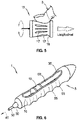
- the actuation button 15 may include a sliding portion 15A to control the longitudinal movement of the medical device 40 and a rotating portion 15B to control rotational movement associated with the medical device 40.
- the sliding portion 15A and rotating portion 15B may be manipulated by different fingers of the user's hand.
- the sliding portion 15A may be manipulated using the thumb finger, while the index finger of the user manipulates the rotating portion 15B.
- one or more of the sliding portion 15A and the rotating portion 15B of the actuation button 15 may include one or more slits 16 in order to provide for added sliding and/or scrolling control.
- the actuation button 15 may in communication or contact with a sliding component 45 configured to secure the medical device 40.
- this sliding component 45 may be, without limitation, a collet 46 that uses a fastener 46A or other type of anchor to secure the medical device 40.
- the longitudinal movement and rotational movement associated with the actuation button 15 may be incorporated such that one finger of the user is capable of controlling both the longitudinal and rotational movement of the medical device by a sliding motion or a scrolling motion, respectively.
- the actuation button 15 may be a thumb wheel capable of being manipulated solely by the thumb finger of the user (e.g., physician) in order to move the medical device 40 both longitudinally and rotationally through a sheath 50.
- the actuation button 15 as shown in FIG. 5 may
- the fins 17 may be disposed around the circumference of the wheel.
- the elongate handle body 10 may include one or more gripping knurls 55, alternatively, a plurality of gripping knurls 55 for providing an user with a firm gripping surface.
- the elongate handle body 10 may represent a singular unified component or include a plurality of components, such as an upper body portion and a lower body portion, that are attached together by gluing, welding, melt bonding, or the like.
- the dimensions of the elongate handle body 10 may be customized in order to fit a specific predetermined hand size or be optimized such that various hand sizes are capable of obtaining a firm grip when using the multipurpose handle 1. Additional ergonomic features may be included in the elongate handle body as well without exceeding the scope of the present disclosure.
- the multipurpose handle 5 including the elongate handle body 10, as well as the various parts contained therein may be formed from polymeric or plastic materials, ceramic materials, metals or metal alloys, and/or combinations thereof.
- the materials for use in the multipurpose handle 5 are selected so that they exhibit desirable or required performance characteristics, such as biocompatibility, flexibility, and strength to name a few.
- the polymeric or plastic materials may include one or more thermoplastic materials or thermoset materials, individually or in combination.
- suitable polymeric or plastic materials may include but not limited to polyamides (e.g., nylons), polyimides, polyethylenes, polyurethanes, polyethers, polyesters, acrylonitrile butadiene styrene (ABS), and mixtures or copolymers thereof.
- the elongate handle body 10 is formed from ABS.
- Any metal parts used within the multipurpose handle 5 may be formed from, without limitation, stainless steel, brass, Nitinol, or a combination thereof.
- the metal parts are formed from brass.
- the elongate handle body 10 may also include a cutout 35 in the form of a longitudinal slot that defines a channel 65 configured to accommodate the sliding action of the actuation button 15.
- This cutout or longitudinal slot 35 is capable of limiting the extent of longitudinal movement within the multipurpose handle 5.
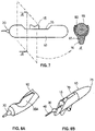
- the actuation button 15 or thumb wheel that fits within the cavity 60 of the cutout 35 may include a tactile bump 65, which can be seen in the cross-section of the actuation button 15 shown in the plane (A) view of FIG. 7 .
- This tactile bump 65 may assist the user in determining the orientation of the attached medical device 40.
- this longitudinal slot may be in the shape of a droplet 35A as shown in FIG. 8A .
- the droplet shaped cutout 35A may vary in size provided the actuation button 15 is secured and cannot slip out of the cavity 60 formed by the cutout 35A ( FIG. 8B ).
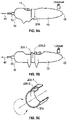
- the locking mechanism 20 may include a locking ring 20A configured to be either be in an unlocked position or a locked position.
- the actuation button 15 may be moved ( FIG. 9A ).
- the locking ring 20A is in the locked position, the actuation button 15 is prevented from moving ( FIG. 9B ).
- the locking ring 20A may include at least one slit 67 that allows one portion of the locking ring 20A-1 to abut against the actuation button 15 when the locking ring 20A is rotated into the locked position ( FIG. 9C ).
- Another portion of the locking ring 20A-2 is located such that it grips or holds a portion of the elongated handle body 10 ( FIG. 9B ).
- Such a locking mechanism 20 may resist inadvertent or accidental movement or retraction of the actuation button 15 or other components in the multipurpose handle 5 during packaging, sterilization, shipping, storage, handling, and preparation for use.
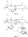
- the elongated handle body 10 may comprise a fin 11 aligned with the longitudinal axis (I) of the elongated handle body 10.
- This fin 11 further comprise a hole 13 located in a position that is easily accessible by the index finger of the user during the operation of the medical device delivery system 1 (see FIG. 10 ).
- the difference (A) between the longitudinal axis (I) of the elongated handle body 10 and the longitudinal axis (II) of the locking member 20 causes the locking member 30 to rotate into the elongated handle body 10 of the multipurpose handle 5 (see FIG. 11 ).
- the locking member 20 may include one or more fins 21 to assist in gripping the mechanism in order to scroll or rotate the member between locked and unlocked positions.
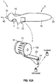
- a sliding locking button 23 is utilized. This locking button 23 slides against a portion of the actuation button 15 in order to prevent movement thereof when in the locked position. Alternatively, the locking button 23 abuts against a side and/or a face 15A of the actuation button 15 or thumb wheel. Alternatively, the locking member 20 or button 23 makes contact with the distal face 15A of the actuation button 15 or thumb wheel. The locking button 23 may slide in an opposite direction in order to unlock and allow the actuation button 15 to move. In this embodiment, the index finger 4 of the user may, together with the thumb finger provide greater control of the actuation button 15.
- the locking button 23 is shown to abut against a face 15A of the actuation button 15.
- the fin 11 in contact with the user's middle or index finger 4 is capable of movement (m) causing the locking button 23 to engage the face 15A of the actuation button 15 in order to establish a locked position.
- the locking button 23 may be held in place through the use of one or more fasteners 24 formed as part of the locking button 23.
- the actuation button 15 may slide over a projection 10B arising from a wall of the elongate handle body 10 to create a locked position. In this locked position, the actuation button 15 is held in place by a spring 70. The actuation button 15 may be released, thereby, creating an unlocked position through the use of the locking button 23.
- the locking button 23 in this case is a push button that overcomes the spring 70 retention and moves the actuation button 15 past the projection 10B in the wall of the elongate body handle 10.
- FIG. 12D Another form of the locking member 20 is shown in FIG. 12D in which the locking button 23 is a spring-loaded lever capable of being pivoted near its fulcrum point 75.
- a spring 71 is positioned such that the locking button 23 is held in a locked position by the spring 71 forcing the lever to contact a face 15A of the actuation button 15. The user is able to release the actuation button 15 by pushing on the locking button 23, thereby overcoming the spring 71 retention and creating an unlocked position.
- the multipurpose handle 1 may include the capability of providing variable locking positions during the operation of the delivery system.
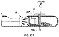
- Variable locking positions may be created, without limitation, through the use of a plurality of splines, ridges, or teeth 80A located in the surface of the actuation button 15 that are appropriately mated or meshed with a plurality of grooves 80B formed in the locking member 20 or vice versa.
- the alignment or meshing of the splines 80A and the grooves 80B creates a locked position that prevents movement of the actuation button 15.
- the different number of splines 80A and grooves 80B that may be meshed or mated together establish variability in the position of the actuation button 15.
- the locking member 20 may include a locking button 23 in which pushing upon the locking button 23 causes the splines 80A and grooves 80B to separate, thereby, creating an unlocked position allowing the actuation button 15 to move.
- the locking member 20 may be integrated with the fin 11 formed as part of the elongate handle body 10.
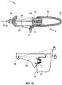
- the locking member 20 includes a pivot point 90 that allows the index finger of the user to apply pressure and push the locking member 20 into contact with the surface of a face 15A of the actuation button 15.
- the locking member 20 acts similar to a lever that is typically in an unlocked position and upon the application of external force or pressure by the user is forced into a locked position.
- the locking button 23 comprises at least one protrusion 93 located on each side of the locking button 23 in order to hold the button 23 in place and prevent the button 23 from being removed (i.e., falling) through the opening present in the elongated handle body 10.
- These protrusions 93 may also act as the pivot point 90A with respect to axis (III) in order for the locking button to establish a locked position and unlocked position.
- the locking button 23 may also be ergonomically curved 95 so that it more appropriately fits the index finger of the user.
- a locking button 23 is forced to abut against a face 15A of the actuation button, thereby, creating a locked position.
- the locking button 23 may be spring-loaded in that a spring forces the multipurpose handle to be in an unlocked or locked state in the absence of pressure applied by the user to the locking button 23.
- the spring 72 as shown in FIG. 15 may provide a sensible and/or audible click associated with locking/unlocking the button 23. In the absence of pressure, the button 23 remains in the state in which it was left with subsequent locking or unlocking having to be done manually. In other words, an external force applied to the locking member that overcomes the force of the spring is able to cause the locking member to move from the unlocked position to the locked position or from the locked position to the unlocked position.
- a medical device delivery system that incorporates the multipurpose handle described above and as further defined herein.
- the medical device delivery system comprises an outer sheath, a medical device, and a multipurpose handle.
- the medical device is located at least partially within, alternatively, entirely within the outer sheath in an initial configuration ready for deployment.
- the outer sheath may be a catheter capable of holding and protecting the medical device while it is pushed endoluminally through a patient's vasculature to a remote treatment or targeted site.
- the outer sheath or catheter is advantageously as small in diameter as possible for a given application, in order to improve endovascular movement and hold the medical device properly in position until its deployment.
- the outer sheath may accommodate the use of a guide wire for tracking the delivery of the medical device to the desired or targeted position.
- the type of medical device is not restricted and may take the form of any known devices, including but not limited to, stents, embolic coils, and vena cava filters.
- the use of a medical device delivery system that incorporates a multipurpose handle as described herein to deliver or retrieve a medical device from a desired or targeted site within a vasculature of a patient's body is believed to be within the scope of the present invention.
- the multipurpose handle provides the user with control over longitudinal movement together with scrolling rotation of the attached medical device. The user may utilize his/her thumb and index finger on a single hand to accomplish such longitudinal and rotational movements.
- medical snare devices for example vascular snare devices, that include a multipurpose handle as disclosed herein.
- any one of the multipurpose handles disclosed in conjunction with FIGs 1-15 can be provided on a medical snare device, wherein the button of the multipurpose handle is operable to control a snare loop or other snare capture structure of the snare device.
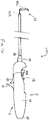
- FIG. 16 shown is one illustrative such medical snare device 100.
- Device 100 includes a multipurpose handle 5 as described in connection with FIGs. 14-15 , although it will be understood that the multipurpose handle can be any of those described herein in conjunction with the illustrative figures or otherwise.
- the sheath 50 (which can be a catheter) is connected to the distal end 30 of the handle 5.
- the medical device 40 is a snare element having a snare loop 40a, although in other forms other snare capture elements such as hooks and/or multiple loops may be included.
- the snare loop 40a or other snare capture element can be connected to a longitudinally extending control rod 40b, which in turn can be connected to control button 15, for example using connection arrangements as described herein.
- Snare loop 40 and control rod 40b can each be made of a single component or multiple components, can be made of any suitable material such as a polymeric and/or metal material, and can be or include solid cross-sectional (e.g.
- snare loop 40a and control rod 40b may be a single integral component.
- snare loop 40a is a braided wire loop.
- the longitudinally extending control rod 40b extends to directly contact and connect with control button, for example being received and secured within control button, for example by a locking mechanism, an adhesive, or both, or other techniques.
- the control rod 40a in this form extends through the lumen of sheath 50 and into the multipurpose handle 5.
- the button 15 When, as illustrated, the button 15 is in its forward (distally positioned) position, the snare loop 40a is deployed from the distal opening of sheath 50.
- the button 15 is in its rearward (proximally positioned) position, the snare loop 40a is positioned within the sheath 50.
- button 15 can be translated distally and proximally to deploy and retract the snare loop 40a, respectively.
- the button 15 can also be rotated to rotate the snare loop 40a.
- the snare loop 40a extends at an angle relative to the longitudinal axis of the control rod 40b, and the button 15 can be rotated to rotate the angled snare loop 40a to different radially positioned capture orientations.
- This can facilitate positioning the loop 40a around a portion of an implanted medical device (which can be a vascular filter, such as a vena cava filter, or any other device described herein for retrieval) to be retrieved, after which the button 15 can be moved proximally to draw the loop 40a partially into the sheath 50 so as to tighten the loop 40a around the implanted medical device.
- the implanted medical device can be drawn into the sheath 50 for removal from the patient.
- the device 100 may be used in conjunction with another sheath or catheter, and the device 100 may be used to draw the implanted medical device into the other sheath or catheter. These and other modes of use for device 100 may be employed.
- Medical snare 100A (for example a vascular snare) can have the same components and functionality as snare 100 described in conjunction with FIG. 16 , except as described hereinbelow.
- Medical snare 100A thus includes a multicomponent handle 5 having an elongate body 10.
- the elongate body 10 of snare 100A defines an internal void 102 surrounding control rod 40b, with void 102 preferably located in a distal region of the handle body 10 and/or distal of the actuation button 15.
- a seal element 104 is received and retained in void 102 and creates a seal between the outer surface of control rod 40b and an internal wall defining void 102.
- the control rod 40b can be frictionally translated proximally and distally through and against seal element 104 and can be frictionally rotated within and against seal element 104, while maintaining the seal between the outer surface of control rod 40b and the internal wall defining void 102.
- the seal element is retained within void 102 during these relative movements between the surface of control rod 40b and the surface of the seal element 104. In this manner, any bodily fluid, for example blood, that passes into the sheath 50 from its distal opening (e.g.
- the seal element can be formed from a resilient material, for example a resilient polymeric material such a silicone or rubber. In some forms, the seal element can define an opening through which control rod 40b extends, and in certain specific forms such a seal element 104 is an O-ring.
- the elongate body 10 of medical snare 100A defines an opening 106 in a wall defining a proximal surface of the void 102, and control rod 40b extends through opening 106.
- elongate body 10 defines an internal wall 108 spaced a distance proximally from opening 106, and internal wall 108 also defines an opening 110 through which control rod 40b extends. Openings 106 and 108, as well as the lumen defined by distal end 30, can help to control the movement of the control rod 40b within handle 5.
- the distal end 30 of the elongate body 10 is formed as a barb having a lumen therethrough, and the snare 100A further includes a cap 112 sealingly fitted over the barb and to the sheath 50.
- snare loop 40a or other snare capture element can be replaced with another medical device structure connected to the control rod 40b and which can be deployed from and retracted into the sheath using movement of the actuation button along the longitudinal axis and can be rotated by rotating the actuation button, as described above.
- Embodiment 1 A multipurpose handle for delivery or retrieval of a medical device, the multipurpose handle comprising:
- Embodiment 2 The multipurpose handle of Embodiment 1 wherein the actuation button is a thumb wheel having a proximal face and a distal face.
- Embodiment 3 The multipurpose handle of Embodiment 2 wherein the thumb wheel includes fins disposed on the circumference of the thumb wheel.
- Embodiment 4 The multipurpose handle of Embodiment 2 or 3 wherein in the locking position, the locking member is in contact with the distal face of the thumb wheel.
- Embodiment 5. The multipurpose handle of any preceding Embodiment, wherein the locking member includes a locking ring.
- Embodiment 6 The multipurpose handle of any of Embodiments 2 to 5, wherein the thumb wheel includes a tactile bump.
- Embodiment 7 The multipurpose handle of any preceding Embodiment, wherein the cutout is droplet shaped.
- Embodiment 8 The multipurpose handle of any preceding Embodiment, wherein the actuation button is placed in the locked position by a sliding component.
- Embodiment 9 The multipurpose handle of any preceding Embodiment, wherein the longitudinal axis of the elongated body and a longitudinal axis of the locking member are located such that the locking mechanism rotates into the elongated body.
- Embodiment 10 The multipurpose handle of any preceding Embodiment, wherein the locking member includes a spring configured to hold the locking member in the locked position or unlocked position.
- Embodiment 11 The multipurpose handle of Embodiment 10, wherein the spring exhibits a force to hold the locking member in the locked position or the unlocked position, such that an external force applied to the locking member that overcomes the force of the spring is able to cause the locking member to move from the unlocked position to the locked position or from the locked position to the unlocked position.
- Embodiment 12 The multipurpose handle of any preceding Embodiment, wherein the actuation button further comprises one or more protrusions configured to prevent the actuation button from being removed from the elongated body.
- Embodiment 13 The multipurpose handle of any preceding Embodiment wherein the locking member includes a locking button configured to slide or be pushed in order to place the actuation button into the locked position.
- Embodiment 14 The multipurpose handle of any preceding Embodiment, wherein the locking member and the actuation button includes a plurality of splines located on one of the locking member or actuation button and a plurality of grooves located on the other one of the actuation button or locking member.
- Embodiment 15 The multipurpose handle of Embodiment 14, wherein the locking position is variable due to the different number of splines that are aligned or meshed with the grooves.
- a medical device delivery system comprising:
- Embodiment 17 The medical device delivery system of Embodiment 16, wherein the medical device is a stent, an embolic coil, or a vena cava filter.
- Embodiment 18 The medical device delivery system of Embodiment 16 or 17, wherein the actuation button is placed in the locked position by a sliding component.
- Embodiment 19 The use of the medical device delivery system of Embodiment 16 for delivering or retrieving a medical device from a targeted site in a vasculature of a patient.
- Embodiment 20 The use of the multipurpose handle of any one of Embodiments 1 to 15 in a medical device delivery system configured to deliver or retrieve a medical device from a targeted site in a vasculature of a patient.
Landscapes
- Health & Medical Sciences (AREA)
- Life Sciences & Earth Sciences (AREA)
- Surgery (AREA)
- Engineering & Computer Science (AREA)
- Biomedical Technology (AREA)
- Veterinary Medicine (AREA)
- Public Health (AREA)
- General Health & Medical Sciences (AREA)
- Heart & Thoracic Surgery (AREA)
- Animal Behavior & Ethology (AREA)
- Molecular Biology (AREA)
- Medical Informatics (AREA)
- Nuclear Medicine, Radiotherapy & Molecular Imaging (AREA)
- Vascular Medicine (AREA)
- Cardiology (AREA)
- Oral & Maxillofacial Surgery (AREA)
- Transplantation (AREA)
- Orthopedic Medicine & Surgery (AREA)
- Reproductive Health (AREA)
- Surgical Instruments (AREA)
Applications Claiming Priority (1)
| Application Number | Priority Date | Filing Date | Title |
|---|---|---|---|
| US202163222404P | 2021-07-15 | 2021-07-15 |
Publications (1)
| Publication Number | Publication Date |
|---|---|
| EP4119072A1 true EP4119072A1 (fr) | 2023-01-18 |
Family
ID=82608349
Family Applications (1)
| Application Number | Title | Priority Date | Filing Date |
|---|---|---|---|
| EP22185267.6A Pending EP4119072A1 (fr) | 2021-07-15 | 2022-07-15 | Poignées multifonctions et anse médicale ou d'autres dispositifs les comprenant |
Country Status (3)
| Country | Link |
|---|---|
| US (1) | US12575853B2 (fr) |
| EP (1) | EP4119072A1 (fr) |
| CN (1) | CN115607238A (fr) |
Families Citing this family (2)
| Publication number | Priority date | Publication date | Assignee | Title |
|---|---|---|---|---|
| CN116650796B (zh) * | 2023-06-21 | 2026-01-20 | 科睿驰(深圳)医疗科技发展有限公司 | 导管手柄及可控弯微导管 |
| FR3166533A1 (fr) * | 2024-09-20 | 2026-03-27 | Id Nest Medical | Dispositif universel de largage d’implants du genre stents ou endoprotheses |
Citations (4)
| Publication number | Priority date | Publication date | Assignee | Title |
|---|---|---|---|---|
| US20030109889A1 (en) * | 2001-12-12 | 2003-06-12 | Steve Mercereau | Articulating stone basket |
| US20130079758A1 (en) * | 2011-09-23 | 2013-03-28 | Cook Medical Technologies Llc | Snare system |
| US20170172389A1 (en) * | 2014-09-05 | 2017-06-22 | Olympus Corporation | Endoscopic treatment instrument, treatment instrument unit, and treatment system |
| US20200222218A1 (en) * | 2019-01-14 | 2020-07-16 | Cook Medical Technologies Llc | Multipurpose handle |
Family Cites Families (6)
| Publication number | Priority date | Publication date | Assignee | Title |
|---|---|---|---|---|
| US6258101B1 (en) * | 2000-03-24 | 2001-07-10 | Lacey Manufacturing Company, Inc. | Instrument for deploying surgical devices |
| US7951073B2 (en) * | 2004-01-21 | 2011-05-31 | Boston Scientific Limited | Endoscopic device having spray mechanism and related methods of use |
| US20090210046A1 (en) * | 2008-02-20 | 2009-08-20 | Abbott Laboratories | Handle assembly for a delivery system |
| US9622765B2 (en) * | 2008-10-23 | 2017-04-18 | Covidien Lp | Vacuum assisted surgical dissection tools |
| AU2015264609B2 (en) * | 2014-05-21 | 2017-12-07 | Boston Scientific Scimed, Inc. | Stent delivery system |
| US11304747B2 (en) * | 2016-11-16 | 2022-04-19 | Boston Scientific Scimed, Inc. | Rotatable snares and related methods |
-
2022
- 2022-07-15 US US17/865,454 patent/US12575853B2/en active Active
- 2022-07-15 EP EP22185267.6A patent/EP4119072A1/fr active Pending
- 2022-07-15 CN CN202210836575.1A patent/CN115607238A/zh active Pending
Patent Citations (4)
| Publication number | Priority date | Publication date | Assignee | Title |
|---|---|---|---|---|
| US20030109889A1 (en) * | 2001-12-12 | 2003-06-12 | Steve Mercereau | Articulating stone basket |
| US20130079758A1 (en) * | 2011-09-23 | 2013-03-28 | Cook Medical Technologies Llc | Snare system |
| US20170172389A1 (en) * | 2014-09-05 | 2017-06-22 | Olympus Corporation | Endoscopic treatment instrument, treatment instrument unit, and treatment system |
| US20200222218A1 (en) * | 2019-01-14 | 2020-07-16 | Cook Medical Technologies Llc | Multipurpose handle |
Also Published As
| Publication number | Publication date |
|---|---|
| US20230021086A1 (en) | 2023-01-19 |
| CN115607238A (zh) | 2023-01-17 |
| US12575853B2 (en) | 2026-03-17 |
Similar Documents
| Publication | Publication Date | Title |
|---|---|---|
| US12396872B2 (en) | Multipurpose handle | |
| US12408918B2 (en) | Anchor magazine | |
| EP1380271B1 (fr) | Mécanisme de deploiement d'une manche à serrage pour un dispositif médical | |
| US8535366B2 (en) | Implantable device delivery system handle and method of use | |
| EP2769684B1 (fr) | Dispositif de suture chirurgicale | |
| JP5108882B2 (ja) | 静脈カテーテル挿入装置 | |
| EP4119072A1 (fr) | Poignées multifonctions et anse médicale ou d'autres dispositifs les comprenant | |
| US20160113644A1 (en) | Biceps Tenodesis Delivery Tools | |
| JP7499897B2 (ja) | セルフロック式、マルチポジション、およびスライドボタン式の直線的に作動可能な格納式ブレードまたはフックを備える軟部組織切断器具 | |
| JP2002330946A (ja) | 血液採集組み立て品 | |
| US6979340B2 (en) | Single use, self-contained twist resistant surgical knife | |
| EP3700476B1 (fr) | Système de cathéter de pose de stent à commande de vitesse lente par l'intermédiaire d'une broche et d'une fente avec une languette de commande de vitesse rapide | |
| US20210322725A1 (en) | A medical device for deploying a cathether that can be operated with a single hand, and a method | |
| JP2017508575A (ja) | ステント留置装置 |
Legal Events
| Date | Code | Title | Description |
|---|---|---|---|
| PUAI | Public reference made under article 153(3) epc to a published international application that has entered the european phase |
Free format text: ORIGINAL CODE: 0009012 |
|
| STAA | Information on the status of an ep patent application or granted ep patent |
Free format text: STATUS: THE APPLICATION HAS BEEN PUBLISHED |
|
| AK | Designated contracting states |
Kind code of ref document: A1 Designated state(s): AL AT BE BG CH CY CZ DE DK EE ES FI FR GB GR HR HU IE IS IT LI LT LU LV MC MK MT NL NO PL PT RO RS SE SI SK SM TR |
|
| STAA | Information on the status of an ep patent application or granted ep patent |
Free format text: STATUS: REQUEST FOR EXAMINATION WAS MADE |
|
| 17P | Request for examination filed |
Effective date: 20230718 |
|
| RBV | Designated contracting states (corrected) |
Designated state(s): AL AT BE BG CH CY CZ DE DK EE ES FI FR GB GR HR HU IE IS IT LI LT LU LV MC MK MT NL NO PL PT RO RS SE SI SK SM TR |
|
| STAA | Information on the status of an ep patent application or granted ep patent |
Free format text: STATUS: EXAMINATION IS IN PROGRESS |
|
| 17Q | First examination report despatched |
Effective date: 20231213 |