EP4119074A1 - Nadelrillenplatte, punktionsträger und biopsievorrichtung - Google Patents
Nadelrillenplatte, punktionsträger und biopsievorrichtung Download PDFInfo
- Publication number
- EP4119074A1 EP4119074A1 EP20923875.7A EP20923875A EP4119074A1 EP 4119074 A1 EP4119074 A1 EP 4119074A1 EP 20923875 A EP20923875 A EP 20923875A EP 4119074 A1 EP4119074 A1 EP 4119074A1
- Authority
- EP
- European Patent Office
- Prior art keywords
- needle groove
- needle
- arm
- main body
- rod
- Prior art date
- Legal status (The legal status is an assumption and is not a legal conclusion. Google has not performed a legal analysis and makes no representation as to the accuracy of the status listed.)
- Granted
Links
Images






Classifications
-
- A—HUMAN NECESSITIES
- A61—MEDICAL OR VETERINARY SCIENCE; HYGIENE
- A61B—DIAGNOSIS; SURGERY; IDENTIFICATION
- A61B17/00—Surgical instruments, devices or methods
- A61B17/34—Trocars; Puncturing needles
- A61B17/3403—Needle locating or guiding means
-
- A—HUMAN NECESSITIES
- A61—MEDICAL OR VETERINARY SCIENCE; HYGIENE
- A61B—DIAGNOSIS; SURGERY; IDENTIFICATION
- A61B10/00—Instruments for taking body samples for diagnostic purposes; Other methods or instruments for diagnosis, e.g. for vaccination diagnosis, sex determination or ovulation-period determination; Throat striking implements
- A61B10/02—Instruments for taking cell samples or for biopsy
- A61B10/0233—Pointed or sharp biopsy instruments
- A61B10/0241—Pointed or sharp biopsy instruments for prostate
-
- A—HUMAN NECESSITIES
- A61—MEDICAL OR VETERINARY SCIENCE; HYGIENE
- A61B—DIAGNOSIS; SURGERY; IDENTIFICATION
- A61B17/00—Surgical instruments, devices or methods
- A61B17/00234—Surgical instruments, devices or methods for minimally invasive surgery
- A61B2017/00238—Type of minimally invasive operation
- A61B2017/00274—Prostate operation, e.g. prostatectomy, turp, bhp treatment
-
- A—HUMAN NECESSITIES
- A61—MEDICAL OR VETERINARY SCIENCE; HYGIENE
- A61B—DIAGNOSIS; SURGERY; IDENTIFICATION
- A61B17/00—Surgical instruments, devices or methods
- A61B17/34—Trocars; Puncturing needles
- A61B17/3403—Needle locating or guiding means
- A61B2017/3405—Needle locating or guiding means using mechanical guide means
- A61B2017/3411—Needle locating or guiding means using mechanical guide means with a plurality of holes, e.g. holes in matrix arrangement
-
- A—HUMAN NECESSITIES
- A61—MEDICAL OR VETERINARY SCIENCE; HYGIENE
- A61B—DIAGNOSIS; SURGERY; IDENTIFICATION
- A61B17/00—Surgical instruments, devices or methods
- A61B17/34—Trocars; Puncturing needles
- A61B17/3403—Needle locating or guiding means
- A61B2017/3413—Needle locating or guiding means guided by ultrasound
-
- A—HUMAN NECESSITIES
- A61—MEDICAL OR VETERINARY SCIENCE; HYGIENE
- A61B—DIAGNOSIS; SURGERY; IDENTIFICATION
- A61B8/00—Diagnosis using ultrasonic, sonic or infrasonic waves
- A61B8/12—Diagnosis using ultrasonic, sonic or infrasonic waves in body cavities or body tracts, e.g. by using catheters
Definitions
- the present invention relates to the technical field of medical supplies, in particular to a needle groove plate, a puncture support and a biopsy device.
- Prostate disease is a common disease especially among older men.
- prostate biopsy is used to detect and troubleshoot prostate diseases.
- ultrasound biopsy a small amount of sample tissues needs to be taken out from different parts of the prostate for the purpose of diagnosis.
- Biopsy is less invasive and more accurate, and thus has been widely used in clinic applications.
- Common sampling ways of biopsy are by way of rectum and by way of perineum.
- the existing needle groove plate is a square grid screen plate, on which hundreds of needle penetration holes are arranged in an array.
- the needle groove plate is fixedly mounted on the puncture support by a dedicated stepper. When in use, the stepper is adjusted to make the puncture support of the grid screen plate abut against a patient's perineum.
- the ultrasonic probe connected to the puncture support goes from the patient's anus into the prostate position, and selects an appropriate hole position of the grid screen plate to insert the needle. After the puncture needle is inserted into the patient's perineum, it reaches the position in the prostate that needs to be punctured.
- the present invention provides a needle groove plate, a puncture support and a biopsy device, which have advantages of a simple structure, low costs, flexible and convenient operations, and capability of achieving separation of the penetration needle in surgery.
- a needle groove plate which includes a needle groove arm and a clamping component, wherein: the needle groove arm is provided with a plurality of parallel needle penetration holes arranged along the vertical direction of the needle groove arm and penetrating the needle groove arm along the horizontal direction of the needle groove arm; and the clamping component is located at the bottom of the needle groove arm for connecting a puncture support.
- a plurality of beams is provided in parallel along the vertical direction of the needle groove arm, and the needle penetration holes are voids between the plurality of beams.
- the width of an entrance into the needle penetration holes from a radial direction of the needle penetration holes is smaller than an inner diameter of the needle penetration holes.
- the needle penetration holes have an intact inner wall.
- the needle groove arm includes a main body portion and a cooperating portion, wherein: an abutting surface of the cooperating portion is provided with a plurality of parallel grooves that are arranged along the vertical direction of the needle groove arm and penetrate the needle groove arm along the horizontal direction of the needle groove arm; and an abutting surface of the main body portion fits the abutting surface of the cooperating portion to form a hole having an intact inner wall.
- the main body portion and the cooperating portion are connected by a connecting component;
- the connecting component includes a hole located in the top of the main body portion and a buckle located in the top of the cooperating portion, the buckle includes a first board perpendicular to the abutting surface of the cooperating portion, a free end of the first board is connected with a second board arranged in parallel with the first board, the first board and the second board form a U-shaped structure, a free end of the second board extends and protrudes out of a surface of the cooperating portion, the said surface is a plane that located away from the abutting surface, an upper surface of the second board is provided with a protruding structure that has a fourth inclined surface and a fourth straight end surface; and/or, the bottom of the main body portion is provided with an abutting platform that abuts against the bottom of the cooperating portion, the abutting platform is provided with a groove, and the bottom of the cooperating portion is provided with a protrusion to be inserted
- the clamping component includes a protruding structure and two insertion arms, wherein: the two insertion arms are provided along the horizontal direction of the needle groove arm, specifically at an edge of the bottom of the needle groove arm; and the protruding structure is provided in the bottom of the needle groove arm and is located between the two insertion arms, and the protruding structure includes a third inclined surface and a third straight end surface.
- one end of the insertion arms has an insertion end, and the other end is a position limit end, the position limed end is provided with a protruding stop block along a surface of the insertion arms.
- a puncture support which includes a main body, a rod, and the needle groove plate, wherein: the main body is connectable to an ultrasonic probe and has a channel whose length is smaller than the length of the rod; the rod can, from a first end thereof, go into the channel, and slide back and forth in the channel along a first direction that is parallel to an extending direction of the rod; and the needle groove plate is fixed to a second end of the rod.
- the main body includes a hold hoop and two L-shaped walls with a spacing; the hold hoop is used to connect the ultrasonic probe; and the L-shaped walls include vertical walls and horizontal walls, wherein the vertical walls extend from an outer surface of the hold hoop towards the direction away from the hold hoop, two horizontal walls respectively extend from free sides of two vertical walls towards each other, and the free sides are parallel to the first direction, so that the two L-shaped walls and an outer wall of the hold hoop form the channel.
- the hold hoop includes a hold hoop main body having an arch-shaped cross section and an arch-shaped wrench connected with the hold hoop main body, and the L-shaped walls are located on the hold hoop main body; and one end of the wrench is connected right next to one edge of the hold hoop main body ; and a first stepped edge is located next to the other edge of the hold hoop main body , the other end of the wrench is provided with a second stepped edge for clamping the first stepped edge so that the hold hoop main body and the wrench form a closed loop.
- an upper surface of a main arm of the rod includes an upper boss that protrudes upwards so as to be located between the two horizontal walls and extend along the first direction; and a plurality of pits are arranged in one line along surfaces of two side walls of the upper boss along the first direction; the two horizontal walls have notches at the same positions in the first direction; the puncture support further has a push button and two first elastic arms, wherein: a fixed end of the first elastic arms is fixed to an inner wall at an entrance of the notches, and the first elastic arms are parallel to the first direction, so that the first elastic arms and the notches form a hole, and free ends of the two first elastic arms are provided with convex points, and two convex points protrude towards each other; the push button includes a push button platform and two fixed arms, the fixed arms are located on a lower surface of the push button platform and are perpendicular to the push button platform, the fixed arms are inserted into the hole and can slide in the hole along the first direction, roots of the fixed arms have a first
- the first section of fixed arms is provided with a second section of fixed arms extending towards the direction away from the push button platform, a U-shaped groove parallel to the first direction is formed between the second section of fixed arms and the first section of fixed arms, and part of edges of both sides of the main arm are located in the U-shaped groove; and an upper surface of the push button platform is provided with a hand position slot and/or an identification portion.
- a lower portion of the rod has a groove extending along the first direction, and an accommodating space is formed between the groove and an outer wall of the hold hoop; a wall of the hold hoop is provided with a single hole in which a second elastic arm is provided, the single hole is located on the wall of the hold hoop in the channel and close to one end of the channel away from the needle groove plate; and the second elastic arm is parallel to the first direction, a fixed end of the second elastic arm is fixed to an end surface of the wall of the hold hoop, and a free end of the second elastic arm is provided with a protruding structure that includes a first straight end surface whose height is greater than a wall thickness of the hold hoop, so that the protruding structure protrudes towards the interior of the channel and goes into the accommodating space; and the first end of the rod has an end wall perpendicular to the first direction, and an inner side of the end wall can be blocked by the first straight end surface during the sliding process of the rod so as to stop sliding.
- a front end of the main arm is provided with two auxiliary arms in parallel extending along the first direction, a defined spacing is provided between the two auxiliary arms, and inner sides of the two auxiliary arms are each provided with protruding blocking walls protruding towards each other;
- a lower surface of the main arm is provided with a lower boss provided along a length direction thereof, a surface of the lower boss fits an outer wall of the hold hoop, the lower boss extends to below a lower portion of the auxiliary arms, the bottom of one end of the two auxiliary arms away from the main arm is connected to the beams, a third elastic arm arranged along a sliding direction of the rod is provided between the two auxiliary arms, both ends of the third elastic arm are respectively connected with an end portion of the main arm and the beams, and an upper surface of the third elastic arm is provided with a protruding structure that includes a second inclined surface and a second straight end surface; insertion arms are inserted between the two auxiliary arms, an upper surface of the insertion arms fits a lower surface
- both ends of the beams respectively protrude towards directions of both sides of the first direction so as to abut against an end surface of a second end of the hold hoop close to the rod to form a limit position.
- a biopsy device which includes an ultrasonic probe and the puncture support, wherein the hold hoop of the puncture support is sleeved on an outer wall of the ultrasonic probe.
- the outer wall of the ultrasonic probe is provided with a position limit protrusion
- the hold hoop is provided with a slot for clamping the position limit protrusion
- the existing square puncture support is replaced with the needle groove plate, and the needle groove plate is in a clamping connection with the puncture support without a need for a stepper structure, which not only optimizes the structure of the puncture support and reduces its volume, but also reduces manufacturing costs.
- the needle penetration hole can adopt a groove shaped non-closed hole, so that the penetration needle can be separated from the puncture support and the ultrasonic probe during surgery, thereby facilitating flexible operations by the doctor.
- the structure of a puncture support is effectively optimized, which can not only reduce its sizes and costs, but also facilitate flexible operations by a doctor and reduce a patient's discomfort in use. It will be described below in detail.
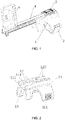
- Fig. 1 is a structural schematic diagram of a puncture support according to an embodiment of the present invention.
- the puncture support according to the present invention includes a main body 1, a wrench 2, a push button 3, a rod 4 and a needle groove plate 5, wherein the main body 1 and the wrench 2 are used to connect an ultrasonic probe, a first end of the rod 4 is inserted into the main body 1, a second end of the rod 4 is connected with the needle groove plate 5, the rod 4 can slide back and forth along an extending direction thereof (the left-right direction according to the perspective in the figure, and the sliding direction will be called "a first direction” below), and the push button 3 can lock the rod 4 during the sliding process.
- the structure of the puncture support will be further described below.
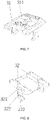
- Fig. 2 is a structural schematic diagram of the main body.
- the main body 1 includes a hold hoop 11 and two L-shaped walls 12 with a spacing in between; the hold hoop 11 is used to connect the ultrasonic probe; and the L-shaped walls 12 include vertical walls 123 and horizontal walls 124, wherein the vertical walls 123 extend from an outer surface of the hold hoop 11 towards the direction (an upward direction according to the perspective in the figure) away from the hold hoop 11, two horizontal walls 124 respectively extend from free sides of two vertical walls 123 towards each other, and the free sides are parallel to the first direction, so that the two L-shaped walls 12 and an outer wall of the hold hoop 11 form the channel 13.
- Fig. 3 is a structural schematic diagram of the main body from another perspective.
- the L-shaped walls 12 are provided above a hold hoop main body of the hold hoop 11, and one side of the hold hoop main body is provided with a first stepped edge 111 (shown in Fig. 2 ), and the other side thereof is provided with a rotary shaft 112 (shown in Fig. 3 ).
- the hold hoop 11 further includes a wrench 2 used to connect the hold hoop main body;
- Fig. 4 is a structural schematic diagram of the wrench;
- Fig. 5 is a structural schematic diagram of the wrench from another perspective; as shown in Figs. 4 and 5 , the main body of the wrench is an arch-shaped portion 22 that has a certain elastic deformation capability.
- One end of the arch-shaped portion 22 is provided with a rotary sleeve 21, and the other end of the arch-shaped portion 22 is provided with a second stepped edge 23 for clamping the first stepped edge 111, wherein, a hand position 24 is further provided at the second stepped edge 23.
- the rotary sleeve 21 is a cylinder provided with an opening whose width is smaller than an inner diameter of the cylinder, and the rotary sleeve 21 has a certain elastic deformation capability to make the width of the opening varies, and further make the rotary sleeve 21 capable of clamping a connecting shaft 112, so that the wrench 2 is rotatable about the rotary shaft 112 within a certain range.
- the first stepped edge 111 can occlude with the second stepped edge 23 provided on the wrench 2, the inclination directions of the steps of the first stepped edge and the second stepped edge make the two only movable towards each other in the direction of reducing the inner diameter of the hold hoop in the contact state.
- the other end of the wrench 2 needs to be pulled, so that the first stepped edge 111 is separated from the second stepped edge 23.
- the puncture support is sleeved on the ultrasonic probe, it is only required to hold the hold hoop at the thumb-index web of an operator's hand and then apply a force to tighten up the hold hoop.
- multi-step stepped edges make the hold hoop suitable for various diameters of the puncture support, thereby improving applicability of the puncture support.
- the hold hoop main body and the wrench 2 can also be set as an integral structure. That is, the hold hoop main body and the wrench 2 enclose a closed loop with a constant inner diameter, friction between an inner surface of the hold hoop and an outer surface of the ultrasonic probe is used to sleeve the closed-loop structure on the ultrasonic probe when the puncture support is connected with the ultrasonic probe.
- Fig. 6 is a structural schematic diagram of adding a rubber pad to the wrench.
- a rubber pad 6 is provided on an inner wall of the arch-shaped portion 22 along its radian direction, the soft rubber pad 6 is made of soft materials such as rubber, TPE or TPU, and is fixedly connected, e.g., bonded, to the arch-shaped portion 22.
- the puncture support can be assembled better, and friction between the puncture support and the ultrasonic probe can be increased, thereby facilitating a stabler assembling.
- the rubber pad 6 is of an elastomer material, the ultrasonic probe can be protected from being scratched and damaged when the puncture support is mounted and dismounted.
- Fig. 7 is a structural schematic diagram of the push button
- Fig. 8 is a structural schematic diagram of the push button from another perspective.
- the push button 3 includes a push button platform 31 and two fixed arms 32 located on the lower surface of the push button platform 31 and perpendicular to the push button platform 31.
- the upper surface of the push button platform 31 is provided with a hand position slot 311 and/or an identification portion.
- the hand position slot 311 can increase friction between figures and the hand position slot 311 during in use, and the identification portion is character and/or pattern information to facilitate the user to know about functions and operation method of the push button 3.
- Fig. 9 is a structural schematic diagram of the rod.
- the rod 4 includes a main arm 41, an upper boss 42 provided above the main arm 41, and a lower boss 43 provide below the main arm 41.
- the upper boss 42 and the lower boss 43 extend along the length direction of the main arm 41, and the three are an integral structure. That is, the shape of the cross section of the rod 4 is similar to the "+" character.
- the rod 4 can, from its first end (a proximal end according to the perspective of Fig. 9 ) go into a channel 13, the length of the channel 13 is less than the length of the rod 4, so that after the rod 4 goes into the channel 13, part of the rod 4 is located outside the channel 13 and a needle groove plate can be mounted.
- the rod 4 can slide back and forth in the channel 13 along the first direction. In this state, the upper boss 42 is located between two horizontal walls 124, and the surface of the lower boss 43 fits the outer wall of the hold hoop 11 .
- Fig.10 is a structural schematic diagram of the rod being connected with the needle groove plate.
- the needle groove plate 5 is fixed to the second end of the rod 4 (i.e., a distal end in Fig. 9 ), and the needle groove plate 5 is provided with at least one needle penetration hole 513 parallel to the first direction.
- the structure of the needle groove plate will be described below.
- the push button 3 can be used to lock the rod 4 so as to limit expansion position of the rod 4 on the main body 1 and achieve the purpose of adjusting the position of the needle groove plate 5.
- a plurality of pits 421 are arranged in one line along surfaces of two side walls of the upper boss 42 along the first direction.
- Fig. 11 is a structural schematic diagram of the top of the main body.
- Fig. 12 is a sectional view of the first elastic arm along the first direction. As shown in Figs.
- the two horizontal walls 124 have notches 122 in the same positions in the first direction
- the fixed end of the first elastic arm 121 is fixed to the inner wall at the entrance of the notches122
- the first elastic arm 121 is parallel to the first direction, so that the first elastic arm 121 and the notches 122 form the hole 120.
- Free ends of two first elastic arms 121 are provided with convex points 1211, and two convex points 1211 protrude towards each other.
- the fixed arms 32 When the push button 3 is connected with the main body 1, the fixed arms 32 are inserted into the hole 120 and can slide in the hole 120 along the first direction, roots of the fixed arms 32 have a first section 321 of fixed arms protruding towards the entrance of the notches 122, the first section 321 of fixed arms abuts against the first elastic arms 121 when the first section 321 of fixed arms is located at the free ends of the first elastic arms 121, then the first section of fixed arms 321 can limit the opening of the free ends of the first elastic arms 121 so that the convex points 1211 cannot be separated from the pits 421 and the first elastic arms 121 lock tightly the rod 4 to achieve the purpose of limiting free sliding of the rod 4 along the first direction.
- the convex points 1211 can break away from the pits 421 under the action of external force, and if continuing to apply a pulling force to the rod 4, the convex points 1211 repeat acts of getting into the pits 421 and breaking away from the pits 421 until the rod 4 moves to a target position.
- the convex points 1211 get into the pits 421, the first section 321 of fixed arms is moved to the free end of the first elastic arms 121, and the first section 321 of fixed arms locks tightly the rod 4 again to complete adjustments of the position of the rod 4.
- the first section 321 of fixed arms is provided with a second section 323 of fixed arms extending towards a direction away from the push button platform 31, a U-shaped groove 322 parallel to the first direction is formed between the second section 323 of fixed arms and the first section 321 of fixed arm, and in the state shown in Fig. 1 , part of edges of both sides of the main arm 41 are located in the U-shaped groove 322.
- Fig. 13 is a structural schematic diagram of the lower surface of the rod (according to the perspective of Fig.1 ). As shown in Fig. 13 , there is a groove 47 extending along the first direction below the rod 4 (in Fig. 13 , the rod 4 is in a flip state that the lower surface is placed upwards), the groove 47 can form an accommodation space with the outer wall of the hold hoop 11. As shown in Fig. 13 , the rod 4 is in a flip state that the lower surface is placed upwards), the groove 47 can form an accommodation space with the outer wall of the hold hoop 11. As shown in Fig.
- the wall of the hold hoop 11 is provided with a single hole 134, and a second elastic arm 131 is provided in the single hole 134.
- the second elastic arm 131 has a certain elastic deformation capability, and the single hole 134 is located on the wall of the hold hoop 11 in the channel 13 and close to one end of the channel 13 away from the needle groove plate 5 (see Fig. 1 ).
- the second elastic arm 131 is parallel to the first direction, the fixed end of the second elastic arm 131 is fixed to the end surface of the wall of the hold hoop 11 and the free end of the second elastic arm 131 is provided with a protruding structure 130, and the protruding structure 130 includes a first straight end surface 133 and a first inclined surface 132 whose height is greater than a wall thickness of the hold hoop 11, so that the protruding structure 130 protrudes towards the interior of the channel 13 and goes into the accommodating space formed between the groove 47 and the outer wall of the hold hoop 11.
- the first end of the rod 4 has an end wall 46 perpendicular to the first direction.
- the rod 4 when the rod 4 slides in the channel 13 towards the outer side of the end wall 46 in the upper right of Fig.11 during an inserting sliding process, the rod 4 passes the first inclined surface 132, then an inner side 461 is blocked by the first straight end surface 133 from the retracting sliding process of the rod 4 in the channel 13 in the lower left of Fig. 11 thus lock the rod 4 in place, so the rod 4 cannot exit from the channel 13.
- the protruding structure 130 is enclosed in the accommodating space so that the rod 4 cannot be easily disassembled from the channel 13, which facilitates realizing disposable use of the puncture support and improving sanitation and safety.
- Fig. 14 is a structural schematic diagram of another perspective of the rod.
- Fig.15 is a sectional view of the front end of the rod.
- the front end of the main arm 41 is provided with two auxiliary arms 411 that are parallel at edges of both sides of the main arm 41 and extend along the first direction, the two auxiliary arms 411 extend from edges of both sides of the main arm 41 and thus there is a space formed therebetween.
- the inner sides of the two auxiliary arms 411 are each provided with protruding blocking walls 4111, and two blocking walls 4111 protrude towards each other.
- the lower boss 43 is extended under the auxiliary arms 411, and the bottom of one end of the two auxiliary arms 411 that is away from the main arm 41 is connected to the beam 45.
- a third elastic arm 44 provided along the sliding direction of the rod 4 is provided between the two auxiliary arms 411, both ends of the third elastic arm 44 are respectively connected with the end portion of the main arm 41 and the beam 45, the upper surface of the third elastic arm 44 is provided with a protruding structure 440 that includes a second inclined surface 441 and a second straight end surface 442 .
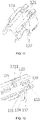
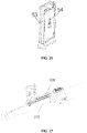
- Fig. 16 is a structural schematic diagram of a needle groove plate of a semi-closed needle penetration hole
- Fig. 17 is a structural schematic diagram of another perspective of Fig. 16
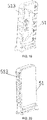
- Fig. 18 is a structural schematic diagram of the bottom of the needle groove plate.
- the needle groove plate 5 includes a needle groove arm 51 and two insertion arms 52, wherein the needle groove arm 51 is provided with a depth identifier 511 and a specification identifier 512, and the two insertion arms 52 are provided at the edge of the bottom of the needle groove arm 51 along the horizontal direction of the needle groove arm 51.
- the bottom surface of the needle groove arm 51 is provided with a protruding structure 520 located between the two insertion arms 52.
- the protruding structure 520 includes a third inclined surface 521 and a third straight end surface 522.
- the insertion arms 52 are inserted between the two auxiliary arms 411, and the upper surfaces of the insertion arms 52 fit the lower surfaces of the blocking walls 4111, the positions of the second inclined surface 441 and the second straight end surface 442, and the third inclined surface 521 and the third straight end surface 522 are so set that the second straight end surface 442 abuts against the third straight end surface 522, and thereby the insertion arms 52 cannot move towards the left (see Fig. 10 ) and accordingly cannot exit from between the two auxiliary arms 411.
- the insertion arms 52 are blocked by the upper boss 42 of the main arm 4 when moving towards the right, so that the needle groove plate 5 is fixed to the main arm 4.
- the second straight end surface 442 and the third straight end surface 522 that abut against each other cannot be reached from the outside, and thus the abutting state cannot be removed without causing damages, thereby realizing disposable use of medical devices and improving sanitation and safety.
- both ends of the beam 45 respectively protrude towards the left and the right so as to abut against the end surface of the second end of the hold hoop 11 close to the rod 4 to form a limiting position.
- the limiting position structure cooperates with the limiting position structure of the end wall 46 of the other end of the rod 4 so that there are both limiting positions at both ends of the rod 4 and the rod 4 cannot be separated from the main body 1. This also helps to realize disposable use of the medical devices.
- the needle penetration hole 513 is a fully closed hole or a semi-closed hole, wherein, a plurality of beams are provided in parallel on the side wall of the needle groove arm 51 along the vertical direction of the needle groove arm 51, and spacing between the plurality of beams forms a semi-closed hole; or, the needle penetration hole 513 is a hole having a full inner wall and penetrating the needle groove plate 5, and is a fully closed hole. As shown in Figs. 16 and 17 , the needle penetration hole 513 in the needle groove plate 5 is a semi-closed hole.
- Fig. 19 is a structural schematic diagram of a needle groove plate of a fully closed needle penetration hole.
- FIG. 20 is a structural schematic diagram of another perspective of Fig. 19 .
- the needle penetration hole 513 in the needle groove plate 5 in Figs. 19 and 20 is a fully closed hole.
- the position of the needle penetration hole 513 is in one-to-one correspondence with the position of the depth identifier 511, and conforms to the needle insertion route set by software in an ultrasound machine.
- the size of the needle penetration hole 513 is in one-to-one correspondence with the specification identifier 512.
- the model of the needle penetration hole 513 can be selected according to the actual needs, wherein, when the semi-closed hole structure is used, a puncture needle or a biopsy needle can be rapidly moved in parallel out of the opening of the needle penetration hole 513 when the doctor requires the puncture needle to be separated from a puncture needle support, so that the ultrasonic probe and the puncture support can be rapidly removed and the puncture needle can be left alone in the human body for operations such as drug delivery or treatment.
- Fig. 21 is a structural schematic diagram of the main body
- Fig. 22 is a structural schematic diagram of the cooperating portion
- Fig. 23 is a structural schematic diagram of the buckle of the top of the cooperating portion
- Fig. 24 is a structural schematic diagram of the protrusion in the bottom of the cooperating portion.
- the needle groove plate 5 can further adopt a split structure.
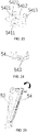
- the needle groove arm 51 includes a main body portion 53 and a cooperating portion 54, a groove 5131 is provided on an abutting surface of the cooperating portion 54, and an abutting surface of the cooperating portion 53 abuts against the cooperating portion 54 to form a closed hole.
- the main body portion 53 and the cooperating portion 54 are connected by a connecting component.
- the connecting component includes a hole 531 located on the top of the main body portion 53 and a buckle 541 located on the top of the cooperating portion 54, the buckle 541 includes a first board 5411 perpendicular to the abutting surface of the cooperating portion 54, a free end of the first board 5411 is connected with a second board 5412 provided parallel to the first board 5411, the first board 5411 and the second board 5412 form a U-shaped structure, a free end of the second board 5412 extends and protrudes out of the surface of the cooperating portion 54, the extends and protrudes out of surface is a plane away from the abutting surface of the cooperating portion 54, and the upper surface of the second board 5412 is provided with a protruding structure 542 that has a fourth inclined surface 5421 and a fourth straight end surface 5422.
- the bottom of the main body portion 53 is provided with an abutting platform 532 that abuts against the bottom of the cooperating portion 54, the abutting platform is provided with a groove 533, and the bottom of the cooperating portion 54 is provided with a protrusion 543 to be inserted into the groove 533.
- Fig. 25 is a structural schematic diagram when the main body portion and the cooperating portion are assembled
- Fig. 26 is a structural schematic diagram after the main body portion and the cooperating portion are assembled.
- the buckle 541 is inserted into the hole 531
- the second board 5412 can be deformed downwards (extrusion deformed or manually pressed deformed), and can automatically reset, so that the protruding structure 542 automatically resets after going through the hole 531, and finally the fourth straight end surface 5422 abuts against the hole 531 to form an assembly structure as shown in Fig.
- a handle 5413 on the second board 5412 is pressed by hand to deform the second board 5412, then the protruding structure 542 can break away from blocking by the side walls of the periphery of the hole 531 so as to separate the buckle 541 from the hole 531, and finally it is only required that the protrusion 543 in the bottom of the cooperating portion 54 is pulled out from the groove 533.
- the needle groove plate 5 adopts a split structure.
- cooperating portions 54 of different models can be assembled with the main body portion 53 to further form needle groove plates 5 of different models to satisfy different usage requirements in biopsy surgery.
- Embodiments of the present invention further provide a biopsy device, which includes an ultrasonic probe 200 and a puncture support 100.
- Fig. 27 is a structural schematic diagram of the biopsy device, and as shown in Fig. 27 , the hold hoop 11 of the main body 1 is sleeved on the outer wall of the ultrasonic probe.
- the hold hoop 11 is provided with a slot 113 for clamping the position limit protrusion on the outer wall of the ultrasonic probe.
- the lower surface of the beam 45 abuts against the outer wall of the ultrasonic probe 200, and in order to improve fitting degree between the two, the lower surface of the beam 45 is set as an arch-shaped surface having the same radian as the outer wall of the ultrasonic probe 200.
Landscapes
- Health & Medical Sciences (AREA)
- Life Sciences & Earth Sciences (AREA)
- Surgery (AREA)
- Medical Informatics (AREA)
- Animal Behavior & Ethology (AREA)
- Engineering & Computer Science (AREA)
- Biomedical Technology (AREA)
- Heart & Thoracic Surgery (AREA)
- Pathology (AREA)
- Molecular Biology (AREA)
- Veterinary Medicine (AREA)
- General Health & Medical Sciences (AREA)
- Public Health (AREA)
- Nuclear Medicine, Radiotherapy & Molecular Imaging (AREA)
- Ultra Sonic Daignosis Equipment (AREA)
- Sampling And Sample Adjustment (AREA)
- Magnetic Resonance Imaging Apparatus (AREA)
- Infusion, Injection, And Reservoir Apparatuses (AREA)
Applications Claiming Priority (1)
| Application Number | Priority Date | Filing Date | Title |
|---|---|---|---|
| PCT/CN2020/078820 WO2021179208A1 (zh) | 2020-03-11 | 2020-03-11 | 一种针槽板、穿刺支架及活检装置 |
Publications (4)
| Publication Number | Publication Date |
|---|---|
| EP4119074A1 true EP4119074A1 (de) | 2023-01-18 |
| EP4119074A4 EP4119074A4 (de) | 2023-11-29 |
| EP4119074B1 EP4119074B1 (de) | 2025-09-03 |
| EP4119074C0 EP4119074C0 (de) | 2025-09-03 |
Family
ID=77671098
Family Applications (1)
| Application Number | Title | Priority Date | Filing Date |
|---|---|---|---|
| EP20923875.7A Active EP4119074B1 (de) | 2020-03-11 | 2020-03-11 | Nadelrillenplatte, punktionsträger und biopsievorrichtung |
Country Status (5)
| Country | Link |
|---|---|
| US (1) | US12502200B2 (de) |
| EP (1) | EP4119074B1 (de) |
| JP (1) | JP2023524364A (de) |
| AU (1) | AU2020435078A1 (de) |
| WO (1) | WO2021179208A1 (de) |
Cited By (1)
| Publication number | Priority date | Publication date | Assignee | Title |
|---|---|---|---|---|
| WO2022204169A1 (en) | 2021-03-22 | 2022-09-29 | University Of Kentucky Research Foundation | Apparatus for placing a needle at a specific location and depth using an ultrasound probe |
Families Citing this family (5)
| Publication number | Priority date | Publication date | Assignee | Title |
|---|---|---|---|---|
| EP4543330A1 (de) * | 2022-06-24 | 2025-04-30 | Civco Medical Instruments Co., Inc. | Führung für punktionsvorrichtung |
| WO2024035897A2 (en) * | 2022-08-11 | 2024-02-15 | Corbin Clinical Resources Llc | Transperineal prostate biopsy devices, systems, and methods of use |
| CN115294124B (zh) * | 2022-10-08 | 2023-01-06 | 卡本(深圳)医疗器械有限公司 | 基于多模态医学图像配准的超声穿刺引导规划系统 |
| CN118383842A (zh) * | 2023-04-17 | 2024-07-26 | 阜阳市第二人民医院 | 一种肝病内科临床用穿刺辅助装置 |
| CN121359957A (zh) * | 2025-12-15 | 2026-01-20 | 西安市第三医院 | 一种便于调节穿刺角度的心血管介入穿刺装置 |
Family Cites Families (17)
| Publication number | Priority date | Publication date | Assignee | Title |
|---|---|---|---|---|
| JPS598309U (ja) * | 1982-07-08 | 1984-01-19 | 株式会社東芝 | 穿刺用超音波プロ−ブ |
| US5623931A (en) * | 1994-10-11 | 1997-04-29 | Siemens Medical Systems, Inc. | Needle guide for use with ultrasound imaging systems |
| US6475152B1 (en) * | 2000-03-13 | 2002-11-05 | Koninklijke Philips Electronics N.V. | Biopsy needle guide for attachment to an ultrasound transducer |
| JP4550531B2 (ja) * | 2004-09-10 | 2010-09-22 | 株式会社東芝 | 穿刺アダプタ |
| CN102892359A (zh) * | 2010-01-29 | 2013-01-23 | 麦德风险投资有限责任公司 | 用于缝合心脏开口的方法和装置 |
| WO2013035455A1 (ja) * | 2011-09-09 | 2013-03-14 | テルモ株式会社 | センサ挿入装置及びその装置の動作方法 |
| CN202619809U (zh) | 2012-01-06 | 2012-12-26 | 深圳优瑞科生物电子有限公司 | 一种穿刺架结构 |
| US10743909B2 (en) * | 2014-04-03 | 2020-08-18 | Corbin Clinical Resources, Llc | Transperineal prostate biopsy device, systems, and methods of use |
| CN204971487U (zh) | 2015-06-27 | 2016-01-20 | 唐山市人民医院 | 穿刺用模板装置 |
| CN105902301B (zh) | 2016-04-05 | 2019-10-29 | 苏州市立普医疗科技有限公司 | 一种穿刺架 |
| CN206151551U (zh) | 2016-08-26 | 2017-05-10 | 河南省洛阳正骨医院河南省骨科医院 | 一种经皮椎弓根穿刺系统 |
| CN206995315U (zh) | 2017-01-17 | 2018-02-13 | 蓝孝全 | 一种带标识引导装置的ct共面穿刺模板 |
| CN208942304U (zh) | 2017-07-14 | 2019-06-07 | 民勤县人民医院 | 一种麻醉穿刺针 |
| FR3071396B1 (fr) | 2017-09-22 | 2022-01-21 | Koelis | Dispositif de guidage d’instrument medical et procede correspondant |
| CN208677522U (zh) | 2017-11-16 | 2019-04-02 | 中国人民解放军火箭军总医院 | 一种穿刺引导模板 |
| US11793535B2 (en) * | 2018-03-28 | 2023-10-24 | Zhangfan Mao | Endoluminal surgery device |
| CN209136800U (zh) * | 2018-06-05 | 2019-07-23 | 上海长海医院 | 一种经会阴精准穿刺定位器 |
-
2020
- 2020-03-11 WO PCT/CN2020/078820 patent/WO2021179208A1/zh not_active Ceased
- 2020-03-11 US US17/906,013 patent/US12502200B2/en active Active
- 2020-03-11 JP JP2022555121A patent/JP2023524364A/ja active Pending
- 2020-03-11 AU AU2020435078A patent/AU2020435078A1/en active Pending
- 2020-03-11 EP EP20923875.7A patent/EP4119074B1/de active Active
Cited By (2)
| Publication number | Priority date | Publication date | Assignee | Title |
|---|---|---|---|---|
| WO2022204169A1 (en) | 2021-03-22 | 2022-09-29 | University Of Kentucky Research Foundation | Apparatus for placing a needle at a specific location and depth using an ultrasound probe |
| EP4312832A4 (de) * | 2021-03-22 | 2025-02-26 | University of Kentucky Research Foundation | Vorrichtung zum positionieren einer nadel an einer bestimmten stelle und tiefe unter verwendung einer ultraschallsonde |
Also Published As
| Publication number | Publication date |
|---|---|
| EP4119074A4 (de) | 2023-11-29 |
| US20230123079A1 (en) | 2023-04-20 |
| EP4119074B1 (de) | 2025-09-03 |
| WO2021179208A1 (zh) | 2021-09-16 |
| EP4119074C0 (de) | 2025-09-03 |
| AU2020435078A1 (en) | 2022-11-03 |
| JP2023524364A (ja) | 2023-06-12 |
| US12502200B2 (en) | 2025-12-23 |
Similar Documents
| Publication | Publication Date | Title |
|---|---|---|
| US12502200B2 (en) | Needle groove plate, puncture support, and biopsy device | |
| CN111297449B (zh) | 一种穿刺支架及活检装置 | |
| US10743910B2 (en) | Transperineal prostate biopsy device, systems, and methods of use | |
| AU2020264404B2 (en) | Apparatus, systems, and methods for planning and performing guided and free-handed transperineal prostate biopsies | |
| US20070233157A1 (en) | Flexible needle guide | |
| US20060155209A1 (en) | Selectively detachable outer cannula hub | |
| EP1846181A2 (de) | Führungs- und einführungssystem | |
| US12343032B2 (en) | Surgical cutting device for ultrasonic guided soft tissue surgery | |
| JP2021526913A (ja) | 展開可能なタイン付き組織アブレーションシステム | |
| CN212650848U (zh) | 一种针槽板、穿刺支架及活检装置 | |
| CN111281439B (zh) | 一种针槽板、穿刺支架及活检装置 | |
| WO2024035897A2 (en) | Transperineal prostate biopsy devices, systems, and methods of use | |
| CN212650891U (zh) | 一种穿刺支架及活检装置 | |
| CN119587124A (zh) | 一种经会阴和经直肠前列腺穿刺两用的一体超声探头及其操作方法 | |
| CN217311303U (zh) | 医用多功能可拆卸式金属吸引头 | |
| JP4404665B2 (ja) | 注射針位置調整機構を有する薬液注入装置 | |
| CN121512631A (zh) | 组织抓取装置 |
Legal Events
| Date | Code | Title | Description |
|---|---|---|---|
| STAA | Information on the status of an ep patent application or granted ep patent |
Free format text: STATUS: THE INTERNATIONAL PUBLICATION HAS BEEN MADE |
|
| PUAI | Public reference made under article 153(3) epc to a published international application that has entered the european phase |
Free format text: ORIGINAL CODE: 0009012 |
|
| STAA | Information on the status of an ep patent application or granted ep patent |
Free format text: STATUS: REQUEST FOR EXAMINATION WAS MADE |
|
| 17P | Request for examination filed |
Effective date: 20221007 |
|
| AK | Designated contracting states |
Kind code of ref document: A1 Designated state(s): AL AT BE BG CH CY CZ DE DK EE ES FI FR GB GR HR HU IE IS IT LI LT LU LV MC MK MT NL NO PL PT RO RS SE SI SK SM TR |
|
| DAV | Request for validation of the european patent (deleted) | ||
| DAX | Request for extension of the european patent (deleted) | ||
| A4 | Supplementary search report drawn up and despatched |
Effective date: 20231026 |
|
| RIC1 | Information provided on ipc code assigned before grant |
Ipc: A61B 17/00 20060101ALN20231020BHEP Ipc: A61B 17/34 20060101AFI20231020BHEP |
|
| GRAP | Despatch of communication of intention to grant a patent |
Free format text: ORIGINAL CODE: EPIDOSNIGR1 |
|
| STAA | Information on the status of an ep patent application or granted ep patent |
Free format text: STATUS: GRANT OF PATENT IS INTENDED |
|
| RIC1 | Information provided on ipc code assigned before grant |
Ipc: A61B 17/00 20060101ALN20250327BHEP Ipc: A61B 17/34 20060101AFI20250327BHEP |
|
| INTG | Intention to grant announced |
Effective date: 20250411 |
|
| GRAS | Grant fee paid |
Free format text: ORIGINAL CODE: EPIDOSNIGR3 |
|
| GRAA | (expected) grant |
Free format text: ORIGINAL CODE: 0009210 |
|
| STAA | Information on the status of an ep patent application or granted ep patent |
Free format text: STATUS: THE PATENT HAS BEEN GRANTED |
|
| AK | Designated contracting states |
Kind code of ref document: B1 Designated state(s): AL AT BE BG CH CY CZ DE DK EE ES FI FR GB GR HR HU IE IS IT LI LT LU LV MC MK MT NL NO PL PT RO RS SE SI SK SM TR |
|
| REG | Reference to a national code |
Ref country code: CH Ref legal event code: EP |
|
| REG | Reference to a national code |
Ref country code: DE Ref legal event code: R096 Ref document number: 602020058294 Country of ref document: DE |
|
| REG | Reference to a national code |
Ref country code: IE Ref legal event code: FG4D |
|
| U01 | Request for unitary effect filed |
Effective date: 20250930 |
|
| U07 | Unitary effect registered |
Designated state(s): AT BE BG DE DK EE FI FR IT LT LU LV MT NL PT RO SE SI Effective date: 20251010 |
|
| PG25 | Lapsed in a contracting state [announced via postgrant information from national office to epo] |
Ref country code: NO Free format text: LAPSE BECAUSE OF FAILURE TO SUBMIT A TRANSLATION OF THE DESCRIPTION OR TO PAY THE FEE WITHIN THE PRESCRIBED TIME-LIMIT Effective date: 20251203 |
|
| PG25 | Lapsed in a contracting state [announced via postgrant information from national office to epo] |
Ref country code: HR Free format text: LAPSE BECAUSE OF FAILURE TO SUBMIT A TRANSLATION OF THE DESCRIPTION OR TO PAY THE FEE WITHIN THE PRESCRIBED TIME-LIMIT Effective date: 20250903 |
|
| PG25 | Lapsed in a contracting state [announced via postgrant information from national office to epo] |
Ref country code: GR Free format text: LAPSE BECAUSE OF FAILURE TO SUBMIT A TRANSLATION OF THE DESCRIPTION OR TO PAY THE FEE WITHIN THE PRESCRIBED TIME-LIMIT Effective date: 20251204 |
|
| PG25 | Lapsed in a contracting state [announced via postgrant information from national office to epo] |
Ref country code: PL Free format text: LAPSE BECAUSE OF FAILURE TO SUBMIT A TRANSLATION OF THE DESCRIPTION OR TO PAY THE FEE WITHIN THE PRESCRIBED TIME-LIMIT Effective date: 20250903 |
|
| PG25 | Lapsed in a contracting state [announced via postgrant information from national office to epo] |
Ref country code: RS Free format text: LAPSE BECAUSE OF FAILURE TO SUBMIT A TRANSLATION OF THE DESCRIPTION OR TO PAY THE FEE WITHIN THE PRESCRIBED TIME-LIMIT Effective date: 20251203 |
|
| PG25 | Lapsed in a contracting state [announced via postgrant information from national office to epo] |
Ref country code: ES Free format text: LAPSE BECAUSE OF FAILURE TO SUBMIT A TRANSLATION OF THE DESCRIPTION OR TO PAY THE FEE WITHIN THE PRESCRIBED TIME-LIMIT Effective date: 20250903 |
|
| U20 | Renewal fee for the european patent with unitary effect paid |
Year of fee payment: 7 Effective date: 20260224 |
|
| PG25 | Lapsed in a contracting state [announced via postgrant information from national office to epo] |
Ref country code: SM Free format text: LAPSE BECAUSE OF FAILURE TO SUBMIT A TRANSLATION OF THE DESCRIPTION OR TO PAY THE FEE WITHIN THE PRESCRIBED TIME-LIMIT Effective date: 20250903 |
|
| PGFP | Annual fee paid to national office [announced via postgrant information from national office to epo] |
Ref country code: GB Payment date: 20260323 Year of fee payment: 7 |
|
| PG25 | Lapsed in a contracting state [announced via postgrant information from national office to epo] |
Ref country code: IS Free format text: LAPSE BECAUSE OF FAILURE TO SUBMIT A TRANSLATION OF THE DESCRIPTION OR TO PAY THE FEE WITHIN THE PRESCRIBED TIME-LIMIT Effective date: 20260103 |
|
| PG25 | Lapsed in a contracting state [announced via postgrant information from national office to epo] |
Ref country code: CZ Free format text: LAPSE BECAUSE OF FAILURE TO SUBMIT A TRANSLATION OF THE DESCRIPTION OR TO PAY THE FEE WITHIN THE PRESCRIBED TIME-LIMIT Effective date: 20250903 |
|
| PG25 | Lapsed in a contracting state [announced via postgrant information from national office to epo] |
Ref country code: SK Free format text: LAPSE BECAUSE OF FAILURE TO SUBMIT A TRANSLATION OF THE DESCRIPTION OR TO PAY THE FEE WITHIN THE PRESCRIBED TIME-LIMIT Effective date: 20250903 |