EP4119076A1 - Méthode chirurgicale de tissu osseux et système chirurgical de tissu osseux - Google Patents
Méthode chirurgicale de tissu osseux et système chirurgical de tissu osseux Download PDFInfo
- Publication number
- EP4119076A1 EP4119076A1 EP21925118.8A EP21925118A EP4119076A1 EP 4119076 A1 EP4119076 A1 EP 4119076A1 EP 21925118 A EP21925118 A EP 21925118A EP 4119076 A1 EP4119076 A1 EP 4119076A1
- Authority
- EP
- European Patent Office
- Prior art keywords
- vertebral segment
- bone tissue
- implantation device
- implantation
- mechanical arm
- Prior art date
- Legal status (The legal status is an assumption and is not a legal conclusion. Google has not performed a legal analysis and makes no representation as to the accuracy of the status listed.)
- Granted
Links
Images






Classifications
-
- A—HUMAN NECESSITIES
- A61—MEDICAL OR VETERINARY SCIENCE; HYGIENE
- A61B—DIAGNOSIS; SURGERY; IDENTIFICATION
- A61B17/00—Surgical instruments, devices or methods
- A61B17/56—Surgical instruments or methods for treatment of bones or joints; Devices specially adapted therefor
- A61B17/58—Surgical instruments or methods for treatment of bones or joints; Devices specially adapted therefor for osteosynthesis, e.g. bone plates, screws or setting implements
- A61B17/68—Internal fixation devices, including fasteners and spinal fixators, even if a part thereof projects from the skin
- A61B17/70—Spinal positioners or stabilisers, e.g. stabilisers comprising fluid filler in an implant
- A61B17/7071—Implants for expanding or repairing the vertebral arch or wedged between laminae or pedicles; Tools therefor
-
- A—HUMAN NECESSITIES
- A61—MEDICAL OR VETERINARY SCIENCE; HYGIENE
- A61B—DIAGNOSIS; SURGERY; IDENTIFICATION
- A61B90/00—Instruments, implements or accessories specially adapted for surgery or diagnosis and not covered by any of the groups A61B1/00 - A61B50/00, e.g. for luxation treatment or for protecting wound edges
- A61B90/06—Measuring instruments not otherwise provided for
-
- A—HUMAN NECESSITIES
- A61—MEDICAL OR VETERINARY SCIENCE; HYGIENE
- A61B—DIAGNOSIS; SURGERY; IDENTIFICATION
- A61B17/00—Surgical instruments, devices or methods
- A61B17/16—Instruments for performing osteoclasis; Drills or chisels for bones; Trepans
- A61B17/1662—Instruments for performing osteoclasis; Drills or chisels for bones; Trepans for particular parts of the body
- A61B17/1671—Instruments for performing osteoclasis; Drills or chisels for bones; Trepans for particular parts of the body for the spine
-
- A—HUMAN NECESSITIES
- A61—MEDICAL OR VETERINARY SCIENCE; HYGIENE
- A61B—DIAGNOSIS; SURGERY; IDENTIFICATION
- A61B17/00—Surgical instruments, devices or methods
- A61B17/56—Surgical instruments or methods for treatment of bones or joints; Devices specially adapted therefor
- A61B17/58—Surgical instruments or methods for treatment of bones or joints; Devices specially adapted therefor for osteosynthesis, e.g. bone plates, screws or setting implements
- A61B17/68—Internal fixation devices, including fasteners and spinal fixators, even if a part thereof projects from the skin
- A61B17/686—Plugs, i.e. elements forming interface between bone hole and implant or fastener, e.g. screw
-
- A—HUMAN NECESSITIES
- A61—MEDICAL OR VETERINARY SCIENCE; HYGIENE
- A61B—DIAGNOSIS; SURGERY; IDENTIFICATION
- A61B17/00—Surgical instruments, devices or methods
- A61B17/56—Surgical instruments or methods for treatment of bones or joints; Devices specially adapted therefor
- A61B17/58—Surgical instruments or methods for treatment of bones or joints; Devices specially adapted therefor for osteosynthesis, e.g. bone plates, screws or setting implements
- A61B17/68—Internal fixation devices, including fasteners and spinal fixators, even if a part thereof projects from the skin
- A61B17/84—Fasteners therefor or fasteners being internal fixation devices
- A61B17/86—Pins or screws or threaded wires; nuts therefor
- A61B17/8605—Heads, i.e. proximal ends projecting from bone
-
- A—HUMAN NECESSITIES
- A61—MEDICAL OR VETERINARY SCIENCE; HYGIENE
- A61B—DIAGNOSIS; SURGERY; IDENTIFICATION
- A61B17/00—Surgical instruments, devices or methods
- A61B17/56—Surgical instruments or methods for treatment of bones or joints; Devices specially adapted therefor
- A61B17/58—Surgical instruments or methods for treatment of bones or joints; Devices specially adapted therefor for osteosynthesis, e.g. bone plates, screws or setting implements
- A61B17/68—Internal fixation devices, including fasteners and spinal fixators, even if a part thereof projects from the skin
- A61B17/84—Fasteners therefor or fasteners being internal fixation devices
- A61B17/86—Pins or screws or threaded wires; nuts therefor
- A61B17/8665—Nuts
-
- A—HUMAN NECESSITIES
- A61—MEDICAL OR VETERINARY SCIENCE; HYGIENE
- A61B—DIAGNOSIS; SURGERY; IDENTIFICATION
- A61B17/00—Surgical instruments, devices or methods
- A61B17/56—Surgical instruments or methods for treatment of bones or joints; Devices specially adapted therefor
- A61B17/58—Surgical instruments or methods for treatment of bones or joints; Devices specially adapted therefor for osteosynthesis, e.g. bone plates, screws or setting implements
- A61B17/88—Osteosynthesis instruments; Methods or means for implanting or extracting internal or external fixation devices
- A61B17/8875—Screwdrivers, spanners or wrenches
- A61B17/8886—Screwdrivers, spanners or wrenches holding the screw head
- A61B17/8888—Screwdrivers, spanners or wrenches holding the screw head at its central region
-
- A—HUMAN NECESSITIES
- A61—MEDICAL OR VETERINARY SCIENCE; HYGIENE
- A61B—DIAGNOSIS; SURGERY; IDENTIFICATION
- A61B34/00—Computer-aided surgery; Manipulators or robots specially adapted for use in surgery
- A61B34/25—User interfaces for surgical systems
-
- A—HUMAN NECESSITIES
- A61—MEDICAL OR VETERINARY SCIENCE; HYGIENE
- A61B—DIAGNOSIS; SURGERY; IDENTIFICATION
- A61B34/00—Computer-aided surgery; Manipulators or robots specially adapted for use in surgery
- A61B34/30—Surgical robots
- A61B34/37—Leader-follower robots
-
- A—HUMAN NECESSITIES
- A61—MEDICAL OR VETERINARY SCIENCE; HYGIENE
- A61B—DIAGNOSIS; SURGERY; IDENTIFICATION
- A61B17/00—Surgical instruments, devices or methods
- A61B17/32—Surgical cutting instruments
- A61B17/320068—Surgical cutting instruments using mechanical vibrations, e.g. ultrasonic
-
- A—HUMAN NECESSITIES
- A61—MEDICAL OR VETERINARY SCIENCE; HYGIENE
- A61B—DIAGNOSIS; SURGERY; IDENTIFICATION
- A61B17/00—Surgical instruments, devices or methods
- A61B2017/00367—Details of actuation of instruments, e.g. relations between pushing buttons, or the like, and activation of the tool, working tip, or the like
-
- A—HUMAN NECESSITIES
- A61—MEDICAL OR VETERINARY SCIENCE; HYGIENE
- A61B—DIAGNOSIS; SURGERY; IDENTIFICATION
- A61B34/00—Computer-aided surgery; Manipulators or robots specially adapted for use in surgery
- A61B34/25—User interfaces for surgical systems
- A61B2034/252—User interfaces for surgical systems indicating steps of a surgical procedure
-
- A—HUMAN NECESSITIES
- A61—MEDICAL OR VETERINARY SCIENCE; HYGIENE
- A61B—DIAGNOSIS; SURGERY; IDENTIFICATION
- A61B90/00—Instruments, implements or accessories specially adapted for surgery or diagnosis and not covered by any of the groups A61B1/00 - A61B50/00, e.g. for luxation treatment or for protecting wound edges
- A61B90/06—Measuring instruments not otherwise provided for
- A61B2090/064—Measuring instruments not otherwise provided for for measuring force, pressure or mechanical tension
Definitions
- the present disclosure relates to the medical field, in particular to an operation method and an operation system for bone tissue.
- medical instruments are required for re-combining two separated vertebral segments for fixation.
- it is required to cut off a target spinal segment before operation treatment, and then fix the two cut spinal segments.
- screws are generally used to fix two spinal segments. Such methods cannot adjust offset of the two spinal segments caused during space formation, such that after direct fixation, there will be offset between the two spinal segments, postoperative risks are likely to occur, or it is necessary to adjust a location between adjacent vertebrae, thereby increasing the operation difficulty, prolonging operation time and improving input cost.
- CN1455656A Disclosed in a patent application with Publication No. CN1455656A is a method for spacing a spinal canal, which re-fixes the separated vertebral space.
- an implant including a stent, a washer, a screw and a rope is used, the stent is squeezed into the space, the screw is inserted into the washer and the stent and squeezed into the front of a vertebra for each space of the vertebra, and the rope is connected to the washer at each end and tied to penetrate the back of the vertebra to fix the back of the vertebra to its front, thereby re-stabilizing the cut spinal canal.
- the above method is complicated in operation, and is likely to form significant stress on the spinal canal, which affects postoperative experience of patients.
- the two spinal segments are fixed with the screws, postoperative risks are likely to occur due to offset between the two spinal segments, or it is necessary to adjust the location between adjacent vertebrae, thereby increasing the operation difficulty, prolonging operation time and improving input cost.
- An objective of the present disclosure is to provide an operation method and an operation system for bone tissue, so to solve the problems that an operation method and an operation system for bone tissue in the prior art are complicated in operation, significant stress is likely to form on a spinal canal, postoperative experience of patients are affected consequently, in addition, postoperative risks are likely to occur due to offset between two spinal segments, or it is necessary to adjust a location between adjacent vertebrae.
- the operation method for bone tissue of the present disclosure includes:
- the operation method for bone tissue of the present disclosure has the beneficial effects: S1, the location step proceeds, where the first implantation device penetrates the first vertebral segment, so as to cause the hollowed structure to face the end face of the second vertebral segment and make surface contact with the second vertebral segment, such that damage to a post-osteotomy section may be avoided, the first vertebral segment and the second vertebral segment may be pre-located by means of the first implantation device, and the first vertebral segment and the second vertebral segment separated by the space may pre-adapt to adjacent vertebrae thereof correspondingly by implanting the first implantation device; and S2, the fixation step proceeds, where the second implantation device penetrates from the bottom thereof to the hollowed structure to be fixedly connected to the second vertebral segment, the second implantation device is fixedly connected to the hollowed structure by means of fixed connection between the corresponding adapter structure and the adapter structure, that is, while the first vertebral segment and the second vertebral segment separated by the space are relatively re
- the operation method for bone tissue further includes a vertebral segment spacing step after the location step in S1 and before the fixation step in S2, where the vertebral segment spacing step includes: adjusting a moving distance of the first implantation device towards the second vertebral segment, causing the hollowed structure to move towards the second vertebral segment, and spacing the first vertebral segment and the second vertebral segment by a vertebral segment distance.
- the operation system for bone tissue has the following beneficial effect as follows: the vertebral segment distance between the first vertebral segment and the second vertebral segment is controlled by means of the vertebral segment spacing step.
- the hollowed structure is controlled to face the end face of the second vertebral segment and keep surface contact with the second vertebral segment.
- the operation system for bone tissue has the following beneficial effect as follows: damage to the post-osteotomy section is avoided.
- an osteotomy device is used to act on target bone tissue to form a space.
- the step of causing the first implantation device to penetrate a first vertebral segment includes: causing the first implantation device to move from a location, near a transverse process, of a lamina in a direction towards the space until the first implantation device penetrates the first vertebral segment.
- the operation method for bone tissue has the beneficial effects as follows: a target location is easy to find during an operation and more accurate location is achieved.
- the hollowed structure is caused to face the end face of the second vertebral segment and make planar contact or spherical contact with the second vertebral segment.
- the operation system for bone tissue has the following beneficial effect as follows: damage to the post-osteotomy section is avoided.
- the method further includes a preoperative path planning step, the preoperative path planning step including:
- the present disclosure further provides the operation system for bone tissue.
- the operation system for bone tissue includes a first implantation device and a second implantation device, where the first implantation device includes a hollowed structure, an adapter structure is arranged in the hollowed structure, and at least a portion of an outer side wall of a bottom of the second implantation device is provided with a corresponding adapter structure to be fixedly connected to the adapter structure.
- the operation system for bone tissue of the present disclosure has the beneficial effects: the operation system for bone tissue includes the first implantation device and the second implantation device, where the first implantation device includes the hollowed structure, and the adapter structure is arranged in the hollowed structure, such that the first implantation device may be used by a user in hand or by means of a robot, etc.
- the hollowed structure is caused to face the end face of the second vertebral segment and make surface contact with the second vertebral segment to perform a location step, such that damage to a post-osteotomy section may be avoided
- the first vertebral segment and the second vertebral segment may be pre-located by means of the first implantation device, and the first vertebral segment and the second vertebral segment separated by the space may pre-adapt to adjacent vertebrae thereof correspondingly by implanting the first implantation device; and at least the portion of the outer side wall of the bottom of the second implantation device is provided with the corresponding adapter structure to be fixedly connected to the adapter structure, such that the second implantation device may be used by the user in hand or by means of the operation robot, etc.
- the second implantation device is caused to be fixedly connected to the hollowed structure by means of fixed connection between the corresponding adapter structure and the adapter structure to perform a fixation step, that is, while the first vertebral segment and the second vertebral segment separated by the space are relatively re-fixed by means of interaction between the second implantation device and the first implantation device, the stress is reduced, postoperative experience of patients are prevented from being influenced, and the second vertebral segment may adapt to adjacent vertebrae thereof, thereby directly adjusting the location between the second vertebral segment and the adjacent vertebrae, avoiding special re-adjustment of the location between the adjacent vertebrae, shortening operation time, eliminating demand for auxiliary adjustment instruments and reducing cost input.
- the operation system for bone tissue further includes a master control unit and an implantation mechanical arm, the master control unit being in communication with the implantation mechanical arm; where the implantation mechanical arm is provided with a clamping structure to adapt to the first implantation device and the second implantation device; and the master control unit controls the implantation mechanical arm to clamp the first implantation device to penetrate a first vertebral segment and to be fixedly connected to same, so as to form a spacing distance between the first vertebral segment and a second vertebral segment, and further the master control unit controls the implantation mechanical arm to clamp the second implantation device to penetrate the first implantation device and to be fixedly connected to same and the second vertebral segment.
- the operation system for bone tissue has the beneficial effects as follows: while the vertebral segments separated by the space are relatively re-fixed, the stress is reduced, and the postoperative experience of the patients is prevented from being influenced.
- the operation system for bone tissue further includes an auxiliary image device in communication with the master control unit, where the master control unit stores spacing distance range reference data; the auxiliary image device acquires real-time location information of the first vertebral segment and the second vertebral segment and feeds same back to the master control unit; and the master control unit determines whether the spacing distance conforms to the spacing distance range reference data according to the real-time location information.
- the operation system for bone tissue has the beneficial effect as follows: accuracy of the spacing distance is guaranteed, and the stress is reduced.
- the first implantation device includes a nut structure provided with internal threads and external nut threads, a bottom of the nut structure includes a nut contact surface, the second implantation device includes a screw structure provided with external threads, and the external threads adapt to the internal threads; and the master control unit controls, by means of the implantation mechanical arm, the nut structure to penetrate the first vertebral segment, to pass through a space to make surface contact with the second vertebral segment to form the spacing distance and to be fixedly connected to the first vertebral segment, and further the master control unit controls, by means of the implantation mechanical arm, the screw structure to be placed into the second vertebral segment by means of the nut structure, and finally to be fixedly connected to the second vertebral segment by means of adaptation of the internal threads to the external threads.
- the operation system for bone tissue has the beneficial effect as follows: the spacing distance may be determined accurately.
- the clamping structure of the implantation mechanical arm includes a casing structure, a stretchable structure accommodated in the casing structure and a lock structure in movable contact with the stretchable structure, the casing structure being detachably and fixedly connected to the first implantation device, and the stretchable structure stretching out to push out the lock structure to abut against an inner wall of the first implantation device.
- the operation system for bone tissue has the beneficial effects as follows: the clamping structure of the implantation mechanical arm may be detachably and fixedly connected to the first implantation device, such that movement of the first implantation device may be conveniently controlled by means of the clamping structure of the implantation mechanical arm in a more accurate manner, which is conducive to movement stability of the first implantation device during implantation.
- a top of the first implantation device is provided with an accommodation structure, and at least a portion of the lock structure pushed out as the stretchable structure stretches out is accommodated in the accommodation structure.
- the operation system for bone tissue has the beneficial effects as follows: the accommodation structure is arranged to accommodate the lock structure, such that firmness of abutting connection between the lock structure and the first implantation device may be better guaranteed, the clamping structure of the implantation mechanical arm may be connected and fixed to the first implantation device more conveniently, and subsequent operations may be facilitated accordingly.
- the clamping structure of the implantation mechanical arm further includes an electromagnetic control portion electrically connected to the stretchable structure, and the electromagnetic control portion controls the lock structure to enter or exit the accommodation structure by controlling the stretchable structure to move towards or away from the first implantation device.
- the operation system for bone tissue has the beneficial effects as follows: accurate control is facilitated to a higher extent and higher operation flexibility is achieved.
- the operation system for bone tissue further includes an osteotomy device for acting on target bone tissue to form a space.
- the operation system for bone tissue further includes a master control unit and an osteotomy mechanical arm clamping the osteotomy device, where the master control unit is in communication connection with the osteotomy mechanical arm, and the osteotomy device includes an actuator clamped at a free end of the osteotomy mechanical arm, and the master control unit controls the osteotomy mechanical arm to cause the actuator to act on the target bone tissue to form the space.
- the operation system for bone tissue has the following beneficial effect as follows: accuracy of an osteotomy process is ensured.
- the osteotomy mechanical arm further includes a buffer mechanism partially sleeving the actuator, the buffer mechanism includes a closed cavity and a drive portion penetrating the closed cavity, the drive portion divides the closed cavity into a first cavity and a second cavity, the actuator is sleeved with the drive portion, the first cavity is close to an actuation end of the actuator, and the second cavity is far away from the actuation end of the actuator.
- the operation system for bone tissue has the following beneficial effect as follows: risks of nerve and blood vessel damage due to overshooting during osteotomy is reduced.
- the buffer mechanism further includes a pressure sensing portion arranged on the actuator to acquire change of a pressure by the actuator acting on the target bone tissue.
- the buffer mechanism further includes a duct portion which is arranged in the closed cavity and is in communication with the first cavity and the second cavity separately, and the duct portion is provided with an opening and closing control portion which is in communication connection with the pressure sensing portion; and when the pressure sensing portion detects that the pressure by the actuator acting on the target bone tissue is reduced to a minimum value within a first period as for the change of the pressure by the actuator acting on the target bone tissue, the opening and closing control portion closes communication of the duct portion with the first cavity and the second cavity, such that the drive portion produces a reverse thrust on the actuator in a direction opposite an operation direction to weaken the action of the actuator on the target bone tissue.
- the operation system for bone tissue further includes a master control unit and several mechanical arms, where the master control unit is in communication connection with the mechanical arms, and the several mechanical arms are in an identical structure or different structures.
- the operation system for bone tissue has beneficial effects as follows: the number of mechanical arms may be increased according to the requirements from implantation, osteotomy, monitoring, transmission, suture or other functional operation devices, and various use requirements may be met.
- the embodiments of the present disclosure provide an operation method and an operation system for bone tissue, so to solve the problems that an operation method and an operation system for bone tissue in the prior art are complicated in operation, significant stress is likely to form on a spinal canal, postoperative experience of patients are affected consequently, in addition, postoperative risks are likely to occur due to offset between two spinal segments, or it is necessary to adjust a location between adjacent vertebrae.
- Fig. 1 is a flowchart of the operation method for bone tissue in the embodiment of the present disclosure.
- the operation method for bone tissue in the embodiment of the present disclosure includes:
- an osteotomy device is used to act on target bone tissue to form a space
- the operation method for bone tissue acts on vertebrae with a space
- the space penetrates at least one vertebral pedicle, and one vertebral segment, including a lamina, of the two vertebral segments separated by the space is the first vertebral segment and a vertebral segment, including a vertebral body, of the two vertebral segments separated by the space is the second vertebral segment.
- the operation method for bone tissue further includes a vertebral segment spacing step after the location step in S1 and before the fixation step in S2, where the vertebral segment spacing step includes: a moving distance of the first implantation device towards the second vertebral segment is adjusted, the hollowed structure is caused to move towards the second vertebral segment, and a vertebral segment distance between the first vertebral segment and the second vertebral segment is spaced.
- the vertebral segment distance between the first vertebral segment and the second vertebral segment is controlled in the vertebral segment spacing step, and the vertebral segment distance is planned by a doctor according to an image result of a patient with a goal of spacing by a vertebral foramen space and reducing compression.
- the step of causing the first implantation device to penetrate a first vertebral segment includes: the first implantation device is used to move from a location, near a transverse process, of the lamina in a direction towards the space until the first implantation device penetrates the first vertebral segment.
- the present disclosure further provides the operation system for bone tissue.
- the operation system for bone tissue includes a first implantation device and a second implantation device, where the first implantation device includes a hollowed structure, an adapter structure is arranged in the hollowed structure, and at least a portion of an outer side wall of a bottom of the second implantation device is provided with a corresponding adapter structure to be fixedly connected to the adapter structure.
- a user holds the first implantation device to penetrate the first vertebral segment, and the hollowed structure is caused to face an end face of the second vertebral segment and make surface contact with the second vertebral segment to perform a location step.
- the user further holds the second implantation device to penetrate the hollowed structure and then to be fixedly connected to the second vertebral segment, and the second implantation device is caused to be fixedly connected to the hollowed structure by means of fixed connection between the corresponding adapter structure and the adapter structure to perform a fixation step.
- the operation system for bone tissue further includes an operation robot, the operation robot is used for causing the first implantation device to penetrate the first vertebral segment, and causing the hollowed structure to face the end face of the second vertebral segment and make surface contact with the second vertebral segment to perform the location step.
- the operation robot is further used for causing the second implantation device to penetrate the hollowed structure, and then be fixed connected to the second implantation device, and causing the second implantation device to be fixedly connected to the hollowed structure by means of fixed connection between the corresponding adapter structure and the adapter structure to perform the fixation step.
- an operation system for bone tissue for performing the operation method for bone tissue.
- the operation system for bone tissue includes a first implantation device, a second implantation device and an operation robot.
- the first implantation device includes a hollowed structure, an adapter structure is arranged in the hollowed structure, and at least a portion of an outer side wall of a bottom of the second implantation device is provided with a corresponding adapter structure to be fixedly connected to the adapter structure.
- the operation robot is used for causing the first implantation device to penetrate the first vertebral segment, and causing the hollowed structure to face an end face of the second vertebral segment and make surface contact with the second vertebral segment to perform a location step.
- the operation robot is further used for causing the second implantation device to penetrate the hollowed structure, and then be fixed connected to the second implantation device, and causing the second implantation device to be fixedly connected to the hollowed structure by means of fixed connection between the corresponding adapter structure and the adapter structure to perform a fixation step.
- the operation system for bone tissue further includes a master control unit and an implantation mechanical arm, the master control unit being in communication with the implantation mechanical arm; where the implantation mechanical arm is provided with a clamping structure to adapt to the first implantation device and the second implantation device; and the master control unit controls the implantation mechanical arm to clamp the first implantation device to penetrate a first vertebral segment and to be fixedly connected to same, so as to form a spacing distance between the first vertebral segment and a second vertebral segment, and further the master control unit controls the implantation mechanical arm to clamp the second implantation device to penetrate the first implantation device and to be fixedly connected to same and the second vertebral segment.
- the operation robot includes a master control unit and an implantation mechanical arm, and the implantation mechanical arm, the first implantation device and the second implantation device are all in communication connection with the master control unit.
- the implantation mechanical arm is provided with a clamping structure to adapt to the first implantation device and the second implantation device; and the master control unit controls the implantation mechanical arm to clamp the first implantation device to penetrate a first vertebral segment and to be fixedly connected to same, so as to form a spacing distance between the first vertebral segment and a second vertebral segment, and further the master control unit controls the implantation mechanical arm to clamp the second implantation device to penetrate the first implantation device and to be fixedly connected to same and the second vertebral segment.
- Fig. 2 is a structural block diagram of a first operation system for bone tissue in an embodiment of the present disclosure
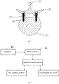
- Fig. 3 is a structural schematic diagram for fixing a broken vertebral pedicle with an implantation device in some embodiments of the present disclosure.
- the operation system for bone tissue 1 shown in Fig. 2 includes a master control unit 11 and an implantation mechanical arm 12, a first implantation device 13 and a second implantation device 14 which are communication connection with the master control unit 11.
- the first implantation device 13 and the second implantation device 14 constitute an implantation device 24.
- a first vertebral segment 22 and a second vertebral segment 23 are separated by a space 25.
- the master control unit 11 controls the implantation mechanical arm 12 to clamp the first implantation device 13 to penetrate the first vertebral segment 22 and to be fixedly connected to same, so as to form a spacing distance between the first vertebral segment 22 and the second vertebral segment 23 and guarantee accuracy of the spacing distance, and further the master control unit controls the implantation mechanical arm 12 to clamp the second implantation device 14 to penetrate the first implantation device 13 and to be fixedly connected to same and the second vertebral segment 23.
- the implantation mechanical arm is provided with a clamping structure to adapt to the first implantation device and the second implantation device.
- the method before the location step is performed, the method further includes a preoperative path planning step.
- the preoperative path planning step includes:
- Fig. 4 is a structural block diagram of a second operation system for bone tissue in an embodiment of the present disclosure.
- the operation system for bone tissue shown in Fig. 4 differs from the operation system for bone tissue 1 shown in Fig. 2 in that the operation system for bone tissue shown in Fig. 4 further includes a storage portion 31 in communication connection with the master control unit 11, and the storage portion 31 stores spacing distance range reference data.
- the master control unit 11 calls the spacing distance range reference data from the storage unit 31 to control the spacing distance to conform to the spacing distance range reference data, so as to guarantee accuracy of the actual spacing distance.
- the master control unit 11 stores the spacing distance range reference data, that is, the storage unit 31 is a constituent structure in the master control unit 11.
- Fig. 5 is a structural block diagram of a third operation system for bone tissue in an embodiment of the present disclosure.
- the operation system for bone tissue shown in Fig. 5 differs from that shown in Fig. 4 in that the operation system for bone tissue shown in Fig. 5 further includes an auxiliary image device 41 in communication connection with the master control unit 11.
- the auxiliary image device 41 acquires real-time location information of the first vertebral segment 22 and the second vertebral segment 23 and feeds same back to the master control unit 11.
- the master control unit 11 determines whether the spacing distance conforms to the spacing distance range reference data according to the real-time location information, thus guaranteeing the accuracy of the spacing distance.
- the auxiliary image device 41 is a C-arm X-ray machine or a computed tomography (CT) apparatus to acquire image information of target bone tissue.
- CT computed tomography
- the hollowed structure during movement of the hollowed structure towards the second vertebral segment, is controlled to face the end face of the second vertebral segment and keep surface contact with the second vertebral segment, thereby avoiding damage to a post-osteotomy section.
- the hollowed structure in the location step in S1, is caused to face the end face of the second vertebral segment and make planar contact or spherical contact with the second vertebral segment, thereby avoiding damage to the post-osteotomy section.
- the first implantation device includes a nut structure provided with internal threads and external nut threads
- the second implantation device includes a screw structure provided with external threads
- the external threads adapt to the internal threads.
- a bottom of the nut structure includes a nut contact surface, such that in the location step in S1, the hollowed structure is caused to face the end face of the second vertebral segment and make planar contact or spherical contact with the second vertebral segment, thereby avoiding damage to the post-osteotomy section.
- Fig. 6 is a structural schematic diagram showing a nut structure acting on a first vertebral segment in some embodiments of the present disclosure
- Fig. 7 is an enlarged structural schematic diagram of portion A shown in Fig. 6 .
- the master control unit 11 controls, by means of the implantation mechanical arm 12, the nut structure 51 to penetrate the first vertebral segment 22, and pass through space 25 to make surface contact with the second vertebral segment 23 to form the spacing distance and be fixedly connected to the first vertebral segment 22.
- the bottom of the nut structure 51 makes surface contact with a top surface of the second vertebral segment 23.
- the spacing distance between the first vertebral segment 22 and the second vertebral segment 23 is an average of several vertical distances from a bottom of the first vertebral segment 22 to the top surface of the second vertebral segment 23.
- the clamping structure of the implantation mechanical arm includes a casing structure, a stretchable structure accommodated in the casing structure and a lock structure in movable contact with the stretchable structure, the casing structure being detachably and fixedly connected to the first implantation device, and the stretchable structure stretching out to push out the lock structure to abut against an inner wall of the first implantation device, such that the clamping structure of the implantation mechanical arm may be detachably and fixedly connected to the first implantation device, movement of the first implantation device may be conveniently controlled by means of the clamping structure of the implantation mechanical arm in a more accurate manner, which is conducive to movement stability of the first implantation device during implantation.
- a top of the first implantation device is provided with an accommodation structure, at least a portion of the lock structure pushed out as the stretchable structure stretches out is accommodated in the accommodation structure, the accommodation structure is arranged to accommodate the lock structure, such that firmness of abutting connection between the lock structure and the first implantation device may be better guaranteed, the clamping structure of the implantation mechanical arm may be connected and fixed to the first implantation device more conveniently, and subsequent operations may be facilitated accordingly.
- the clamping structure of the implantation mechanical arm further includes an electromagnetic control portion electrically connected to the stretchable structure, and the electromagnetic control portion controls the lock structure to enter or exit the accommodation structure by controlling the stretchable structure to move towards or away from the first implantation device, such that accurate control is facilitated to a higher extent and higher operation flexibility is achieved.
- the lock structure includes several ball structure relatively attracted to two sides of the stretchable structure.
- the electromagnetic control portion controls the stretchable structure to move towards the first implantation device
- a portion of the stretchable structure is accommodated in the top of the first implantation device, and the several ball structures enter the accommodation structure from the two sides of the stretchable structure and contact with the stretchable structure to compress the stretchable structure.
- the accommodation structure is arranged in a radial direction of the first implantation device, and an axial length inner diameter of the accommodation structure is smaller than a maximum axial length of the lock structure, such that firmness of abutting connection between the lock structure and the first implantation device may be better guaranteed, the clamping structure of the implantation mechanical arm may be connected and fixed to the first implantation device more conveniently, and subsequent operations may be facilitated accordingly.
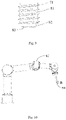
- Fig. 8 is a schematic diagram of the nut structure shown in Fig. 6 and Fig. 9 is a structural schematic diagram of a bottom of the nut structure shown in Fig. 8 .
- an outer side wall of a nut body 81 of the nut structure 51 is provided with nut external threads 71, which is conducive to fixed connection between the nut structure 51 and the first vertebral segment 22 after the expansion distance is formed.
- An inner side wall of the nut structure 51 is provided with internal threads 72 to adapt to the second implantation device.
- a top of the nut structure 51 is provided with an accommodation structure 73 to adapt to the implantation mechanical arm 12.
- a free end of the nut structure 51 converges towards an axis (not shown in the figure) of the nut structure to cause a portion of an outer side wall of the nut structure 51 to be arc-shaped, thereby reducing a friction effect of the surface contact between the nut structure 51 and the second vertebral segment 23.
- the bottom of the nut body 81 includes a boss 82, an outer diameter of the boss 82 is smaller than an outer diameter of the nut body 81, and a free end edge of the boss 82 is provided with a rounded structure 83, so as to cause the portion of the outer side wall of the nut structure 51 to be arc-shaped.
- a height of the boss 82 is the expansion distance.
- Fig. 10 is a schematic diagram of an operation state in which an implantation mechanical arm clamps the nut structure in some embodiments of the present disclosure.
- Fig. 11 is an enlarged structural schematic diagram of portion B shown in Fig. 10 .
- the implantation mechanical arm 12 is a six-axis mechanical arm.
- the clamping structure of the implantation mechanical arm 12 includes the casing structure 101, the stretchable structure 103 accommodated in the casing structure, and a lock structure 102 in movable contact with the stretchable structure 103.
- the casing structure 101 is in clearance fit with a cavity of the nut structure 51, that is, the casing structure 101 may be movably inserted into the cavity of the nut structure 51.
- the casing structure is further internally provided with a channel 104 allowing the stretchable structure 103 to stretch out and draw back, and the top of the nut structure 51 is provided with the accommodation structure 73.
- the stretchable structure 103 is electrically connected to the electromagnetic control portion 105.
- the accommodation structure 73 is arranged in a radial direction of the nut structure 51. Specifically, an inner diameter of the accommodation structure 73 is smaller than a diameter of the ball structure 102.
- the stretchable structure 103 and the electromagnetic control portion 105 constitute an electromagnetic bolt.
- the electromagnetic control portion 105 causes the stretchable structure 103 to be accommodated in the casing structure 101 when not energized, and the two ball structures 102 are attracted to the bottom of the casing structure 101.
- the bottom of the casing structure 101 is accommodated in the top of the nut structure 51, and after the electromagnetic control portion 105 is energized, the stretchable structure 103 stretches out of the bottom of the casing structure 101 and moves towards the bottom of the nut structure 51 under the action of electromagnetic attraction. Since the inner diameter of the accommodation channel 73 is smaller than the diameter of the ball structure 102, after one portions of the two ball structures 102 are squeezed into the accommodation structure 73, the other portions clamp the stretchable structure 103 on the opposite sides of the stretchable structure 103, thus clamping and fixing the nut structure 51.
- the accommodation structure penetrates the top of the nut structure, such that a penetrated structure is formed, and a process is simple and machining is more convenient.
- the second implantation device 14 includes the screw structure.
- Fig. 12 is a structural schematic diagram for showing a screw structure acting on the nut structure and a second vertebral segment in some embodiments of the present disclosure
- Fig. 13 is a schematic diagram of the screw structure shown in Fig. 12
- the implantation mechanical arm 12 controls the screw structure 111 to be implanted into the second vertebral segment 23 by means of the nut structure 51.
- the screw structure 111 is provided with the external threads 121 to adapt to the internal threads (not shown in the figure) of the nut structure 51.
- the screw structure 111 has a bottom in a pointed structure 123, so as to be smoothly screwed into the second vertebral segment 23.
- the screw structure 111 may be fixedly connected to the second vertebral segment 23 and the nut structure 51, such that the first vertebral segment 22 and the second vertebral segment 23 may be fixed.
- a top of the screw structure 111 is provided with a screw accommodation structure 122 with the same structure as that of the accommodation structure, so as to accommodate the lock structure and to be detachably and fixedly connected to the casing structure, such that the clamping structure of the implantation mechanical arm may be detachably and fixedly connected to the screw structure, and movement of the screw structure may be conveniently controlled by means of the clamping structure of the implantation mechanical arm in a more accurate manner, which is conducive to movement stability of the screw structure during implantation.
- an ultrasonic osteotome is used to act on the target bone tissue to form the space.
- the vertebral pedicle 21 forms the first vertebral segment 22 and the second vertebral segment 23, and then the implantation device 24 penetrates the first vertebral segment 22, and passes through the space 25 to be fixed to the second vertebral segment 23.
- the operation system for bone tissue further includes an osteotomy device for acting on target bone tissue to form a space.
- the operation system for bone tissue further includes the master control unit and the osteotomy mechanical arm clamping the osteotomy device, where the master control unit is in communication connection with the osteotomy mechanical arm, and the osteotomy device includes an actuator clamped at a free end of the osteotomy mechanical arm, and the master control unit controls the osteotomy mechanical arm to cause the actuator to act on the target bone tissue to form the space.
- Fig. 14 is a structural block diagram of a fourth operation system for bone tissue in an embodiment of the present disclosure.
- the operation system for bone tissue shown in Fig. 14 differs from the operation system for bone tissue 1 shown in Fig. 2 is that the operation system for bone tissue shown in Fig. 14 further includes an osteotomy mechanical arm 131 which is in communication connection with a master control unit 11 and holds an osteotomy device 132, and the master control unit 11 controls the osteotomy mechanical arm 131 to cause the osteotomy device 132 to form a space 25 at a vertebral pedicle 21.
- the osteotomy device 132 includes an actuator to clamp a free end of the osteotomy mechanical arm 131 and act on target bone tissue.
- the actuator includes an ultrasonic osteotome.
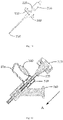
- Fig. 15 is a structural schematic diagram of an osteotomy device in an embodiment of the present disclosure.
- Fig. 16 is a sectional view of a portion of the structure shown in Fig. 15 .
- the osteotomy device shown in Fig. 15 includes an actuator 210 and a buffer mechanism (not shown in the figure), and the buffer mechanism (not shown in the figure) partially sleeves the actuator 210.
- the buffer structure (not shown in the figure) is composed of a pressure sensing portion 220 and a buffer drive portion 230, and the buffer drive portion 230 is fixed to the actuator 210 in a sleeving manner.
- the pressure sensing portion 220 is arranged on the actuator 210.
- the buffer mechanism acts on the actuator 210 according to detected change of the pressure by the actuator 210 acting on the target bone tissue.
- the actuator 210 acts on the target bone tissue (not shown in the figure) in the operation direction, that is, an A direction shown in Fig. 16 , and the pressure sensing portion 220 detects that the change of the pressure by the actuator 210 acting on the target bone tissue is a stable pressure condition, and feeds the stable pressure condition back to the buffer drive portion 230.
- the buffer drive portion 230 assists the actuator 210 in strengthening the action on the target bone tissue (not shown in the figure), that is, the buffer mechanism drives the actuator 210 to move in the A direction to act on the target bone tissue (not shown in the figure).
- the stable pressure condition means that a pressure value remains unchanged within a certain period of time or within a certain pressure control range, which indicates that the actuator 210 continuously and stably acts on the target bone tissue. Since the buffer drive portion 230 is fixed to the actuator 210 in a sleeving manner, the buffer drive portion may follow movement of the actuator 210 to stabilize the action on the target bone tissue (not shown in the figure).
- the actuator 210 acts on the target bone tissue (not shown in the figure) in the A direction shown in Fig. 16 , and the pressure sensing portion 220 detects that the change of the pressure by the actuator 210 acting on the target bone tissue is a sudden pressure fall condition, and feeds the sudden pressure fall condition back to the buffer drive portion 230.
- the buffer drive portion 230 produces reverse thrust in a direction opposite the A direction to weaken the action of the actuator 210 on the target bone tissue (not shown in the figure), thereby reducing the risk of nerve and blood vessel damage due to overshoot during osteotomy.
- the sudden pressure fall is that the pressure produced by the actuator 210 acting on the target bone tissue is reduced to a minimum value in a first period, that is, that is, the pressure acting on the target bone tissue at the moment when the actuator 210 cuts off the target bone tissue may be attenuated to zero or close to zero, and at this time, it is necessary to reduce the risk of nerve and blood vessel damage by means of the reverse thrust of the buffer drive portion 230 on the actuator 210.
- the minimum value is 0, and the first period is no longer than 0.1 s.
- Fig. 17 is a partial structural schematic diagram of a buffer drive portion shown in Fig. 15 .
- the buffer drive portion 230 includes a closed cavity 420 and a drive portion 410 penetrating the closed cavity 420, the drive portion 410 divides the closed cavity 420 into a first cavity 430 and a second cavity 440, the first cavity 430 is close to an actuation end 250 of the actuator 210, and the second cavity 440 is far away from the actuation end 250 of the actuator 210.
- the buffer drive portion 230 further includes a duct portion 330 and an opening and closing control portion (not shown in the figure) which is arranged in the duct portion 330 and in communication connection with the pressure sensing portion 220, the duct portion 330 is arranged in the closed cavity 420 and is in communication connection with the first cavity 430 and the second cavity 440 separately, the opening and closing control portion (not shown in the figure) is composed of a control portion (not shown in the figure) and an opening and closing portion 340 which are in communication connection, and the control portion (not shown in the figure) is in communication connection with the pressure sensing portion 220.
- control portion (not shown in the figure) is a computer control system.
- the opening and closing portion 340 is an electromagnetic valve.
- the pressure sensing portion 220 is a force sensor.
- the opening and closing control portion controls the opening and closing portion 340 to close communication of the duct portion 330 with the first cavity 430 and the second cavity 440, such that the drive portion 410 produces the reverse thrust on the actuator 210 in the direction opposite the operation direction to weaken the action of the actuator 210 on the target bone tissue.
- both the first cavity 430 and the second cavity 440 contain hydraulic media.
- the opening and closing portion 340 opens the communication of the duct portion 330 with the first cavity 430 and the second cavity 440, the hydraulic media is transferred between the first cavity 430 and the second cavity 440 by means of the duct portion 330.
- the hydraulic medium is hydraulic oil.
- the buffer drive portion 230 moves along with the actuator 210 in the operation direction to expand a volume in the second cavity 440 and compress a volume in the first cavity 430, in addition, since the volume in the first cavity 430 is compressed, the hydraulic medium therein flows into the second cavity 440 by means of the duct portion 330 to further compress the volume in the first cavity 430, thereby assisting the actuator 210 in moving further in the operation direction to act on the target bone tissue.
- the control portion controls the opening and closing portion 340 to close the communication of the duct portion 330 with the first cavity 430 and the second cavity 440, such that the hydraulic medium may not transfer between the first cavity 430 and the second cavity 440.
- the hydraulic medium flows into the second cavity 440 by means of the duct portion 330 to further compress the volume in the first cavity 430.
- a pressure in the first cavity 430 is greater than that in the second cavity 440, so as to produce the reverse thrust in the direction opposite the operation direction on the drive portion 410, then push the actuator 210 to move in the direction opposite the operation direction or stop the actuator 210 from moving, and weaken the action of the actuator 210 on the target bone tissue.
- the drive portion 410 includes a division portion 470, and an outer side wall of the division portion 470 is attached to an inner side wall of the closed cavity 420, such that division portion moves relative to the closed cavity 420 and divides the closed cavity 420 to form the first cavity 430 and the second cavity 440.
- the drive portion 410 further includes a hollowed shaft part to penetrate and be fixedly connected to the division portion 470, and penetrate and be movably connected to the closed cavity 420.
- seal structures are arranged at a joint and an attachment portion between the drive portion 410 and the closed cavity 420.
- a first seal structure 460 is arranged at the joint of the drive portion 410 and the closed cavity 420 to enhance a sealing effect on the closed cavity 420.
- the outer side wall of the division portion 470 is provided with a second seal structure 450 to attach to the closed cavity 420 and further enhance respective sealing of the first cavity 430 and the second cavity 440.
- first seal structure 460 and the second seal structure 450 are both seal rings.
- the osteotomy device shown in Fig. 15 further includes an observation portion 240 to monitor the action of the actuator 210 on the target bone tissue (not shown in the figure).
- the observation portion 240 is fixedly connected to the drive portion 410, and the actuator 210 moves through the observation portion 240.
- the observation portion 240 is an arthroscope with a hollowed structure.
- the osteotomy device further includes an ultrasonic generator in communication connection with the actuator, such that an actuation end 250 of the actuator 210 acts on the target bone tissue in a high-frequency resonance mode.
- the ultrasonic generator and the actuator 210 together constitute the ultrasonic osteotome.
- the osteotomy device further includes a movable support portion movably connected to the observation portion 240 to adjust an orientation of the observation portion.
- a degree of freedom of motion of the movable support portion is 7, such that the orientation of the observation portion may be adjusted at will.
- the movable support portion includes a rotary joint portion and a plurality of ball joint portions.
- the operation system for bone tissue further includes a master control unit and several mechanical arms, where the master control unit is in communication connection with the mechanical arms, and the several mechanical arms are in an identical structure or different structures.
- the operation system for bone tissue has the beneficial effects as follows: the number of mechanical arms may be increased according to the requirements from implantation, osteotomy or other functional operations, and various use requirements may be met.
- Fig. 18 is a structural schematic diagram of another osteotomy device in an embodiment of the present disclosure.
- the osteotomy device shown in Fig. 18 differs from the osteotomy device shown in Fig. 15 in that the osteotomy device shown in Fig. 18 further includes a rotary joint portion consisting of a first rod portion 510 and a second rod portion 530 which are movably connected, and a first ball joint portion 540 and a second ball joint portion 550 which are arranged at two ends of the rotary joint portion, and the first ball joint portion 540 is movably connected to the observation portion 240 to adjust the orientation of the observation portion 240.
- a joint location of the rotary joint is movably connected to a locking portion for adjusting a relative location between the rotary joint portion and the observation portion 240.
- the locking portion 520 is provided at the joint of the first rod portion 510 and the second rod portion 530.
- the locking portion 520 is not locked, such that the observation portion 240 and the actuator 210 may move flexibly to find a location where osteotomy is required.
Landscapes
- Health & Medical Sciences (AREA)
- Life Sciences & Earth Sciences (AREA)
- Surgery (AREA)
- Orthopedic Medicine & Surgery (AREA)
- Engineering & Computer Science (AREA)
- Molecular Biology (AREA)
- Veterinary Medicine (AREA)
- Biomedical Technology (AREA)
- Heart & Thoracic Surgery (AREA)
- Medical Informatics (AREA)
- Nuclear Medicine, Radiotherapy & Molecular Imaging (AREA)
- Animal Behavior & Ethology (AREA)
- General Health & Medical Sciences (AREA)
- Public Health (AREA)
- Neurology (AREA)
- Robotics (AREA)
- Oral & Maxillofacial Surgery (AREA)
- Human Computer Interaction (AREA)
- Dentistry (AREA)
- Pathology (AREA)
- Surgical Instruments (AREA)
- Prostheses (AREA)
Priority Applications (1)
| Application Number | Priority Date | Filing Date | Title |
|---|---|---|---|
| EP24167106.4A EP4389054B1 (fr) | 2021-06-02 | 2021-06-02 | Système d'opération pour tissu osseux |
Applications Claiming Priority (1)
| Application Number | Priority Date | Filing Date | Title |
|---|---|---|---|
| PCT/CN2021/097895 WO2022252147A1 (fr) | 2021-06-02 | 2021-06-02 | Méthode chirurgicale de tissu osseux et système chirurgical de tissu osseux |
Related Child Applications (2)
| Application Number | Title | Priority Date | Filing Date |
|---|---|---|---|
| EP24167106.4A Division EP4389054B1 (fr) | 2021-06-02 | 2021-06-02 | Système d'opération pour tissu osseux |
| EP24167106.4A Division-Into EP4389054B1 (fr) | 2021-06-02 | 2021-06-02 | Système d'opération pour tissu osseux |
Publications (3)
| Publication Number | Publication Date |
|---|---|
| EP4119076A1 true EP4119076A1 (fr) | 2023-01-18 |
| EP4119076A4 EP4119076A4 (fr) | 2023-08-16 |
| EP4119076B1 EP4119076B1 (fr) | 2024-05-15 |
Family
ID=84322677
Family Applications (2)
| Application Number | Title | Priority Date | Filing Date |
|---|---|---|---|
| EP24167106.4A Active EP4389054B1 (fr) | 2021-06-02 | 2021-06-02 | Système d'opération pour tissu osseux |
| EP21925118.8A Active EP4119076B1 (fr) | 2021-06-02 | 2021-06-02 | Système chirurgical de tissu osseux |
Family Applications Before (1)
| Application Number | Title | Priority Date | Filing Date |
|---|---|---|---|
| EP24167106.4A Active EP4389054B1 (fr) | 2021-06-02 | 2021-06-02 | Système d'opération pour tissu osseux |
Country Status (3)
| Country | Link |
|---|---|
| US (1) | US20240197370A1 (fr) |
| EP (2) | EP4389054B1 (fr) |
| WO (1) | WO2022252147A1 (fr) |
Family Cites Families (22)
| Publication number | Priority date | Publication date | Assignee | Title |
|---|---|---|---|---|
| US6358254B1 (en) | 2000-09-11 | 2002-03-19 | D. Greg Anderson | Method and implant for expanding a spinal canal |
| US7708766B2 (en) * | 2003-08-11 | 2010-05-04 | Depuy Spine, Inc. | Distraction screw |
| US9949843B2 (en) * | 2004-08-09 | 2018-04-24 | Si-Bone Inc. | Apparatus, systems, and methods for the fixation or fusion of bone |
| AU2007254159B2 (en) * | 2006-05-19 | 2013-07-04 | Mako Surgical Corp. | System and method for verifying calibration of a surgical device |
| JP5154572B2 (ja) * | 2006-12-15 | 2013-02-27 | ザ エーデルマン リサーチ リミテッド | 椎弓截骨術及び椎弓形成術の方法及びデバイス |
| CA2739431C (fr) * | 2008-10-01 | 2016-12-06 | Sherwin Hua | Systeme et procede de stabilisation de vertebres spinales par vis pediculaires guidees par fils |
| EP3560445A1 (fr) * | 2010-03-30 | 2019-10-30 | Sherwin Hua | Systèmes pour la stabilisation par vis pédiculaire de vertèbres spinales |
| EP3656317A1 (fr) * | 2011-09-02 | 2020-05-27 | Stryker Corporation | Système chirurgical comprenant un instrument et procédé d'utilisation de l'instrument |
| SG11201401672QA (en) * | 2011-10-21 | 2014-09-26 | Innovative Surgical Designs Inc | Surgical implants for percutaneous lengthening of spinal pedicles to correct spinal stenosis |
| US10016220B2 (en) * | 2011-11-01 | 2018-07-10 | Nuvasive Specialized Orthopedics, Inc. | Adjustable magnetic devices and methods of using same |
| US11395706B2 (en) * | 2012-06-21 | 2022-07-26 | Globus Medical Inc. | Surgical robot platform |
| EP2863827B1 (fr) * | 2012-06-21 | 2022-11-16 | Globus Medical, Inc. | Plateforme de robot chirurgical |
| US10624710B2 (en) * | 2012-06-21 | 2020-04-21 | Globus Medical, Inc. | System and method for measuring depth of instrumentation |
| US10245087B2 (en) * | 2013-03-15 | 2019-04-02 | Jcbd, Llc | Systems and methods for fusing a sacroiliac joint and anchoring an orthopedic appliance |
| US9743936B2 (en) * | 2014-03-11 | 2017-08-29 | Minmaxmedical | Surgical osteotomy method, a method of control of a computer piloted robot and a surgical system for implementing such a surgical method |
| EP3123970B1 (fr) * | 2015-07-31 | 2018-04-18 | Lechoslaw Franciszek Ciupik | Stabilisation de deux os adjacents |
| US9949774B2 (en) * | 2016-05-26 | 2018-04-24 | Timothy Chen | Axial compression implant |
| US10463404B2 (en) * | 2017-07-27 | 2019-11-05 | Warsaw Orthopedic, Inc. | Spinal implant system and method |
| FR3072559B1 (fr) * | 2017-10-24 | 2023-03-24 | Spineguard | Systeme medical comprenant un bras robotise et un dispositif medical destine a penetrer dans une structure anatomique |
| EP3705069B1 (fr) * | 2019-03-05 | 2023-02-22 | K2M, Inc. | Tournevis à cliquet automatique |
| CN110313983B (zh) * | 2019-07-23 | 2024-12-06 | 天津正天医疗器械有限公司 | 一种定位钉植入器 |
| US10743919B1 (en) * | 2019-11-12 | 2020-08-18 | Seth K. WILLIAMS | Navigated percutaneous lumbar and thoracic spine facet fusion |
-
2021
- 2021-06-02 EP EP24167106.4A patent/EP4389054B1/fr active Active
- 2021-06-02 US US17/791,405 patent/US20240197370A1/en not_active Abandoned
- 2021-06-02 WO PCT/CN2021/097895 patent/WO2022252147A1/fr not_active Ceased
- 2021-06-02 EP EP21925118.8A patent/EP4119076B1/fr active Active
Also Published As
| Publication number | Publication date |
|---|---|
| EP4389054A3 (fr) | 2024-08-14 |
| EP4119076B1 (fr) | 2024-05-15 |
| US20240197370A1 (en) | 2024-06-20 |
| WO2022252147A1 (fr) | 2022-12-08 |
| EP4389054A2 (fr) | 2024-06-26 |
| EP4389054B1 (fr) | 2025-09-10 |
| EP4119076A4 (fr) | 2023-08-16 |
Similar Documents
| Publication | Publication Date | Title |
|---|---|---|
| US12295630B2 (en) | Adjustable devices for treating arthritis of the knee | |
| US12446925B2 (en) | Orthopedic growing devices | |
| EP3054872B1 (fr) | Procédés et appareil pour le refaçonnage osseux | |
| KR20180067632A (ko) | 무릎의 관절염을 치료하기 위한 조정 가능한 장치 | |
| JP2019505354A (ja) | 動的安定化椎間インプラントおよびそれを備える手術用キット | |
| US11806057B2 (en) | System and method for surgical implant positioning and fixation | |
| JP2019531862A (ja) | 自己作動成長ロッドシステム | |
| EP4119076A1 (fr) | Méthode chirurgicale de tissu osseux et système chirurgical de tissu osseux | |
| CN112618234A (zh) | 一种辅助机器人脊柱微创手术定位的手术床及其定位方法 | |
| EP4175571B1 (fr) | Dispositif pour clou osseux | |
| CN212522048U (zh) | 一种基于核磁共振引导的乳腺组织固定装置 | |
| US20240050130A1 (en) | Constant distraction force driven self actuating growing rod systems | |
| CN113288436B (zh) | 骨组织手术系统 | |
| CN113288328B (zh) | 截骨手术器械 | |
| CN114027963A (zh) | 基于定位点的骶髂关节螺钉定位辅助结构及置入方法 | |
| CN119587155B (zh) | 一种远程控制的骨盆骨折复位系统 | |
| CN121926671A (zh) | 一种用于早中期股骨头坏死治疗的骨牵张器械 | |
| RU2206286C2 (ru) | Способ вправления застарелых вывихов плечевой кости | |
| Jiang | Clinical Progress of Minimally Invasive Treatment of Pelvic Fractures with Orthopedic Robotic Navigation System | |
| HK40090318B (en) | Bone nail device | |
| HK40090318A (en) | Bone nail device |
Legal Events
| Date | Code | Title | Description |
|---|---|---|---|
| STAA | Information on the status of an ep patent application or granted ep patent |
Free format text: STATUS: UNKNOWN |
|
| STAA | Information on the status of an ep patent application or granted ep patent |
Free format text: STATUS: THE INTERNATIONAL PUBLICATION HAS BEEN MADE |
|
| PUAI | Public reference made under article 153(3) epc to a published international application that has entered the european phase |
Free format text: ORIGINAL CODE: 0009012 |
|
| STAA | Information on the status of an ep patent application or granted ep patent |
Free format text: STATUS: REQUEST FOR EXAMINATION WAS MADE |
|
| 17P | Request for examination filed |
Effective date: 20220819 |
|
| AK | Designated contracting states |
Kind code of ref document: A1 Designated state(s): AL AT BE BG CH CY CZ DE DK EE ES FI FR GB GR HR HU IE IS IT LI LT LU LV MC MK MT NL NO PL PT RO RS SE SI SK SM TR |
|
| RIN1 | Information on inventor provided before grant (corrected) |
Inventor name: WANG, SHAOBAI |
|
| RIC1 | Information provided on ipc code assigned before grant |
Ipc: A61B 34/37 20160101ALI20230404BHEP Ipc: A61B 90/00 20160101ALI20230404BHEP Ipc: A61B 17/88 20060101ALI20230404BHEP Ipc: A61B 17/86 20060101ALI20230404BHEP Ipc: A61B 17/32 20060101ALI20230404BHEP Ipc: A61B 17/70 20060101ALI20230404BHEP Ipc: A61B 17/16 20060101ALI20230404BHEP Ipc: A61B 34/30 20160101ALI20230404BHEP Ipc: A61B 17/68 20060101AFI20230404BHEP |
|
| A4 | Supplementary search report drawn up and despatched |
Effective date: 20230713 |
|
| RIC1 | Information provided on ipc code assigned before grant |
Ipc: A61B 34/37 20160101ALI20230707BHEP Ipc: A61B 90/00 20160101ALI20230707BHEP Ipc: A61B 17/88 20060101ALI20230707BHEP Ipc: A61B 17/86 20060101ALI20230707BHEP Ipc: A61B 17/32 20060101ALI20230707BHEP Ipc: A61B 17/70 20060101ALI20230707BHEP Ipc: A61B 17/16 20060101ALI20230707BHEP Ipc: A61B 34/30 20160101ALI20230707BHEP Ipc: A61B 17/68 20060101AFI20230707BHEP |
|
| DAV | Request for validation of the european patent (deleted) | ||
| DAX | Request for extension of the european patent (deleted) | ||
| GRAP | Despatch of communication of intention to grant a patent |
Free format text: ORIGINAL CODE: EPIDOSNIGR1 |
|
| STAA | Information on the status of an ep patent application or granted ep patent |
Free format text: STATUS: GRANT OF PATENT IS INTENDED |
|
| INTG | Intention to grant announced |
Effective date: 20240118 |
|
| GRAS | Grant fee paid |
Free format text: ORIGINAL CODE: EPIDOSNIGR3 |
|
| GRAA | (expected) grant |
Free format text: ORIGINAL CODE: 0009210 |
|
| STAA | Information on the status of an ep patent application or granted ep patent |
Free format text: STATUS: THE PATENT HAS BEEN GRANTED |
|
| RAP3 | Party data changed (applicant data changed or rights of an application transferred) |
Owner name: SHANGHAI DROIDSURG MEDICAL CO., LTD |
|
| AK | Designated contracting states |
Kind code of ref document: B1 Designated state(s): AL AT BE BG CH CY CZ DE DK EE ES FI FR GB GR HR HU IE IS IT LI LT LU LV MC MK MT NL NO PL PT RO RS SE SI SK SM TR |
|
| REG | Reference to a national code |
Ref country code: CH Ref legal event code: EP |
|
| REG | Reference to a national code |
Ref country code: IE Ref legal event code: FG4D |
|
| REG | Reference to a national code |
Ref country code: DE Ref legal event code: R096 Ref document number: 602021013428 Country of ref document: DE |
|
| REG | Reference to a national code |
Ref country code: LT Ref legal event code: MG9D |
|
| REG | Reference to a national code |
Ref country code: NL Ref legal event code: MP Effective date: 20240515 |
|
| PG25 | Lapsed in a contracting state [announced via postgrant information from national office to epo] |
Ref country code: IS Free format text: LAPSE BECAUSE OF FAILURE TO SUBMIT A TRANSLATION OF THE DESCRIPTION OR TO PAY THE FEE WITHIN THE PRESCRIBED TIME-LIMIT Effective date: 20240915 |
|
| PG25 | Lapsed in a contracting state [announced via postgrant information from national office to epo] |
Ref country code: BG Free format text: LAPSE BECAUSE OF FAILURE TO SUBMIT A TRANSLATION OF THE DESCRIPTION OR TO PAY THE FEE WITHIN THE PRESCRIBED TIME-LIMIT Effective date: 20240515 |
|
| PG25 | Lapsed in a contracting state [announced via postgrant information from national office to epo] |
Ref country code: HR Free format text: LAPSE BECAUSE OF FAILURE TO SUBMIT A TRANSLATION OF THE DESCRIPTION OR TO PAY THE FEE WITHIN THE PRESCRIBED TIME-LIMIT Effective date: 20240515 Ref country code: FI Free format text: LAPSE BECAUSE OF FAILURE TO SUBMIT A TRANSLATION OF THE DESCRIPTION OR TO PAY THE FEE WITHIN THE PRESCRIBED TIME-LIMIT Effective date: 20240515 |
|
| PG25 | Lapsed in a contracting state [announced via postgrant information from national office to epo] |
Ref country code: GR Free format text: LAPSE BECAUSE OF FAILURE TO SUBMIT A TRANSLATION OF THE DESCRIPTION OR TO PAY THE FEE WITHIN THE PRESCRIBED TIME-LIMIT Effective date: 20240816 |
|
| PG25 | Lapsed in a contracting state [announced via postgrant information from national office to epo] |
Ref country code: PT Free format text: LAPSE BECAUSE OF FAILURE TO SUBMIT A TRANSLATION OF THE DESCRIPTION OR TO PAY THE FEE WITHIN THE PRESCRIBED TIME-LIMIT Effective date: 20240916 |
|
| REG | Reference to a national code |
Ref country code: AT Ref legal event code: MK05 Ref document number: 1686270 Country of ref document: AT Kind code of ref document: T Effective date: 20240515 |
|
| PG25 | Lapsed in a contracting state [announced via postgrant information from national office to epo] |
Ref country code: NL Free format text: LAPSE BECAUSE OF FAILURE TO SUBMIT A TRANSLATION OF THE DESCRIPTION OR TO PAY THE FEE WITHIN THE PRESCRIBED TIME-LIMIT Effective date: 20240515 |
|
| PG25 | Lapsed in a contracting state [announced via postgrant information from national office to epo] |
Ref country code: ES Free format text: LAPSE BECAUSE OF FAILURE TO SUBMIT A TRANSLATION OF THE DESCRIPTION OR TO PAY THE FEE WITHIN THE PRESCRIBED TIME-LIMIT Effective date: 20240515 |
|
| PG25 | Lapsed in a contracting state [announced via postgrant information from national office to epo] |
Ref country code: AT Free format text: LAPSE BECAUSE OF FAILURE TO SUBMIT A TRANSLATION OF THE DESCRIPTION OR TO PAY THE FEE WITHIN THE PRESCRIBED TIME-LIMIT Effective date: 20240515 |
|
| PG25 | Lapsed in a contracting state [announced via postgrant information from national office to epo] |
Ref country code: PL Free format text: LAPSE BECAUSE OF FAILURE TO SUBMIT A TRANSLATION OF THE DESCRIPTION OR TO PAY THE FEE WITHIN THE PRESCRIBED TIME-LIMIT Effective date: 20240515 |
|
| PG25 | Lapsed in a contracting state [announced via postgrant information from national office to epo] |
Ref country code: LV Free format text: LAPSE BECAUSE OF FAILURE TO SUBMIT A TRANSLATION OF THE DESCRIPTION OR TO PAY THE FEE WITHIN THE PRESCRIBED TIME-LIMIT Effective date: 20240515 |
|
| PG25 | Lapsed in a contracting state [announced via postgrant information from national office to epo] |
Ref country code: PT Free format text: LAPSE BECAUSE OF FAILURE TO SUBMIT A TRANSLATION OF THE DESCRIPTION OR TO PAY THE FEE WITHIN THE PRESCRIBED TIME-LIMIT Effective date: 20240916 Ref country code: PL Free format text: LAPSE BECAUSE OF FAILURE TO SUBMIT A TRANSLATION OF THE DESCRIPTION OR TO PAY THE FEE WITHIN THE PRESCRIBED TIME-LIMIT Effective date: 20240515 Ref country code: NO Free format text: LAPSE BECAUSE OF FAILURE TO SUBMIT A TRANSLATION OF THE DESCRIPTION OR TO PAY THE FEE WITHIN THE PRESCRIBED TIME-LIMIT Effective date: 20240815 Ref country code: NL Free format text: LAPSE BECAUSE OF FAILURE TO SUBMIT A TRANSLATION OF THE DESCRIPTION OR TO PAY THE FEE WITHIN THE PRESCRIBED TIME-LIMIT Effective date: 20240515 Ref country code: LV Free format text: LAPSE BECAUSE OF FAILURE TO SUBMIT A TRANSLATION OF THE DESCRIPTION OR TO PAY THE FEE WITHIN THE PRESCRIBED TIME-LIMIT Effective date: 20240515 Ref country code: IS Free format text: LAPSE BECAUSE OF FAILURE TO SUBMIT A TRANSLATION OF THE DESCRIPTION OR TO PAY THE FEE WITHIN THE PRESCRIBED TIME-LIMIT Effective date: 20240915 Ref country code: HR Free format text: LAPSE BECAUSE OF FAILURE TO SUBMIT A TRANSLATION OF THE DESCRIPTION OR TO PAY THE FEE WITHIN THE PRESCRIBED TIME-LIMIT Effective date: 20240515 Ref country code: GR Free format text: LAPSE BECAUSE OF FAILURE TO SUBMIT A TRANSLATION OF THE DESCRIPTION OR TO PAY THE FEE WITHIN THE PRESCRIBED TIME-LIMIT Effective date: 20240816 Ref country code: FI Free format text: LAPSE BECAUSE OF FAILURE TO SUBMIT A TRANSLATION OF THE DESCRIPTION OR TO PAY THE FEE WITHIN THE PRESCRIBED TIME-LIMIT Effective date: 20240515 Ref country code: ES Free format text: LAPSE BECAUSE OF FAILURE TO SUBMIT A TRANSLATION OF THE DESCRIPTION OR TO PAY THE FEE WITHIN THE PRESCRIBED TIME-LIMIT Effective date: 20240515 Ref country code: BG Free format text: LAPSE BECAUSE OF FAILURE TO SUBMIT A TRANSLATION OF THE DESCRIPTION OR TO PAY THE FEE WITHIN THE PRESCRIBED TIME-LIMIT Effective date: 20240515 Ref country code: AT Free format text: LAPSE BECAUSE OF FAILURE TO SUBMIT A TRANSLATION OF THE DESCRIPTION OR TO PAY THE FEE WITHIN THE PRESCRIBED TIME-LIMIT Effective date: 20240515 Ref country code: RS Free format text: LAPSE BECAUSE OF FAILURE TO SUBMIT A TRANSLATION OF THE DESCRIPTION OR TO PAY THE FEE WITHIN THE PRESCRIBED TIME-LIMIT Effective date: 20240815 |
|
| PG25 | Lapsed in a contracting state [announced via postgrant information from national office to epo] |
Ref country code: DK Free format text: LAPSE BECAUSE OF FAILURE TO SUBMIT A TRANSLATION OF THE DESCRIPTION OR TO PAY THE FEE WITHIN THE PRESCRIBED TIME-LIMIT Effective date: 20240515 |
|
| PG25 | Lapsed in a contracting state [announced via postgrant information from national office to epo] |
Ref country code: EE Free format text: LAPSE BECAUSE OF FAILURE TO SUBMIT A TRANSLATION OF THE DESCRIPTION OR TO PAY THE FEE WITHIN THE PRESCRIBED TIME-LIMIT Effective date: 20240515 |
|
| PG25 | Lapsed in a contracting state [announced via postgrant information from national office to epo] |
Ref country code: CZ Free format text: LAPSE BECAUSE OF FAILURE TO SUBMIT A TRANSLATION OF THE DESCRIPTION OR TO PAY THE FEE WITHIN THE PRESCRIBED TIME-LIMIT Effective date: 20240515 |
|
| PG25 | Lapsed in a contracting state [announced via postgrant information from national office to epo] |
Ref country code: SK Free format text: LAPSE BECAUSE OF FAILURE TO SUBMIT A TRANSLATION OF THE DESCRIPTION OR TO PAY THE FEE WITHIN THE PRESCRIBED TIME-LIMIT Effective date: 20240515 Ref country code: RO Free format text: LAPSE BECAUSE OF FAILURE TO SUBMIT A TRANSLATION OF THE DESCRIPTION OR TO PAY THE FEE WITHIN THE PRESCRIBED TIME-LIMIT Effective date: 20240515 |
|
| PG25 | Lapsed in a contracting state [announced via postgrant information from national office to epo] |
Ref country code: SM Free format text: LAPSE BECAUSE OF FAILURE TO SUBMIT A TRANSLATION OF THE DESCRIPTION OR TO PAY THE FEE WITHIN THE PRESCRIBED TIME-LIMIT Effective date: 20240515 |
|
| PG25 | Lapsed in a contracting state [announced via postgrant information from national office to epo] |
Ref country code: SM Free format text: LAPSE BECAUSE OF FAILURE TO SUBMIT A TRANSLATION OF THE DESCRIPTION OR TO PAY THE FEE WITHIN THE PRESCRIBED TIME-LIMIT Effective date: 20240515 Ref country code: SK Free format text: LAPSE BECAUSE OF FAILURE TO SUBMIT A TRANSLATION OF THE DESCRIPTION OR TO PAY THE FEE WITHIN THE PRESCRIBED TIME-LIMIT Effective date: 20240515 Ref country code: RO Free format text: LAPSE BECAUSE OF FAILURE TO SUBMIT A TRANSLATION OF THE DESCRIPTION OR TO PAY THE FEE WITHIN THE PRESCRIBED TIME-LIMIT Effective date: 20240515 Ref country code: EE Free format text: LAPSE BECAUSE OF FAILURE TO SUBMIT A TRANSLATION OF THE DESCRIPTION OR TO PAY THE FEE WITHIN THE PRESCRIBED TIME-LIMIT Effective date: 20240515 Ref country code: DK Free format text: LAPSE BECAUSE OF FAILURE TO SUBMIT A TRANSLATION OF THE DESCRIPTION OR TO PAY THE FEE WITHIN THE PRESCRIBED TIME-LIMIT Effective date: 20240515 Ref country code: CZ Free format text: LAPSE BECAUSE OF FAILURE TO SUBMIT A TRANSLATION OF THE DESCRIPTION OR TO PAY THE FEE WITHIN THE PRESCRIBED TIME-LIMIT Effective date: 20240515 |
|
| REG | Reference to a national code |
Ref country code: CH Ref legal event code: PL |
|
| PG25 | Lapsed in a contracting state [announced via postgrant information from national office to epo] |
Ref country code: MC Free format text: LAPSE BECAUSE OF FAILURE TO SUBMIT A TRANSLATION OF THE DESCRIPTION OR TO PAY THE FEE WITHIN THE PRESCRIBED TIME-LIMIT Effective date: 20240515 Ref country code: IT Free format text: LAPSE BECAUSE OF FAILURE TO SUBMIT A TRANSLATION OF THE DESCRIPTION OR TO PAY THE FEE WITHIN THE PRESCRIBED TIME-LIMIT Effective date: 20240515 |
|
| PG25 | Lapsed in a contracting state [announced via postgrant information from national office to epo] |
Ref country code: LU Free format text: LAPSE BECAUSE OF NON-PAYMENT OF DUE FEES Effective date: 20240602 |
|
| REG | Reference to a national code |
Ref country code: DE Ref legal event code: R097 Ref document number: 602021013428 Country of ref document: DE |
|
| PLBE | No opposition filed within time limit |
Free format text: ORIGINAL CODE: 0009261 |
|
| STAA | Information on the status of an ep patent application or granted ep patent |
Free format text: STATUS: NO OPPOSITION FILED WITHIN TIME LIMIT |
|
| PG25 | Lapsed in a contracting state [announced via postgrant information from national office to epo] |
Ref country code: IE Free format text: LAPSE BECAUSE OF NON-PAYMENT OF DUE FEES Effective date: 20240602 |
|
| 26N | No opposition filed |
Effective date: 20250218 |
|
| PG25 | Lapsed in a contracting state [announced via postgrant information from national office to epo] |
Ref country code: SI Free format text: LAPSE BECAUSE OF FAILURE TO SUBMIT A TRANSLATION OF THE DESCRIPTION OR TO PAY THE FEE WITHIN THE PRESCRIBED TIME-LIMIT Effective date: 20240515 Ref country code: BE Free format text: LAPSE BECAUSE OF NON-PAYMENT OF DUE FEES Effective date: 20240630 Ref country code: CH Free format text: LAPSE BECAUSE OF NON-PAYMENT OF DUE FEES Effective date: 20240630 |
|
| REG | Reference to a national code |
Ref country code: BE Ref legal event code: MM Effective date: 20240630 |
|
| PGFP | Annual fee paid to national office [announced via postgrant information from national office to epo] |
Ref country code: DE Payment date: 20250530 Year of fee payment: 5 |
|
| PGFP | Annual fee paid to national office [announced via postgrant information from national office to epo] |
Ref country code: GB Payment date: 20250513 Year of fee payment: 5 |
|
| PGFP | Annual fee paid to national office [announced via postgrant information from national office to epo] |
Ref country code: FR Payment date: 20250513 Year of fee payment: 5 |
|
| PG25 | Lapsed in a contracting state [announced via postgrant information from national office to epo] |
Ref country code: SE Free format text: LAPSE BECAUSE OF FAILURE TO SUBMIT A TRANSLATION OF THE DESCRIPTION OR TO PAY THE FEE WITHIN THE PRESCRIBED TIME-LIMIT Effective date: 20240515 |
|
| PG25 | Lapsed in a contracting state [announced via postgrant information from national office to epo] |
Ref country code: CY Free format text: LAPSE BECAUSE OF FAILURE TO SUBMIT A TRANSLATION OF THE DESCRIPTION OR TO PAY THE FEE WITHIN THE PRESCRIBED TIME-LIMIT; INVALID AB INITIO Effective date: 20210602 |
|
| PG25 | Lapsed in a contracting state [announced via postgrant information from national office to epo] |
Ref country code: HU Free format text: LAPSE BECAUSE OF FAILURE TO SUBMIT A TRANSLATION OF THE DESCRIPTION OR TO PAY THE FEE WITHIN THE PRESCRIBED TIME-LIMIT; INVALID AB INITIO Effective date: 20210602 |