EP4119105A1 - Stent - Google Patents
Stent Download PDFInfo
- Publication number
- EP4119105A1 EP4119105A1 EP21767297.1A EP21767297A EP4119105A1 EP 4119105 A1 EP4119105 A1 EP 4119105A1 EP 21767297 A EP21767297 A EP 21767297A EP 4119105 A1 EP4119105 A1 EP 4119105A1
- Authority
- EP
- European Patent Office
- Prior art keywords
- stent
- axial direction
- polygonal annular
- linear
- annular portions
- Prior art date
- Legal status (The legal status is an assumption and is not a legal conclusion. Google has not performed a legal analysis and makes no representation as to the accuracy of the status listed.)
- Granted
Links
Images


Classifications
-
- A—HUMAN NECESSITIES
- A61—MEDICAL OR VETERINARY SCIENCE; HYGIENE
- A61F—FILTERS IMPLANTABLE INTO BLOOD VESSELS; PROSTHESES; DEVICES PROVIDING PATENCY TO, OR PREVENTING COLLAPSING OF, TUBULAR STRUCTURES OF THE BODY, e.g. STENTS; ORTHOPAEDIC, NURSING OR CONTRACEPTIVE DEVICES; FOMENTATION; TREATMENT OR PROTECTION OF EYES OR EARS; BANDAGES, DRESSINGS OR ABSORBENT PADS; FIRST-AID KITS
- A61F2/00—Filters implantable into blood vessels; Prostheses, i.e. artificial substitutes or replacements for parts of the body; Appliances for connecting them with the body; Devices providing patency to, or preventing collapsing of, tubular structures of the body, e.g. stents
- A61F2/82—Devices providing patency to, or preventing collapsing of, tubular structures of the body, e.g. stents
- A61F2/86—Stents in a form characterised by the wire-like elements; Stents in the form characterised by a net-like or mesh-like structure
- A61F2/90—Stents in a form characterised by the wire-like elements; Stents in the form characterised by a net-like or mesh-like structure characterised by a net-like or mesh-like structure
-
- A—HUMAN NECESSITIES
- A61—MEDICAL OR VETERINARY SCIENCE; HYGIENE
- A61F—FILTERS IMPLANTABLE INTO BLOOD VESSELS; PROSTHESES; DEVICES PROVIDING PATENCY TO, OR PREVENTING COLLAPSING OF, TUBULAR STRUCTURES OF THE BODY, e.g. STENTS; ORTHOPAEDIC, NURSING OR CONTRACEPTIVE DEVICES; FOMENTATION; TREATMENT OR PROTECTION OF EYES OR EARS; BANDAGES, DRESSINGS OR ABSORBENT PADS; FIRST-AID KITS
- A61F2/00—Filters implantable into blood vessels; Prostheses, i.e. artificial substitutes or replacements for parts of the body; Appliances for connecting them with the body; Devices providing patency to, or preventing collapsing of, tubular structures of the body, e.g. stents
- A61F2/82—Devices providing patency to, or preventing collapsing of, tubular structures of the body, e.g. stents
- A61F2/86—Stents in a form characterised by the wire-like elements; Stents in the form characterised by a net-like or mesh-like structure
- A61F2/89—Stents in a form characterised by the wire-like elements; Stents in the form characterised by a net-like or mesh-like structure the wire-like elements comprising two or more adjacent rings flexibly connected by separate members
-
- A—HUMAN NECESSITIES
- A61—MEDICAL OR VETERINARY SCIENCE; HYGIENE
- A61F—FILTERS IMPLANTABLE INTO BLOOD VESSELS; PROSTHESES; DEVICES PROVIDING PATENCY TO, OR PREVENTING COLLAPSING OF, TUBULAR STRUCTURES OF THE BODY, e.g. STENTS; ORTHOPAEDIC, NURSING OR CONTRACEPTIVE DEVICES; FOMENTATION; TREATMENT OR PROTECTION OF EYES OR EARS; BANDAGES, DRESSINGS OR ABSORBENT PADS; FIRST-AID KITS
- A61F2220/00—Fixations or connections for prostheses classified in groups A61F2/00 - A61F2/26 or A61F2/82 or A61F9/00 or A61F11/00 or subgroups thereof
- A61F2220/0025—Connections or couplings between prosthetic parts, e.g. between modular parts; Connecting elements
- A61F2220/0041—Connections or couplings between prosthetic parts, e.g. between modular parts; Connecting elements using additional screws, bolts, dowels or rivets, e.g. connecting screws
-
- A—HUMAN NECESSITIES
- A61—MEDICAL OR VETERINARY SCIENCE; HYGIENE
- A61F—FILTERS IMPLANTABLE INTO BLOOD VESSELS; PROSTHESES; DEVICES PROVIDING PATENCY TO, OR PREVENTING COLLAPSING OF, TUBULAR STRUCTURES OF THE BODY, e.g. STENTS; ORTHOPAEDIC, NURSING OR CONTRACEPTIVE DEVICES; FOMENTATION; TREATMENT OR PROTECTION OF EYES OR EARS; BANDAGES, DRESSINGS OR ABSORBENT PADS; FIRST-AID KITS
- A61F2250/00—Special features of prostheses classified in groups A61F2/00 - A61F2/26 or A61F2/82 or A61F9/00 or A61F11/00 or subgroups thereof
- A61F2250/0014—Special features of prostheses classified in groups A61F2/00 - A61F2/26 or A61F2/82 or A61F9/00 or A61F11/00 or subgroups thereof having different values of a given property or geometrical feature, e.g. mechanical property or material property, at different locations within the same prosthesis
- A61F2250/0015—Special features of prostheses classified in groups A61F2/00 - A61F2/26 or A61F2/82 or A61F9/00 or A61F11/00 or subgroups thereof having different values of a given property or geometrical feature, e.g. mechanical property or material property, at different locations within the same prosthesis differing in density or specific weight
-
- A—HUMAN NECESSITIES
- A61—MEDICAL OR VETERINARY SCIENCE; HYGIENE
- A61F—FILTERS IMPLANTABLE INTO BLOOD VESSELS; PROSTHESES; DEVICES PROVIDING PATENCY TO, OR PREVENTING COLLAPSING OF, TUBULAR STRUCTURES OF THE BODY, e.g. STENTS; ORTHOPAEDIC, NURSING OR CONTRACEPTIVE DEVICES; FOMENTATION; TREATMENT OR PROTECTION OF EYES OR EARS; BANDAGES, DRESSINGS OR ABSORBENT PADS; FIRST-AID KITS
- A61F2250/00—Special features of prostheses classified in groups A61F2/00 - A61F2/26 or A61F2/82 or A61F9/00 or A61F11/00 or subgroups thereof
- A61F2250/0014—Special features of prostheses classified in groups A61F2/00 - A61F2/26 or A61F2/82 or A61F9/00 or A61F11/00 or subgroups thereof having different values of a given property or geometrical feature, e.g. mechanical property or material property, at different locations within the same prosthesis
- A61F2250/003—Special features of prostheses classified in groups A61F2/00 - A61F2/26 or A61F2/82 or A61F9/00 or A61F11/00 or subgroups thereof having different values of a given property or geometrical feature, e.g. mechanical property or material property, at different locations within the same prosthesis differing in adsorbability or resorbability, i.e. in adsorption or resorption time
- A61F2250/0031—Special features of prostheses classified in groups A61F2/00 - A61F2/26 or A61F2/82 or A61F9/00 or A61F11/00 or subgroups thereof having different values of a given property or geometrical feature, e.g. mechanical property or material property, at different locations within the same prosthesis differing in adsorbability or resorbability, i.e. in adsorption or resorption time made from both resorbable and non-resorbable prosthetic parts, e.g. adjacent parts
-
- A—HUMAN NECESSITIES
- A61—MEDICAL OR VETERINARY SCIENCE; HYGIENE
- A61F—FILTERS IMPLANTABLE INTO BLOOD VESSELS; PROSTHESES; DEVICES PROVIDING PATENCY TO, OR PREVENTING COLLAPSING OF, TUBULAR STRUCTURES OF THE BODY, e.g. STENTS; ORTHOPAEDIC, NURSING OR CONTRACEPTIVE DEVICES; FOMENTATION; TREATMENT OR PROTECTION OF EYES OR EARS; BANDAGES, DRESSINGS OR ABSORBENT PADS; FIRST-AID KITS
- A61F2250/00—Special features of prostheses classified in groups A61F2/00 - A61F2/26 or A61F2/82 or A61F9/00 or A61F11/00 or subgroups thereof
- A61F2250/0014—Special features of prostheses classified in groups A61F2/00 - A61F2/26 or A61F2/82 or A61F9/00 or A61F11/00 or subgroups thereof having different values of a given property or geometrical feature, e.g. mechanical property or material property, at different locations within the same prosthesis
- A61F2250/0039—Special features of prostheses classified in groups A61F2/00 - A61F2/26 or A61F2/82 or A61F9/00 or A61F11/00 or subgroups thereof having different values of a given property or geometrical feature, e.g. mechanical property or material property, at different locations within the same prosthesis differing in diameter
Definitions
- the present invention relates to a stent.
- a stent in a stenosis disease (tumor, inflammation, or the like) in a biological tract such as a blood vessel or a gastrointestinal tract, a stent is placed in a stenosed site to expand the stenosed site.
- a stent for example, a stent made of metal or a synthetic resin is known.
- a stent formed by connecting a plurality of polygonal annular portions each formed of a linear member and in a polygonal annular shape when viewed in an axial direction, in a state of being bent or curved in the axial direction, side by side in the axial direction of the stent for example, see Patent Document 1).
- Patent Document 1 Japanese Patent No.5384359
- adjacent polygonal annular portions are joined to each other by passing the connecting parts of the adjacent polygonal annular portions through a short cylindrical tube through and fixing the tube part with an adhesive or the like.
- the tube is formed in a cylindrical shape in the connecting parts of the adjacent polygonal annular portions, the stent becomes bulky in a radial direction, and thus it is difficult to store the stent in a delivery system.
- the present invention relates to a stent formed of a linear member and in a cylindrical shape having a plurality of openings.
- the stent extends in an axial direction and is deformable from a reduced diameter state to an expanded diameter state.
- the stent is formed by connecting a plurality of polygonal annular portions each formed in a polygonal annular shape when viewed in an axial direction, in a state of being bent or curved in the axial direction, side by side in the axial direction of the stent.
- the linear members constituting the polygonal annular portions adjacent to each other in the axial direction respectively has through holes passing through in the axial direction.
- the linear members are connected to each other with a joining member passing through two of the through holes of the linear members constituting the polygonal annular portions adjacent to each other.
- the present invention relates to a stent formed of a linear member and in a cylindrical shape having a plurality of openings.
- the stent extends in an axial direction and is deformable from a reduced diameter state to an expanded diameter state.
- the stent is formed by connecting a plurality of polygonal annular portions each formed in a polygonal annular shape when viewed in an axial direction, in a state of being bent or curved in the axial direction, side by side in the axial direction.
- Each of the polygonal annular portions is formed in an annular shape by joining one end part to the other end part of the linear member.
- the one end part and the other end part of each of the polygonal annular portions respectively have through holes passing through in the axial direction.
- the one end part and the other end part are connected to each other with a joining member passing through two of the through holes of the linear members constituting the polygonal annular portions adjacent to each other.
- the joining member preferably passes through the two through holes and extends in the axial direction.
- At least one selected from the linear member constituting the stent and the joining member is preferably formed of a biodegradable fiber.
- the joining members preferably extend linearly and are respectively provided at a plurality of locations apart from each other in a circumferential direction of the stent.
- One of the joining members preferably joins the linear members constituting the polygonal annular portions adjacent to each other in the axial direction of the stent by passing through the two through holes and crossing.
- the two through holes are preferably joined to each other at each of a plurality of locations along the axial direction of the stent.
- the through holes are preferably formed with a needle or a laser.
- the joining member is preferably formed in a linear shape or a ring shape.
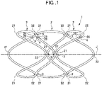
- FIG. 1 is a perspective view showing the stent 1 according to the first embodiment of the present invention.
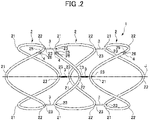
- FIG. 2 is an exploded view of the stent 1 according to the present embodiment.
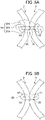
- FIG. 3 shows a joined state of adjacent polygonal annular portions 2.
- FIG. 4 shows a joined state of one end part 25 and the other end part 26 of a polygonal annular portion 2.
- the stent 1 of the present embodiment is formed of biodegradable fibers (linear members) and has a plurality of openings. As shown in FIG. 1 , the stent 1 is formed in a cylindrical shape extending in the axial direction J as a whole, and is deformable between a reduced diameter state (extended in the axial direction J) and an expanded diameter state (contracted in the axial direction J).
- the stent 1 is formed in a cylindrical shape having a plurality of openings by connecting a plurality of polygonal annular portions 2 side by side in the axial direction J.
- Each of the plurality of polygonal annular portions 2 is formed of a synthetic resin fiber and in an annular shape.
- the polygonal annular portion 2 has bent parts 21 and 22 formed by alternately bending toward one side and toward the other side in the axial direction J, in the middle of a circumferential direction.
- the bent parts 21 and 22 respectively constitute mountain parts and valley parts of the polygonal annular portion 2.
- the number of the mountain parts of the polygonal annular portion 2 is, for example, three.
- the bent part 21 is formed to be convex toward one side (the left side in FIGS. 1 and 2 ) in the axial direction J
- the bent part 22 is formed to be convex toward the other side (the right side in FIGS. 1 and 2 ) in the axial direction J.
- the polygonal annular portions 2 adjacent to each other in the axial direction are connected to each other in the axial direction J with a joining member 3.
- the adjacent polygonal annular portions 2 are connected with the joining member 3 at the bent parts 21 and 22, which are convex on the side where they approach each other in the axial direction.
- through holes 23 passing through in the axial direction J are respectively formed in the bent parts 21 and 22 of the biodegradable fibers (linear members) constituting the polygonal annular portions 2 adjacent to each other in the axial direction J.
- the through hole 23 is formed in the biodegradable fiber with, for example, a needle, a laser, or the like.
- the shape of the through hole 23 is, for example, circular or quadrangular.
- a joining member linear part 31 of a linear joining member 3 is inserted into the through hole 23, and processed end parts 32 formed at both ends in the direction in which the joining member linear part 31 extends, are processed by melting with heat. Thus, the processed end part 32 has a larger diameter than the through hole 23.
- the joining member 3 passes through the through holes 23 and extends in the axial direction J.
- the joining member 3 passes through the two through holes 23 of the biodegradable fibers constituting the adjacent polygonal annular portions 2.
- the biodegradable fiber (linear member) constituting each of the polygonal annular portions 2 is formed in an annular shape around the central axis extending in the axial direction J by joining the one end part 25 and the other end part 26.
- the one end part 25 and the other end part 26 of the biodegradable fiber constituting the polygonal annular portion 2 are cut at an angle to the direction in which the biodegradable fiber extends, and are joined by overlapping the oblique cut surfaces with each other.
- the one end part 25 and the other end part 26 of the biodegradable fiber constituting the polygonal annular portion 2 may not be cut at an angle to the direction in which the biodegradable fiber extends, but may be cut orthogonal to the direction in which the biodegradable fiber extends.
- the one end part 25 and the other end part 26 may be disposed so as to overlap each other in the axial direction J.
- through holes 27 passing through in the axial direction J are formed in the one end part 25 and the other end part 26 of the biodegradable fiber (linear member) constituting the polygonal annular portion 2.
- a joining member linear part 41 of a linear joining member 4 is inserted into the through holes 27, and processed end parts 42 formed at both ends in the direction in which the joining member linear part 41 extends are processed by melting with heat. Thereby, the processed end part 42 has a larger diameter than the through hole 27.
- the joining member 4 passes through the through holes 27 and extends in the axial direction J.
- the joining member 4 passes through the two through holes 23 of the biodegradable fibers constituting the adjacent polygonal annular portions 2.
- the materials of the linear member and the joining members 3 and 4 constituting the polygonal annular portion 2 are not limited, but, for example, in the present embodiment, a biodegradable resin is used.
- a biodegradable resin for example, polylactic acid (PLA) or polydioxanone (PDO) is used.
- PLA polylactic acid
- PDO polydioxanone
- the materials of the linear member constituting the polygonal annular portion 2 and the joining members 3 and 4 are not limited thereto, and for example, a non-biodegradable resin or a biodegradable metal such as magnesium may be used.
- the fiber diameter of the synthetic resin fiber constituting the stent 1 is, for example, 0.05 mm to 0.7 mm, preferably 0.4 mm to 0.6 mm.
- the hole diameter of the through hole 23 is preferably 0.2 mm to 0.3 mm.
- the size of the stent 1 is not limited, but, for example, the stent 1 has a diameter of 10 to 25 mm and a length of 30 to 250 mm in a state where the stent 1 is expanded in diameter.
- the following stent 1 is made.
- the stent 1 is made by using PDO fibers (fiber diameter: 0.4 mm to 0.6 mm) and connecting three polygonal annular portions 2 in the axial direction J.
- a round through hole 23 is formed with a needle having a diameter of 0.2 mm in each of the bent parts 21 and 22 of the PDO fiber (fiber diameter: 0.4 mm to 0.6 mm).
- the measured diameter of the through hole 23 is 0.197 mm.
- Each of the polygonal annular portions 2 is joined to each other by using a joining member 3 made of a PLA fiber (fiber diameter: 0.2 mm) in the through holes 23 formed in the bent parts 21 and 22. After the joining member 3 made of the PLA fiber (fiber diameter: 0.2 mm) is inserted into the through hole 23, both end parts of the joining member 3 are processed by melting with heat to prevent the joining member 3 from coming out of the through hole 23.
- Forming the through hole 23 is not limited to forming the through hole 23 with a needle, and a laser may be used to form the through hole 23.
- a PDO fiber fiber diameter: 0.56 mm
- the through hole 23 is formed in the bent parts 21 and 22 made of the PDO fiber (fiber diameter: 0.56 mm) with a laser.
- the average of the measured diameters of the through holes 23 (the average of six locations) is 0.186 mm.
- FIG. 5A shows a joining member 3A of a first modification.
- FIG. 5B shows a joining member 3B of a second modification.
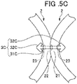
- FIG. 5C shows a joining member 3C of a third modification.
- the joining members 3A, 3B, and 3C of the modifications the case in which the polygonal annular portions 2 are connected to each other in the axial direction J will be described, but the same applies to the case in which the one end part 25 and the other end part 26 of the polygonal annular portion 2 are connected to each other in the axial direction J in the above-described embodiment.
- the joining member 3A of the first modification is configured by forming knots 32A and 32A at both end parts of a linear joining member main body 31A.
- the joining member 3B of the second modification is formed in a ring shape in a state of passing through the through hole 23.
- the joining member 3C of the third modification is configured in the following manner: Folded parts 32C and 32C are formed at both end parts of a linear joining member main body 31C. The folded parts 32C and 32C are folded and the joining member main body 31C is inserted into the through hole 23 without processing the both end parts of the joining member main body 31C.
- the folded part 32C is spread so as to catch the biodegradable fiber (linear member) constituting the polygonal annular portion 2.
- the joining member 3A of the first modification, the joining member 3B of the second modification, and the joining member 3C of the third modification the same effects as those of the above-described embodiment can be achieved.
- the present invention is not limited to the above-described embodiment and can be as appropriate modified.
- biodegradable fibers are used as the linear members of the stent, but the present invention is not limited thereto. That is, non-biodegradable synthetic resin fibers may be used to construct the stent.
- the stent may be formed of a biodegradable metallic material such as magnesium as the linear member of the stent.
- the stent 1 formed by connecting the plurality of polygonal annular portions 2 side by side in the axial direction J has been described.
- the phrase 'the stent is formed by connecting a plurality of polygonal annular portions side by side in an axial direction' means that the stent is formed to have a shape in which a plurality of polygonal annular portions are arranged in the axial direction.
- a plurality of polygonal annular portions may be separately made and formed side by side in the axial direction, and may be connected to each other with joining members extending in the axial direction at locations where connection is required.
- a plurality of polygonal annular portions may be formed side by side by knitting one or more linear members in a spiral shape, and connected to each other with joining members extending in the axial direction at locations where connection is required.
- the number of the linear members is not limited.
- the stent 1 in which three polygonal annular portions 2 are connected side by side in the axial direction J has been described, but the present invention is not limited thereto.
- the stent 1 may be formed by connecting four or more polygonal annular portions 2 side by side in the axial direction J.
- the number of corners of the polygonal annular portion 2 is not limited.
- a stent 1A of a second embodiment will be described.
- the description of the first embodiment can be referred to for portions not described in the second embodiment.
- the stent 1A of the present embodiment is formed of biodegradable fibers (linear members) and has a plurality of openings.
- the stent 1A is formed in a cylindrical shape extending in an axial direction J1 as a whole, and is deformable between a reduced diameter state (extended in the axial direction J1) and an expanded diameter state (contracted in the axial direction J1).
- the stent 1A is formed in a cylindrical shape having a plurality of openings by connecting a plurality of polygonal annular portions 6 side by side in the axial direction J1.
- Each of the plurality of polygonal annular portions 6 is formed of a synthetic resin fiber and in an annular shape.
- the polygonal annular portion 6 has bent parts 61 and 62 formed by alternately bending one side and the other side in the axial direction J1 in the middle of a circumferential direction.
- the bent parts 61 and 62 respectively constitute mountain and valley parts of the polygonal annular portion 6.
- the bent part 61 is formed to be convex toward one side (the left side in FIG. 6 ) in the axial direction J1
- the bent part 62 is formed to be convex toward the other side (the right side in FIG. 6 ) in the axial direction J1.
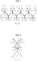
- the polygonal annular portions 6 adjacent to each other in the axial direction are connected to each other in the axial direction J1 with a plurality of linear joining members 7 (joining members) at bent parts 61 and 62 which are convex toward each other in the axial direction.
- Each of the plurality of linear joining members 7 is formed of one linear member and joins two through holes 63 at each of a plurality of locations along the axial direction of the stent 1A.
- Each of the linear joining members 7 formed of one linear member linearly extends in the axial direction of the stent 1A in a zigzag shape in which the circumferential position of the stent 1A is alternately shifted to one side and the other side.
- the plurality of linear joining members 7 are provided apart from each other in the circumferential direction of the stent 1A.
- the through holes 63 passing through in the axial direction J1 are respectively formed in the biodegradable fibers constituting the polygonal annular portions 6 adjacent to each other in the axial direction J1.
- the through hole 63 is formed in the biodegradable fiber with, for example, a needle, a laser, or the like.
- the shape of the through hole 63 is, for example, circular or quadrangular.
- the linear joining member 7 is inserted into the through hole 63.
- each of the plurality of linear joining members 7 joins the biodegradable fibers constituting the polygonal annular portions 6 adjacent to each other in the axial direction, at a plurality of intermediate joining parts 71 disposed on the inner side of both axial ends of the stent 1A, and joins the polygonal annular portions 6 adjacent to each other in the axial direction, at end side joining parts 72 disposed on both axial end sides of the stent 1A.
- the linear joining member 7 passes through the two through holes 63 of the biodegradable fibers constituting the adjacent polygonal annular portions 6 and crosses, thereby joining the biodegradable fibers constituting the polygonal annular portions 6 adjacent to each other in the axial direction.
- the linear joining member 7 extends in the axial direction at the part of the intermediate joining part 71 in which the linear joining member 7 passes through the two through holes 63.
- the linear joining member 7 passes through the two through holes 63 of the biodegradable fibers constituting the adjacent polygonal annular portions 6, and joins the biodegradable fibers constituting the polygonal annular portions 6 adjacent to each other in the axial direction by fixing a tube 73 having an outer diameter larger than that of the through hole 63 to an end part of the linear joining member 7 with an adhesive.
- the linear joining member 7 extends in the axial direction at the part of the end side joining part 72 in which the linear joining member 7 passes through the two through holes 63.
- the joining state with the linear joining member 7 at the end side joining part 72 is not limited thereto.
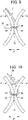
- a linear joining member 7A passes through the two through holes 63, and the end part of the linear joining member 7A may be crossed and tied to form a figure 8 , thereby joining the biodegradable fibers constituting the polygonal annular portions 6 adjacent to each other in the axial direction.
- the same effects as those of the stent 1 of the first embodiment can be achieved.
- the biodegradable fibers constituting the polygonal annular portions 6 adjacent to each other in the axial direction J1 are joined to each other by the linear joining member 7 passing through the two through holes 63, whereby the radial bulkiness of the stent 1 can be reduced. Therefore, for example, when the stent 1 is placed in a gastrointestinal tract with a stent delivery system, it is possible to improve the storability in the stent delivery system.
- one linear joining member 7 joins the biodegradable fibers constituting the polygonal annular portions 6 adjacent to each other in the axial direction of the stent 1 by passing through the two through holes 63 and crossing.
- the two through holes 63 are joined at each of a plurality of locations along the axial direction of the stent 1.
- the two through holes 23 are joined to each other with the joining member 3 having a short length and end parts processed by melting with heat.
- the joining member 3 having a short length and end parts processed by melting with heat.
- one linear joining member 7 joins the two through holes 63 at each of a plurality of locations along the axial direction of the stent 1, the tensile strength when the biodegradable fiber constituting the polygonal annular portion 6 is pulled can be improved.
- the present invention will be specifically described with reference to an example, but the present invention is not limited to the following example.
- the stents of the following example and comparative example were each stored in a stent delivery system.
- the stents of both the example and the comparative example were each formed by connecting three polygonal annular portions 2 in an axial direction J.
- the polygonal annular portion 2 was formed of a PDO fiber (fiber diameter: 0.40 mm to 0.499 mm), and had a number of mountains of three.
- the stent diameter was 18 mm.
- adjacent polygonal annular portions 2 were connected to each other with a joining member 3.
- bent parts of adjacent polygonal annular portions 2 facing each other were inserted into a tube and fixed with an adhesive to connect the adjacent polygonal annular portions 2.
- the stent delivery system includes a cylindrical outer sheath member (outer cylinder) (not shown) inserted into the gastrointestinal tract, and a pusher member (not shown).
- a stent can be stored inside the outer sheath member.
- the stent is disposed inside the outer sheath member in a reduced diameter state (extended state in an axially direction). In this state, the stent is pushed out from the distal end side of the outer sheath member by the pusher member disposed on the proximal end side inside the outer sheath member.
- the stent is pushed out from the distal end side of the outer sheath member, expanded in diameter inside the gastrointestinal tract, and placed inside the gastrointestinal tract.
Landscapes
- Health & Medical Sciences (AREA)
- Engineering & Computer Science (AREA)
- Biomedical Technology (AREA)
- Cardiology (AREA)
- Oral & Maxillofacial Surgery (AREA)
- Transplantation (AREA)
- Heart & Thoracic Surgery (AREA)
- Vascular Medicine (AREA)
- Life Sciences & Earth Sciences (AREA)
- Animal Behavior & Ethology (AREA)
- General Health & Medical Sciences (AREA)
- Public Health (AREA)
- Veterinary Medicine (AREA)
- Media Introduction/Drainage Providing Device (AREA)
Applications Claiming Priority (2)
| Application Number | Priority Date | Filing Date | Title |
|---|---|---|---|
| JP2020043037 | 2020-03-12 | ||
| PCT/JP2021/009327 WO2021182475A1 (fr) | 2020-03-12 | 2021-03-09 | Stent |
Publications (3)
| Publication Number | Publication Date |
|---|---|
| EP4119105A1 true EP4119105A1 (fr) | 2023-01-18 |
| EP4119105A4 EP4119105A4 (fr) | 2024-03-20 |
| EP4119105B1 EP4119105B1 (fr) | 2025-05-07 |
Family
ID=77672387
Family Applications (1)
| Application Number | Title | Priority Date | Filing Date |
|---|---|---|---|
| EP21767297.1A Active EP4119105B1 (fr) | 2020-03-12 | 2021-03-09 | Stent |
Country Status (5)
| Country | Link |
|---|---|
| US (1) | US20230138256A1 (fr) |
| EP (1) | EP4119105B1 (fr) |
| JP (1) | JP7582293B2 (fr) |
| CN (1) | CN115209843A (fr) |
| WO (1) | WO2021182475A1 (fr) |
Family Cites Families (14)
| Publication number | Priority date | Publication date | Assignee | Title |
|---|---|---|---|---|
| WO1997033532A2 (fr) * | 1996-03-13 | 1997-09-18 | Medtronic, Inc. | Prothese endoluminale et therapies pour des organes du corps humain a plusieurs lumieres et rameaux |
| US6340367B1 (en) * | 1997-08-01 | 2002-01-22 | Boston Scientific Scimed, Inc. | Radiopaque markers and methods of using the same |
| GB2347861B (en) * | 1999-03-13 | 2003-11-26 | Biointeractions Ltd | Biocompatible endoprostheses |
| US6964676B1 (en) * | 2000-04-14 | 2005-11-15 | Scimed Life Systems, Inc. | Stent securement system |
| DE10103000B4 (de) * | 2001-01-24 | 2007-08-30 | Qualimed Innovative Medizinprodukte Gmbh | Radial reexpandierbare Gefäßstütze |
| ATE487445T1 (de) * | 2005-07-25 | 2010-11-15 | Invatec Spa | Endoluminale prothese mit bioresorbierbaren abschnitten |
| JP5384359B2 (ja) | 2007-10-16 | 2014-01-08 | 株式会社 京都医療設計 | 脈管ステント用の管状体形成エレメント及び脈管ステント |
| KR20120045608A (ko) * | 2010-10-29 | 2012-05-09 | 메디소스플러스(주) | 스텐트와이어 및 스텐트와이어 제조방법 |
| EP3424469A1 (fr) * | 2012-02-22 | 2019-01-09 | Syntheon TAVR, LLC | Endoprothèse à commande active, greffe d'endoprothèse et valvule cardiaque |
| ES2641998T3 (es) * | 2012-06-07 | 2017-11-14 | Boston Scientific Scimed, Inc. | Aparato de sustitución de una válvula cardíaca nativa |
| US20140172074A1 (en) * | 2012-12-13 | 2014-06-19 | 480 Biomedical, Inc. | Stent with reinforced joints |
| WO2017200956A1 (fr) * | 2016-05-16 | 2017-11-23 | Elixir Medical Corporation | Libération de stent |
| CN108670510B (zh) * | 2018-05-22 | 2020-03-27 | 淮阴工学院 | 一种柔顺性优异的颅内血管支架 |
| US12251326B2 (en) * | 2019-03-28 | 2025-03-18 | Jms Co., Ltd. | Synthetic resin stent |
-
2021
- 2021-03-09 WO PCT/JP2021/009327 patent/WO2021182475A1/fr not_active Ceased
- 2021-03-09 EP EP21767297.1A patent/EP4119105B1/fr active Active
- 2021-03-09 CN CN202180017447.8A patent/CN115209843A/zh active Pending
- 2021-03-09 JP JP2022507224A patent/JP7582293B2/ja active Active
- 2021-03-09 US US17/910,643 patent/US20230138256A1/en active Pending
Also Published As
| Publication number | Publication date |
|---|---|
| US20230138256A1 (en) | 2023-05-04 |
| CN115209843A (zh) | 2022-10-18 |
| WO2021182475A1 (fr) | 2021-09-16 |
| JP7582293B2 (ja) | 2024-11-13 |
| EP4119105A4 (fr) | 2024-03-20 |
| EP4119105B1 (fr) | 2025-05-07 |
| JPWO2021182475A1 (fr) | 2021-09-16 |
Similar Documents
| Publication | Publication Date | Title |
|---|---|---|
| EP2255750B1 (fr) | Stent hélicoïdal à flexibilité et capacité d'expansion améliorées | |
| JP7097166B2 (ja) | 柔軟性ステント | |
| EP2301487A2 (fr) | Implant et système de distribution doté de plusieurs verrouillages de marqueur | |
| US9737319B2 (en) | Anti-retropulsion systems and methods | |
| JP7760807B2 (ja) | 胆管ステント | |
| JP7782127B2 (ja) | ステント留置システム | |
| CN113274166B (zh) | 覆膜支架及输送系统 | |
| EP4119105A1 (fr) | Stent | |
| EP4659715A1 (fr) | Procédé de production d'endoprothèse équipée d'un fil, endoprothèse équipée d'un fil et dispositif de pose d'endoprothèse | |
| EP3949915B1 (fr) | Endoprothèse en résine synthétique | |
| JP2024139728A (ja) | アウターシース付きステント、ステントデリバリー装置及びアウターシース付きステント製造方法 | |
| JP7039957B2 (ja) | ステント | |
| JP2019063522A (ja) | ステント | |
| JP6729552B2 (ja) | 合成樹脂ステント | |
| CN114305817B (zh) | 一种抗塌陷的血管支架 | |
| JP2019118810A (ja) | 内腔拡張用3重構造ステント及びその製造方法 | |
| WO2022191209A1 (fr) | Cathéter et système d'administration | |
| JP2024110935A (ja) | ストリング付きステントの製造方法、ストリング付きステント及びステントデリバリー装置 | |
| WO2023163122A1 (fr) | Cathéter et système de mise en place | |
| JP2024136826A (ja) | カテーテル | |
| JP2025064119A (ja) | 管状留置具付き留置装置 | |
| JP2024139727A (ja) | アウターシース付きステント、ステントデリバリー装置及びアウターシース付きステント製造方法 | |
| JP2023078582A (ja) | ステントデリバリーシステム | |
| JP2024018394A (ja) | ステントグラフト、及び、グラフト留置装置 | |
| WO2020079825A1 (fr) | Cathéter |
Legal Events
| Date | Code | Title | Description |
|---|---|---|---|
| STAA | Information on the status of an ep patent application or granted ep patent |
Free format text: STATUS: THE INTERNATIONAL PUBLICATION HAS BEEN MADE |
|
| PUAI | Public reference made under article 153(3) epc to a published international application that has entered the european phase |
Free format text: ORIGINAL CODE: 0009012 |
|
| STAA | Information on the status of an ep patent application or granted ep patent |
Free format text: STATUS: REQUEST FOR EXAMINATION WAS MADE |
|
| 17P | Request for examination filed |
Effective date: 20220907 |
|
| AK | Designated contracting states |
Kind code of ref document: A1 Designated state(s): AL AT BE BG CH CY CZ DE DK EE ES FI FR GB GR HR HU IE IS IT LI LT LU LV MC MK MT NL NO PL PT RO RS SE SI SK SM TR |
|
| DAV | Request for validation of the european patent (deleted) | ||
| DAX | Request for extension of the european patent (deleted) | ||
| A4 | Supplementary search report drawn up and despatched |
Effective date: 20240221 |
|
| RIC1 | Information provided on ipc code assigned before grant |
Ipc: A61F 2/90 20130101ALI20240215BHEP Ipc: A61F 2/89 20130101AFI20240215BHEP |
|
| GRAP | Despatch of communication of intention to grant a patent |
Free format text: ORIGINAL CODE: EPIDOSNIGR1 |
|
| STAA | Information on the status of an ep patent application or granted ep patent |
Free format text: STATUS: GRANT OF PATENT IS INTENDED |
|
| INTG | Intention to grant announced |
Effective date: 20241210 |
|
| GRAS | Grant fee paid |
Free format text: ORIGINAL CODE: EPIDOSNIGR3 |
|
| GRAA | (expected) grant |
Free format text: ORIGINAL CODE: 0009210 |
|
| STAA | Information on the status of an ep patent application or granted ep patent |
Free format text: STATUS: THE PATENT HAS BEEN GRANTED |
|
| AK | Designated contracting states |
Kind code of ref document: B1 Designated state(s): AL AT BE BG CH CY CZ DE DK EE ES FI FR GB GR HR HU IE IS IT LI LT LU LV MC MK MT NL NO PL PT RO RS SE SI SK SM TR |
|
| REG | Reference to a national code |
Ref country code: GB Ref legal event code: FG4D |
|
| REG | Reference to a national code |
Ref country code: CH Ref legal event code: EP |
|
| REG | Reference to a national code |
Ref country code: DE Ref legal event code: R096 Ref document number: 602021030487 Country of ref document: DE |
|
| REG | Reference to a national code |
Ref country code: IE Ref legal event code: FG4D |
|
| REG | Reference to a national code |
Ref country code: NL Ref legal event code: MP Effective date: 20250507 |
|
| PG25 | Lapsed in a contracting state [announced via postgrant information from national office to epo] |
Ref country code: PT Free format text: LAPSE BECAUSE OF FAILURE TO SUBMIT A TRANSLATION OF THE DESCRIPTION OR TO PAY THE FEE WITHIN THE PRESCRIBED TIME-LIMIT Effective date: 20250908 Ref country code: ES Free format text: LAPSE BECAUSE OF FAILURE TO SUBMIT A TRANSLATION OF THE DESCRIPTION OR TO PAY THE FEE WITHIN THE PRESCRIBED TIME-LIMIT Effective date: 20250507 Ref country code: FI Free format text: LAPSE BECAUSE OF FAILURE TO SUBMIT A TRANSLATION OF THE DESCRIPTION OR TO PAY THE FEE WITHIN THE PRESCRIBED TIME-LIMIT Effective date: 20250507 |
|
| REG | Reference to a national code |
Ref country code: LT Ref legal event code: MG9D |
|
| PG25 | Lapsed in a contracting state [announced via postgrant information from national office to epo] |
Ref country code: NO Free format text: LAPSE BECAUSE OF FAILURE TO SUBMIT A TRANSLATION OF THE DESCRIPTION OR TO PAY THE FEE WITHIN THE PRESCRIBED TIME-LIMIT Effective date: 20250807 Ref country code: GR Free format text: LAPSE BECAUSE OF FAILURE TO SUBMIT A TRANSLATION OF THE DESCRIPTION OR TO PAY THE FEE WITHIN THE PRESCRIBED TIME-LIMIT Effective date: 20250808 |
|
| PG25 | Lapsed in a contracting state [announced via postgrant information from national office to epo] |
Ref country code: NL Free format text: LAPSE BECAUSE OF FAILURE TO SUBMIT A TRANSLATION OF THE DESCRIPTION OR TO PAY THE FEE WITHIN THE PRESCRIBED TIME-LIMIT Effective date: 20250507 Ref country code: PL Free format text: LAPSE BECAUSE OF FAILURE TO SUBMIT A TRANSLATION OF THE DESCRIPTION OR TO PAY THE FEE WITHIN THE PRESCRIBED TIME-LIMIT Effective date: 20250507 |
|
| REG | Reference to a national code |
Ref country code: AT Ref legal event code: MK05 Ref document number: 1791651 Country of ref document: AT Kind code of ref document: T Effective date: 20250507 |
|
| PG25 | Lapsed in a contracting state [announced via postgrant information from national office to epo] |
Ref country code: BG Free format text: LAPSE BECAUSE OF FAILURE TO SUBMIT A TRANSLATION OF THE DESCRIPTION OR TO PAY THE FEE WITHIN THE PRESCRIBED TIME-LIMIT Effective date: 20250507 |
|
| PG25 | Lapsed in a contracting state [announced via postgrant information from national office to epo] |
Ref country code: HR Free format text: LAPSE BECAUSE OF FAILURE TO SUBMIT A TRANSLATION OF THE DESCRIPTION OR TO PAY THE FEE WITHIN THE PRESCRIBED TIME-LIMIT Effective date: 20250507 |
|
| PG25 | Lapsed in a contracting state [announced via postgrant information from national office to epo] |
Ref country code: AT Free format text: LAPSE BECAUSE OF FAILURE TO SUBMIT A TRANSLATION OF THE DESCRIPTION OR TO PAY THE FEE WITHIN THE PRESCRIBED TIME-LIMIT Effective date: 20250507 |
|
| PG25 | Lapsed in a contracting state [announced via postgrant information from national office to epo] |
Ref country code: RS Free format text: LAPSE BECAUSE OF FAILURE TO SUBMIT A TRANSLATION OF THE DESCRIPTION OR TO PAY THE FEE WITHIN THE PRESCRIBED TIME-LIMIT Effective date: 20250807 |
|
| PG25 | Lapsed in a contracting state [announced via postgrant information from national office to epo] |
Ref country code: IS Free format text: LAPSE BECAUSE OF FAILURE TO SUBMIT A TRANSLATION OF THE DESCRIPTION OR TO PAY THE FEE WITHIN THE PRESCRIBED TIME-LIMIT Effective date: 20250907 |
|
| PG25 | Lapsed in a contracting state [announced via postgrant information from national office to epo] |
Ref country code: LV Free format text: LAPSE BECAUSE OF FAILURE TO SUBMIT A TRANSLATION OF THE DESCRIPTION OR TO PAY THE FEE WITHIN THE PRESCRIBED TIME-LIMIT Effective date: 20250507 |
|
| PG25 | Lapsed in a contracting state [announced via postgrant information from national office to epo] |
Ref country code: DK Free format text: LAPSE BECAUSE OF FAILURE TO SUBMIT A TRANSLATION OF THE DESCRIPTION OR TO PAY THE FEE WITHIN THE PRESCRIBED TIME-LIMIT Effective date: 20250507 Ref country code: SM Free format text: LAPSE BECAUSE OF FAILURE TO SUBMIT A TRANSLATION OF THE DESCRIPTION OR TO PAY THE FEE WITHIN THE PRESCRIBED TIME-LIMIT Effective date: 20250507 |
|
| PG25 | Lapsed in a contracting state [announced via postgrant information from national office to epo] |
Ref country code: CZ Free format text: LAPSE BECAUSE OF FAILURE TO SUBMIT A TRANSLATION OF THE DESCRIPTION OR TO PAY THE FEE WITHIN THE PRESCRIBED TIME-LIMIT Effective date: 20250507 |
|
| PG25 | Lapsed in a contracting state [announced via postgrant information from national office to epo] |
Ref country code: EE Free format text: LAPSE BECAUSE OF FAILURE TO SUBMIT A TRANSLATION OF THE DESCRIPTION OR TO PAY THE FEE WITHIN THE PRESCRIBED TIME-LIMIT Effective date: 20250507 |
|
| PG25 | Lapsed in a contracting state [announced via postgrant information from national office to epo] |
Ref country code: SK Free format text: LAPSE BECAUSE OF FAILURE TO SUBMIT A TRANSLATION OF THE DESCRIPTION OR TO PAY THE FEE WITHIN THE PRESCRIBED TIME-LIMIT Effective date: 20250507 |
|
| PG25 | Lapsed in a contracting state [announced via postgrant information from national office to epo] |
Ref country code: IT Free format text: LAPSE BECAUSE OF FAILURE TO SUBMIT A TRANSLATION OF THE DESCRIPTION OR TO PAY THE FEE WITHIN THE PRESCRIBED TIME-LIMIT Effective date: 20250507 |
|
| REG | Reference to a national code |
Ref country code: DE Ref legal event code: R097 Ref document number: 602021030487 Country of ref document: DE |
|
| PLBE | No opposition filed within time limit |
Free format text: ORIGINAL CODE: 0009261 |
|
| STAA | Information on the status of an ep patent application or granted ep patent |
Free format text: STATUS: NO OPPOSITION FILED WITHIN TIME LIMIT |
|
| REG | Reference to a national code |
Ref country code: CH Ref legal event code: L10 Free format text: ST27 STATUS EVENT CODE: U-0-0-L10-L00 (AS PROVIDED BY THE NATIONAL OFFICE) Effective date: 20260318 |
|
| PGFP | Annual fee paid to national office [announced via postgrant information from national office to epo] |
Ref country code: DE Payment date: 20260319 Year of fee payment: 6 |
|
| 26N | No opposition filed |
Effective date: 20260210 |