EP4119372A1 - Siège de véhicule à moteur - Google Patents
Siège de véhicule à moteur Download PDFInfo
- Publication number
- EP4119372A1 EP4119372A1 EP22173574.9A EP22173574A EP4119372A1 EP 4119372 A1 EP4119372 A1 EP 4119372A1 EP 22173574 A EP22173574 A EP 22173574A EP 4119372 A1 EP4119372 A1 EP 4119372A1
- Authority
- EP
- European Patent Office
- Prior art keywords
- seat
- backrest portion
- motor vehicle
- dividing wall
- frame portion
- Prior art date
- Legal status (The legal status is an assumption and is not a legal conclusion. Google has not performed a legal analysis and makes no representation as to the accuracy of the status listed.)
- Pending
Links
Images

Classifications
-
- B—PERFORMING OPERATIONS; TRANSPORTING
- B60—VEHICLES IN GENERAL
- B60N—SEATS SPECIALLY ADAPTED FOR VEHICLES; VEHICLE PASSENGER ACCOMMODATION NOT OTHERWISE PROVIDED FOR
- B60N2/00—Seats specially adapted for vehicles; Arrangement or mounting of seats in vehicles
- B60N2/02—Seats specially adapted for vehicles; Arrangement or mounting of seats in vehicles the seat or part thereof being movable, e.g. adjustable
- B60N2/22—Seats specially adapted for vehicles; Arrangement or mounting of seats in vehicles the seat or part thereof being movable, e.g. adjustable the back-rest being adjustable
-
- B—PERFORMING OPERATIONS; TRANSPORTING
- B60—VEHICLES IN GENERAL
- B60N—SEATS SPECIALLY ADAPTED FOR VEHICLES; VEHICLE PASSENGER ACCOMMODATION NOT OTHERWISE PROVIDED FOR
- B60N2/00—Seats specially adapted for vehicles; Arrangement or mounting of seats in vehicles
- B60N2/24—Seats specially adapted for vehicles; Arrangement or mounting of seats in vehicles for particular purposes or particular vehicles
- B60N2/30—Non-dismountable or dismountable seats storable in a non-use position, e.g. foldable spare seats
- B60N2/3002—Non-dismountable or dismountable seats storable in a non-use position, e.g. foldable spare seats back-rest movements
- B60N2/3004—Non-dismountable or dismountable seats storable in a non-use position, e.g. foldable spare seats back-rest movements by rotation only
- B60N2/3009—Non-dismountable or dismountable seats storable in a non-use position, e.g. foldable spare seats back-rest movements by rotation only about transversal axis
- B60N2/3013—Non-dismountable or dismountable seats storable in a non-use position, e.g. foldable spare seats back-rest movements by rotation only about transversal axis the back-rest being hinged on the vehicle frame
- B60N2/3015—Non-dismountable or dismountable seats storable in a non-use position, e.g. foldable spare seats back-rest movements by rotation only about transversal axis the back-rest being hinged on the vehicle frame the axis being located at the top of the back-rest
-
- B—PERFORMING OPERATIONS; TRANSPORTING
- B60—VEHICLES IN GENERAL
- B60J—WINDOWS, WINDSCREENS, NON-FIXED ROOFS, DOORS, OR SIMILAR DEVICES FOR VEHICLES; REMOVABLE EXTERNAL PROTECTIVE COVERINGS SPECIALLY ADAPTED FOR VEHICLES
- B60J7/00—Non-fixed roofs; Roofs with movable panels, e.g. rotary sunroofs
- B60J7/22—Wind deflectors for open roofs
- B60J7/223—Wind deflectors for open roofs specially adapted for convertible cars
-
- B—PERFORMING OPERATIONS; TRANSPORTING
- B60—VEHICLES IN GENERAL
- B60N—SEATS SPECIALLY ADAPTED FOR VEHICLES; VEHICLE PASSENGER ACCOMMODATION NOT OTHERWISE PROVIDED FOR
- B60N2/00—Seats specially adapted for vehicles; Arrangement or mounting of seats in vehicles
- B60N2/24—Seats specially adapted for vehicles; Arrangement or mounting of seats in vehicles for particular purposes or particular vehicles
- B60N2/32—Seats specially adapted for vehicles; Arrangement or mounting of seats in vehicles for particular purposes or particular vehicles convertible for other use
-
- B—PERFORMING OPERATIONS; TRANSPORTING
- B60—VEHICLES IN GENERAL
- B60N—SEATS SPECIALLY ADAPTED FOR VEHICLES; VEHICLE PASSENGER ACCOMMODATION NOT OTHERWISE PROVIDED FOR
- B60N2/00—Seats specially adapted for vehicles; Arrangement or mounting of seats in vehicles
- B60N2/80—Head-rests
- B60N2/803—Head-rests fixed
-
- B—PERFORMING OPERATIONS; TRANSPORTING
- B60—VEHICLES IN GENERAL
- B60N—SEATS SPECIALLY ADAPTED FOR VEHICLES; VEHICLE PASSENGER ACCOMMODATION NOT OTHERWISE PROVIDED FOR
- B60N2/00—Seats specially adapted for vehicles; Arrangement or mounting of seats in vehicles
- B60N2/24—Seats specially adapted for vehicles; Arrangement or mounting of seats in vehicles for particular purposes or particular vehicles
- B60N2/32—Seats specially adapted for vehicles; Arrangement or mounting of seats in vehicles for particular purposes or particular vehicles convertible for other use
- B60N2/36—Seats specially adapted for vehicles; Arrangement or mounting of seats in vehicles for particular purposes or particular vehicles convertible for other use into a loading platform
- B60N2002/363—Seats specially adapted for vehicles; Arrangement or mounting of seats in vehicles for particular purposes or particular vehicles convertible for other use into a loading platform characterised by provisions for enhancing the cargo floor surface, e.g. elements closing gaps or enlarging the back-rest surface
Definitions
- the invention relates to a seat for a motor vehicle, in particular a convertible one.
- the aforesaid undesired phenomenon is further worsened when the motor vehicle travels at relatively high speeds, for example along suburban paths or on a motorway.
- the wind deflector is removable for those cases in which its use is not necessary; therefore, the vehicle is typically provided with a storage compartment designed to easily accommodate the wind deflector, which was removed and - if necessary - folded onto itself, in case of a pliable wind deflector.
- the free spaces of the motor vehicle need to be redistributed, assigning at least part of the space needed to accommodate the wind deflector to other uses or, simply, to an increase in the passengers' comfort in the passenger compartment.
- the object of the invention is to fulfil at least one of the needs discussed above, preferably in a simple and effective fashion.
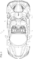
- reference number 1 is used to indicate, as a whole, a motor vehicle. More precisely, the motor vehicle 1 is a convertible motor vehicle.
- the motor vehicle 1 comprises a passenger compartment 2 and a roof 3, which can be configured between an open configuration, in which the passenger compartment 2 is open to the outside, and a closed configuration to close the passenger compartment 2, in particular when all the other openings of the motor vehicle 1 are closed (for instance, windows, openings of the doors or of the trunk).
- the passenger compartment 2 could always be open to the outside; in other words, the motor vehicle 1 could lack the roof 3.
- the motor vehicle 1 comprises a seat 4, in particular a rear seat, more in particular a bench seat.
- the seat 4 comprises a plurality of bodies or portions 5, 6, 7, the portion 6 defining at least a backrest portion, specifically the entire backrest.
- the portions 5 and 7 may, for example, be fixed; more in particular, the portion 5 defines a headrest.
- the portion 7 extends along the forward moving direction of the motor vehicle 1, namely along a horizontal direction, thus defining a base of the seat 4 suitable for supporting the legs of a passenger seating on the seat 4.
- the seat 4 comprises a mechanism 8 configured to couple the portion 6 to the portion 5 in a movable manner between a first and a second position.
- the portion 6 In the first position, shown in figure 2 , the portion 6 is arranged between the portions 5, 7 and is transversal to the portion 7, more precisely approximately orthogonal. In other words, the portion 6 extends in a substantially vertical manner in the first position. In this position, the seat 4 is suitable for supporting the passenger seating with the lower limbs resting against the portion 7 and the back resting against the portion 6 in the area of a surface 9 of the portion 6 itself.
- the portion 6 In the second position, the portion 6 extends along the horizontal direction above the portion 7. In other words, the portion 6 has a surface 10 opposite the surface 9 and facing the portion 7.
- the portion 6 becomes a wind deflector, at least when the roof 3 is in the open configuration. Namely, the portion 6 deflects an air flow directed towards the passenger compartment 2 towards the outside. More precisely, the air flow starts from a rear area of the motor vehicle 1 towards the passenger compartment 2. Here, the air flow meets the portion 6 in the second position brushing the surface 9, which is designed to support the back of the passenger in the first position.
- the portion 6, in the second position is tilted upwards relative to the horizontal direction, more in particular at an acute angle.
- an end 11 of the portion 6, more distant from the portion 5 reaches a height equal to or greater than the higher end 12 of the portion 5.
- the mechanism 8 consists of a hinge, so that the portion 6 is hinged to the first body 5 in a rotary manner in order to rotate around an axis H between the first and the second position.
- the axis H is horizontal and orthogonal to the forward moving direction of the motor vehicle 1.
- the mechanism 8 is manually operated.
- the mechanism 8 could also be electrically operated.
- the seat 4 comprises a frame portion 14. In the first position, the portion 6 is arranged between the end 11 and an end 15 of the frame portion 14.
- the frame portion 14 extends behind the seat 4 and, hence, behind the portion 6, both in the first and in the second position. Namely, the frame portion 14 extends on the opposite side of the portion 7 relative to the portion 6 in the first position.
- the seat 4 comprises a locking device 16, which is configured to fix the portion 6 to the frame portion 14 with the portion 6 in the first position.
- the locking device 16 can be closed in a snapping manner and be released by hand, for instance through a lever or a button or through a key.
- the locking device 16 can be closed by hand, as well. Possibly, the closing and/or the opening of the locking device 16 can be electrically operated.
- the seat 4 further comprises a dividing wall 17 coupled to at least one of the portion 5 and the frame portion 14 in a movable manner between a separation position and a communication position.
- the dividing wall 17 is arranged between the portion 5 and the frame portion 14. More in detail, the dividing wall 17 is arranged behind the portion 6 in the first position. In this position, the dividing wall 17 separates a space ahead or in front of the seat 4 from a space at the back of the seat 4, for example defined by a trunk of the motor vehicle 1. In particular, the dividing wall 17 extends in a substantially vertical manner from the point in which it rests against the portion 5 up to the point in which it is coupled to the frame portion 14. The latter defines at least one wall of the trunk.
- the dividing wall 17 frees a space between the portion 5 and the frame portion 14, such as to allow objects to be moved from the front of the seat 4 to the back thereof, at least when the portion 6 is in the second position.
- the dividing wall 17 is coupled to the frame portion 14, in particular is hinged to the latter in a rotary manner around a horizontal axis H1 orthogonal to the forward moving direction of the motor vehicle 1, and rests against the portion 5 in the separation position.
- the dividing wall 17 in the communication position, can be arranged on the portion 7.
- the dividing wall 17 faces the surface 10, when the portion 6 is in the second position.
- the dividing plate 17 is arranged between the portions 6, 7.
- the dividing wall 17 could rest on the portion 14.
- the dividing wall 17 could be rotated in a clockwise or counterclockwise direction.
- the dividing wall 17, in the separation position faces the surface 10 with the portion 6 in the first position.
- the seat 4 is multiuse, in that it can be used both as a seat and as a wind deflector; in this way, no removable wind deflector is needed and no storage compartment is needed to accommodate the wind deflector when it is not used. This corresponds to significant reduction in the space taken up in the motor vehicle 1.
- the use of the seat 4 as wind deflector is extremely simple. Users only have to handle the portion 6, for example releasing the locking device 16 and moving the portion 6 to the second position. Here, users can fix the second position of the portion 6 to a component of the motor vehicle 1, for example through a further locking device which is not shown herein.
- the handling of the portion 6 also allows for a communication between the front of the seat 4 and the back thereof in a simple fashion.
- the space of the trunk can be increased, for example in order to introduce large-sized objects and retrieve or store objects starting from the passenger compartment 2.
- the diving wall 17 allows users to choose whether to maintain the communication between front and back or the seat 4 or not, depending on the needs, in a simple fashion.
Landscapes
- Engineering & Computer Science (AREA)
- Mechanical Engineering (AREA)
- Aviation & Aerospace Engineering (AREA)
- Transportation (AREA)
- Seats For Vehicles (AREA)
- Air-Conditioning For Vehicles (AREA)
- Control Of Direct Current Motors (AREA)
Applications Claiming Priority (1)
| Application Number | Priority Date | Filing Date | Title |
|---|---|---|---|
| IT102021000018917A IT202100018917A1 (it) | 2021-07-16 | 2021-07-16 | Sedile di autoveicolo |
Publications (1)
| Publication Number | Publication Date |
|---|---|
| EP4119372A1 true EP4119372A1 (fr) | 2023-01-18 |
Family
ID=78086752
Family Applications (1)
| Application Number | Title | Priority Date | Filing Date |
|---|---|---|---|
| EP22173574.9A Pending EP4119372A1 (fr) | 2021-07-16 | 2022-05-16 | Siège de véhicule à moteur |
Country Status (5)
| Country | Link |
|---|---|
| US (1) | US11865954B2 (fr) |
| EP (1) | EP4119372A1 (fr) |
| JP (1) | JP2023013950A (fr) |
| CN (1) | CN115610290A (fr) |
| IT (1) | IT202100018917A1 (fr) |
Families Citing this family (2)
| Publication number | Priority date | Publication date | Assignee | Title |
|---|---|---|---|---|
| EP4119373A1 (fr) | 2021-07-16 | 2023-01-18 | FERRARI S.p.A. | Siège de véhicule à moteur |
| KR20250149442A (ko) * | 2024-04-09 | 2025-10-16 | 현대자동차주식회사 | 시트 제어 장치 및 그 방법 |
Citations (2)
| Publication number | Priority date | Publication date | Assignee | Title |
|---|---|---|---|---|
| FR2926253A1 (fr) * | 2008-01-16 | 2009-07-17 | Peugeot Citroen Automobiles Sa | Vehicule cabriolet muni d'un coupe-vent |
| US20120193949A1 (en) * | 2011-02-02 | 2012-08-02 | Magna Steyr Fahrzeugtechnik Ag & Co Kg | Backrest of seat or a bench with an integrated wind defector |
Family Cites Families (8)
| Publication number | Priority date | Publication date | Assignee | Title |
|---|---|---|---|---|
| FR2146564A5 (fr) * | 1971-07-19 | 1973-03-02 | Peugeot & Renault | |
| JPH0320196Y2 (fr) * | 1985-12-25 | 1991-04-30 | ||
| JP3849219B2 (ja) * | 1997-03-31 | 2006-11-22 | マツダ株式会社 | オープンカーの風の巻き込み防止装置 |
| JP2000052828A (ja) * | 1998-08-14 | 2000-02-22 | Ikeda Bussan Co Ltd | 自動車用リヤシート |
| JP2005289194A (ja) * | 2004-03-31 | 2005-10-20 | Mazda Motor Corp | オープンカーのウインドデフレクタ構造 |
| DE102005029132A1 (de) * | 2005-06-23 | 2006-12-28 | Wilhelm Karmann Gmbh | Kraftfahrzeug mit variablem Innenraum |
| DE102011010056B4 (de) * | 2011-02-02 | 2014-12-31 | Magna Steyr Fahrzeugtechnik Ag & Co. Kg | Sitz oder Bank für ein Kraftfahrzeug |
| EP4119373A1 (fr) * | 2021-07-16 | 2023-01-18 | FERRARI S.p.A. | Siège de véhicule à moteur |
-
2021
- 2021-07-16 IT IT102021000018917A patent/IT202100018917A1/it unknown
-
2022
- 2022-05-16 EP EP22173574.9A patent/EP4119372A1/fr active Pending
- 2022-05-18 US US17/747,216 patent/US11865954B2/en active Active
- 2022-05-19 JP JP2022081984A patent/JP2023013950A/ja active Pending
- 2022-05-20 CN CN202210555692.0A patent/CN115610290A/zh active Pending
Patent Citations (2)
| Publication number | Priority date | Publication date | Assignee | Title |
|---|---|---|---|---|
| FR2926253A1 (fr) * | 2008-01-16 | 2009-07-17 | Peugeot Citroen Automobiles Sa | Vehicule cabriolet muni d'un coupe-vent |
| US20120193949A1 (en) * | 2011-02-02 | 2012-08-02 | Magna Steyr Fahrzeugtechnik Ag & Co Kg | Backrest of seat or a bench with an integrated wind defector |
Also Published As
| Publication number | Publication date |
|---|---|
| IT202100018917A1 (it) | 2023-01-16 |
| US11865954B2 (en) | 2024-01-09 |
| US20230012605A1 (en) | 2023-01-19 |
| JP2023013950A (ja) | 2023-01-26 |
| CN115610290A (zh) | 2023-01-17 |
Similar Documents
| Publication | Publication Date | Title |
|---|---|---|
| EP4119372A1 (fr) | Siège de véhicule à moteur | |
| US7469951B2 (en) | Device holder for fitting in a motor vehicle | |
| US5752740A (en) | Motor vehicle armrest with storage space | |
| EP1814752B1 (fr) | Aerateur de systeme de ventilation de l'habitacle d'un vehicule | |
| EP0854064A2 (fr) | Accoudoir réglable pour console de voiture | |
| US20030047955A1 (en) | Central console in a motor vehicle interior | |
| US7547057B2 (en) | Loading base arrangement | |
| US7216916B2 (en) | Flipper panel for a vehicle | |
| US11192488B2 (en) | Receptacle storage structure | |
| GB2563966A (en) | Pivotable seat back with coaxial pivotable armrest | |
| US11465539B2 (en) | Armrest for car seats | |
| US10189520B2 (en) | Modular system for a vehicle | |
| CN101104394B (zh) | 用于行李舱的盖板 | |
| US8020923B2 (en) | Motor vehicle with a sliding door and an adjustable armrest | |
| EP4177111A1 (fr) | Dispositif de rangement pour un véhicule | |
| US20180201102A1 (en) | Structure of electric sunshade and sunroof | |
| EP4119373A1 (fr) | Siège de véhicule à moteur | |
| US6623070B2 (en) | Roof arrangement for a vehicle | |
| US7017971B2 (en) | Actuator for a rear panel on a motor vehicle | |
| CN110001486B (zh) | 扶手组件 | |
| US10669752B2 (en) | Armrest assembly with lid with latch release handle | |
| EP3286027B1 (fr) | Dispositif de guidage d'une vitre sur un véhicule automobile | |
| US20250033715A1 (en) | Air door adjustable air deflector for open air driving applications | |
| US8020916B2 (en) | Convertible vehicle with a roof that is capable of opening separately | |
| US8366199B2 (en) | Hidden headrest removal assembly |
Legal Events
| Date | Code | Title | Description |
|---|---|---|---|
| PUAI | Public reference made under article 153(3) epc to a published international application that has entered the european phase |
Free format text: ORIGINAL CODE: 0009012 |
|
| STAA | Information on the status of an ep patent application or granted ep patent |
Free format text: STATUS: THE APPLICATION HAS BEEN PUBLISHED |
|
| AK | Designated contracting states |
Kind code of ref document: A1 Designated state(s): AL AT BE BG CH CY CZ DE DK EE ES FI FR GB GR HR HU IE IS IT LI LT LU LV MC MK MT NL NO PL PT RO RS SE SI SK SM TR |
|
| P01 | Opt-out of the competence of the unified patent court (upc) registered |
Effective date: 20230525 |
|
| STAA | Information on the status of an ep patent application or granted ep patent |
Free format text: STATUS: REQUEST FOR EXAMINATION WAS MADE |
|
| 17P | Request for examination filed |
Effective date: 20230706 |
|
| RBV | Designated contracting states (corrected) |
Designated state(s): AL AT BE BG CH CY CZ DE DK EE ES FI FR GB GR HR HU IE IS IT LI LT LU LV MC MK MT NL NO PL PT RO RS SE SI SK SM TR |
|
| STAA | Information on the status of an ep patent application or granted ep patent |
Free format text: STATUS: EXAMINATION IS IN PROGRESS |
|
| 17Q | First examination report despatched |
Effective date: 20250612 |