EP4119406A1 - Prüfanordnung zur funktionsprüfung eines fahrzeug-bremsregelsystems - Google Patents
Prüfanordnung zur funktionsprüfung eines fahrzeug-bremsregelsystems Download PDFInfo
- Publication number
- EP4119406A1 EP4119406A1 EP22178189.1A EP22178189A EP4119406A1 EP 4119406 A1 EP4119406 A1 EP 4119406A1 EP 22178189 A EP22178189 A EP 22178189A EP 4119406 A1 EP4119406 A1 EP 4119406A1
- Authority
- EP
- European Patent Office
- Prior art keywords
- parking brake
- control module
- brake system
- control
- dse
- Prior art date
- Legal status (The legal status is an assumption and is not a legal conclusion. Google has not performed a legal analysis and makes no representation as to the accuracy of the status listed.)
- Granted
Links
Images


Classifications
-
- B—PERFORMING OPERATIONS; TRANSPORTING
- B60—VEHICLES IN GENERAL
- B60T—VEHICLE BRAKE CONTROL SYSTEMS OR PARTS THEREOF; BRAKE CONTROL SYSTEMS OR PARTS THEREOF, IN GENERAL; ARRANGEMENT OF BRAKING ELEMENTS ON VEHICLES IN GENERAL; PORTABLE DEVICES FOR PREVENTING UNWANTED MOVEMENT OF VEHICLES; VEHICLE MODIFICATIONS TO FACILITATE COOLING OF BRAKES
- B60T17/00—Component parts, details, or accessories of power brake systems not covered by groups B60T8/00, B60T13/00 or B60T15/00, or presenting other characteristic features
- B60T17/18—Safety devices; Monitoring
-
- B—PERFORMING OPERATIONS; TRANSPORTING
- B60—VEHICLES IN GENERAL
- B60T—VEHICLE BRAKE CONTROL SYSTEMS OR PARTS THEREOF; BRAKE CONTROL SYSTEMS OR PARTS THEREOF, IN GENERAL; ARRANGEMENT OF BRAKING ELEMENTS ON VEHICLES IN GENERAL; PORTABLE DEVICES FOR PREVENTING UNWANTED MOVEMENT OF VEHICLES; VEHICLE MODIFICATIONS TO FACILITATE COOLING OF BRAKES
- B60T17/00—Component parts, details, or accessories of power brake systems not covered by groups B60T8/00, B60T13/00 or B60T15/00, or presenting other characteristic features
- B60T17/18—Safety devices; Monitoring
- B60T17/22—Devices for monitoring or checking brake systems; Signal devices
- B60T17/221—Procedure or apparatus for checking or keeping in a correct functioning condition of brake systems
-
- B—PERFORMING OPERATIONS; TRANSPORTING
- B60—VEHICLES IN GENERAL
- B60T—VEHICLE BRAKE CONTROL SYSTEMS OR PARTS THEREOF; BRAKE CONTROL SYSTEMS OR PARTS THEREOF, IN GENERAL; ARRANGEMENT OF BRAKING ELEMENTS ON VEHICLES IN GENERAL; PORTABLE DEVICES FOR PREVENTING UNWANTED MOVEMENT OF VEHICLES; VEHICLE MODIFICATIONS TO FACILITATE COOLING OF BRAKES
- B60T13/00—Transmitting braking action from initiating means to ultimate brake actuator with power assistance or drive; Brake systems incorporating such transmitting means, e.g. air-pressure brake systems
- B60T13/10—Transmitting braking action from initiating means to ultimate brake actuator with power assistance or drive; Brake systems incorporating such transmitting means, e.g. air-pressure brake systems with fluid assistance, drive, or release
- B60T13/66—Electrical control in fluid-pressure brake systems
-
- B—PERFORMING OPERATIONS; TRANSPORTING
- B60—VEHICLES IN GENERAL
- B60T—VEHICLE BRAKE CONTROL SYSTEMS OR PARTS THEREOF; BRAKE CONTROL SYSTEMS OR PARTS THEREOF, IN GENERAL; ARRANGEMENT OF BRAKING ELEMENTS ON VEHICLES IN GENERAL; PORTABLE DEVICES FOR PREVENTING UNWANTED MOVEMENT OF VEHICLES; VEHICLE MODIFICATIONS TO FACILITATE COOLING OF BRAKES
- B60T13/00—Transmitting braking action from initiating means to ultimate brake actuator with power assistance or drive; Brake systems incorporating such transmitting means, e.g. air-pressure brake systems
- B60T13/74—Transmitting braking action from initiating means to ultimate brake actuator with power assistance or drive; Brake systems incorporating such transmitting means, e.g. air-pressure brake systems with electrical assistance or drive
- B60T13/741—Transmitting braking action from initiating means to ultimate brake actuator with power assistance or drive; Brake systems incorporating such transmitting means, e.g. air-pressure brake systems with electrical assistance or drive acting on an ultimate actuator
-
- B—PERFORMING OPERATIONS; TRANSPORTING
- B60—VEHICLES IN GENERAL
- B60T—VEHICLE BRAKE CONTROL SYSTEMS OR PARTS THEREOF; BRAKE CONTROL SYSTEMS OR PARTS THEREOF, IN GENERAL; ARRANGEMENT OF BRAKING ELEMENTS ON VEHICLES IN GENERAL; PORTABLE DEVICES FOR PREVENTING UNWANTED MOVEMENT OF VEHICLES; VEHICLE MODIFICATIONS TO FACILITATE COOLING OF BRAKES
- B60T13/00—Transmitting braking action from initiating means to ultimate brake actuator with power assistance or drive; Brake systems incorporating such transmitting means, e.g. air-pressure brake systems
- B60T13/74—Transmitting braking action from initiating means to ultimate brake actuator with power assistance or drive; Brake systems incorporating such transmitting means, e.g. air-pressure brake systems with electrical assistance or drive
- B60T13/746—Transmitting braking action from initiating means to ultimate brake actuator with power assistance or drive; Brake systems incorporating such transmitting means, e.g. air-pressure brake systems with electrical assistance or drive and mechanical transmission of the braking action
-
- B—PERFORMING OPERATIONS; TRANSPORTING
- B60—VEHICLES IN GENERAL
- B60T—VEHICLE BRAKE CONTROL SYSTEMS OR PARTS THEREOF; BRAKE CONTROL SYSTEMS OR PARTS THEREOF, IN GENERAL; ARRANGEMENT OF BRAKING ELEMENTS ON VEHICLES IN GENERAL; PORTABLE DEVICES FOR PREVENTING UNWANTED MOVEMENT OF VEHICLES; VEHICLE MODIFICATIONS TO FACILITATE COOLING OF BRAKES
- B60T17/00—Component parts, details, or accessories of power brake systems not covered by groups B60T8/00, B60T13/00 or B60T15/00, or presenting other characteristic features
- B60T17/18—Safety devices; Monitoring
- B60T17/22—Devices for monitoring or checking brake systems; Signal devices
-
- B—PERFORMING OPERATIONS; TRANSPORTING
- B60—VEHICLES IN GENERAL
- B60T—VEHICLE BRAKE CONTROL SYSTEMS OR PARTS THEREOF; BRAKE CONTROL SYSTEMS OR PARTS THEREOF, IN GENERAL; ARRANGEMENT OF BRAKING ELEMENTS ON VEHICLES IN GENERAL; PORTABLE DEVICES FOR PREVENTING UNWANTED MOVEMENT OF VEHICLES; VEHICLE MODIFICATIONS TO FACILITATE COOLING OF BRAKES
- B60T2270/00—Further aspects of brake control systems not otherwise provided for
- B60T2270/40—Failsafe aspects of brake control systems
- B60T2270/406—Test-mode; Self-diagnosis
-
- B—PERFORMING OPERATIONS; TRANSPORTING
- B60—VEHICLES IN GENERAL
- B60T—VEHICLE BRAKE CONTROL SYSTEMS OR PARTS THEREOF; BRAKE CONTROL SYSTEMS OR PARTS THEREOF, IN GENERAL; ARRANGEMENT OF BRAKING ELEMENTS ON VEHICLES IN GENERAL; PORTABLE DEVICES FOR PREVENTING UNWANTED MOVEMENT OF VEHICLES; VEHICLE MODIFICATIONS TO FACILITATE COOLING OF BRAKES
- B60T2270/00—Further aspects of brake control systems not otherwise provided for
- B60T2270/40—Failsafe aspects of brake control systems
- B60T2270/413—Plausibility monitoring, cross check, redundancy
Definitions
- the invention relates to a test arrangement for testing the function of a brake control system in a vehicle according to the preamble of claim 1 and a method for carrying out such a function test according to claim 10.
- the service brakes of the two rear wheels can each additionally have a parking brake system.
- the following two types of parking brake systems are used in premium vehicles: First, the parking brake system can have a combination brake caliper with an integrated parking brake actuator that can be controlled by a control unit of the brake control system.
- the parking brake system can secondly have a parking brake drum with an integrated parking brake actuator, which can also be controlled by the control unit of the brake control system.
- the available travel of the parking brake actuator integrated in the parking brake drum is more limited than the parking brake actuator integrated in the combination brake caliper.
- the parking brake actuator integrated in the parking brake drum is also installed with a position sensor, such as a Hall sensor. The position sensor determines a current position of the parking brake actuator and has a signal connection with the control unit of the brake control system.
- a functional test of a brake control system in a vehicle is carried out with the aid of a generic test arrangement.
- Either a first parking brake system (ie combination brake caliper) or a second parking brake system (ie parking brake drum) can be installed in the vehicle being.
- the brake control system has a control unit with a first control module for activating the first parking brake system and a second control module for activating the second parking brake system.
- the brake control system has control logic for the hydraulically operated service brakes of the vehicle.
- the control logic, the first control module and the second control module are software components of a brake control system control unit.
- coding is carried out in the vehicle manufacturing plant or in a workshop, in which either the first control module or the second control module in the control unit is activated by means of a coding unit in order to activate the installed parking brake system correctly, while this is not activated control module remains inoperative.
- the object of the invention is to provide a test arrangement for testing the function of a vehicle brake control system, in which component damage in the parking brake system due to incorrect coding can be avoided in a simple manner.
- the invention is based on a test arrangement for testing the function of a brake control system in a vehicle.
- Either a first parking brake system (ie combination brake caliper) or a second parking brake system (ie parking drum brake) can be installed in the vehicle.
- the brake control system has a control unit with a first control module and a second control module. Component damage is avoided when the first parking brake system is controlled with the first control module, or alternatively the second parking brake system is controlled with the second control module.
- coding is carried out in the vehicle manufacturing plant or in a workshop, in which a coding unit activates either the first control module or the second control module in order to correctly activate the installed parking brake system.
- the non-activated control module has no control access to the built-in parking brake system, i.e. it remains inoperative.
- the brake control system has a test unit, with which an interchange plausibility check is carried out in order to detect incorrect coding of the control modules. If such an incorrect coding is present, the test unit can generate a warning signal and/or switch the built-in parking brake system to no function, so that component damage to the parking brake system is avoided.
- the interchange plausibility check according to the invention is used to check whether the correct control module for the installed parking brake system is activated or not.
- the testing unit assesses an assignment of the first control module to the first parking brake system as plausible.
- the checking unit assesses an assignment of the second control module to the second parking brake system as plausible.
- the test unit assesses an assignment of the second control module to the first parking brake system as implausible, that is to say as incorrect coding.
- the test unit evaluates an assignment of the first control module to the second parking brake system as implausible, ie as incorrect coding.
- the test unit can have a determination module for determining the (by means of the coding) activated control module.
- the test unit can have a determination module for determining the parking brake system installed in the vehicle.
- the checking unit can carry out the interchange plausibility check according to the invention.
- activation of the parking brake is preferably prevented. In this case, any actuation of the parking brake is prevented in order to provide effective component protection.
- the coding unit During the coding, the coding unit generates a coding signal with which the brake control system can be controlled. Based on the coding signal, one of the two control modules is activated in the control unit of the brake control system.
- the first parking brake system can have a combination brake caliper with an integrated parking brake actuator, which can be controlled by the brake control system control device.
- the second parking brake system that can be installed as an alternative can have a parking brake drum in which a parking brake actuator and a position sensor are integrated. A current position of the parking brake actuator can be determined with the aid of the position transmitter.
- the position transmitter is in signal communication with the second control module to communicate the current actuator position to the second control module.
- the second control module can have a sensor diagnostic component. If the second parking brake system is installed in the vehicle, its position transmitter can be brought into a signal connection with the sensor diagnosis module. With the help of the sensor diagnosis component, a perfect installation of the position transmitter can be identified. In this case, the sensor diagnostic module generates a corresponding obstruction signal. In the same way he can Sensor diagnosis module also detect a non-blockage of the position encoder and generate a corresponding non-blockage signal.
- the checking unit can carry out the interchange plausibility check according to the invention on the basis of the obstruction signal, the non-obstruction signal and the coding signal.
- the test unit can detect incorrect coding when detecting the coding signal for activating the first parking brake system (works without position sensor) and when detecting the obstruction signal (i.e. position sensor is connected to the control unit). In the same way, the test unit can detect incorrect coding when detecting the coding signal for activating the second parking brake system (works with a position sensor) and when detecting the non-installation signal (i.e. there is no position sensor to the control unit).
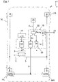
- the braking system on the front wheels VR and rear wheels RW each have a service brake B, which is integrated in a hydraulic circuit in which a hydraulic chamber 1 as a piston-cylinder unit realized pressure generator 3 via a hydraulic line 5 with a hydraulic chamber 7 of a brake cylinder 9 ( figure 5 ) connected is.
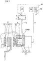
- the brake cylinder 9 is integrated in a cast brake caliper 10 .
- Stroke-adjustable brake pads 11 are arranged in the cast brake caliper 10 and interact with a brake disc 13 on the vehicle wheel.
- the pressure generator 3 can be controlled via a control logic 15 of a brake control system control device 16 .
- control logic 15 During driving operation, control logic 15 generates an actuating signal y 1 on the basis of a deceleration specification generated by the driver via a brake pedal 17, with which control signal y 1 the pressure generator 3 can be controlled.
- the pressure generator 3 depending on the actuating signal y 1 , the pressure on the brake cylinder piston 19 ( figure 5 ) of the brake cylinder 9 applied hydraulic pressure to bring the brake pads 11 in braking engagement with the brake disc 13.
- the cast brake caliper 10 acts as a combination brake caliper with an integrated parking brake actuator 21 ( figure 5 ).
- the parking brake actuator 21 is in the figure 5 constructed from a rotary drive motor 23 with a threaded spindle 25, which together with a pressure nut 27 form a screw drive. This protrudes in the figure 5 into the hydraulic chamber 7 of the brake cylinder 9.
- the pressure nut 27 moves in the figure 5 to the left, as a result of which the brake cylinder piston 19 together with the brake linings 11 is pressed against the brake disk 13 until braking engagement, specifically with the build-up of a clamping force with which the parking brake actuator 21 presses the brake linings 11 against the brake disk 13 with the brake cylinder piston 19 interposed.
- the control unit 16 has a second control module 24, which is used to control a DSE parking brake system, which will be described later. Coding takes place in the vehicle manufacturing plant or in a workshop before the vehicle is put into operation.
- the input module 30 On the basis of the coding signal K EPBI , the input module 30 generates an activation signal S T with which in FIG figure 1 the first control module 22 is activated in order to carry out a proper control of the EPBI parking system.
- the second control module 24 of the control device 16 remains deactivated.
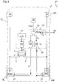
- the DSE parking brake system has a parking brake drum 31 which is arranged radially inside the cast brake caliper 10 and which interacts with brake shoes 33 .
- the brake shoes 33 can be brought into braking engagement with the inner circumference of the parking brake drum 31 via a parking brake actuator 35 .
- the parking brake actuator 35 can be controlled by the second control module 24 of the control unit 16 via control signals y 3 .
- the parking brake actuator 35 is assigned a position transmitter 37 (for example a Hall sensor) in order to determine a current position of the parking brake actuator 35 .
- the position transmitter 37 is in signal connection with the second control module 24.
- the second control module 24 has a sensor diagnosis module 39 .
- the sensor diagnostic module 39 recognizes that the position transmitter 37 is correctly installed and generates a corresponding installation signal V.
- the sensor diagnostic module 39 also recognizes that the position transmitter 37 is not installed. In this case, the sensor diagnostic module 39 generates a corresponding non-installation signal N
- the coding signal K DSE generated by the coding unit 29 at the signal input of an input component 30 of the control unit 16 .
- the input module 30 On the basis of the coding signal K DSE , the input module 30 generates an activation signal S T , with that in the figure 2 the second control module 24 is activated while the first control module 22 remains deactivated.
- the control unit 16 has a test unit 41 according to the invention.
- the checking unit 41 can be used to check whether the correct control module for the installed parking brake system is activated.
- Checking unit 41 carries out the interchange plausibility check on the basis of the blocking signal V, the non-blocking signal N and the coding signals K EPBI , K DSE .
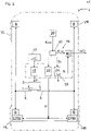
- the test unit 41 detects incorrect coding.
- checking unit 41 detects incorrect coding if the coding signal K DSE for activating the DSE parking brake system (works with position sensor 37) and the non-installation signal N (i.e. no position sensor 37 installed) is detected.
Landscapes
- Engineering & Computer Science (AREA)
- Transportation (AREA)
- Mechanical Engineering (AREA)
- Valves And Accessory Devices For Braking Systems (AREA)
- Regulating Braking Force (AREA)
Abstract
Description
- Die Erfindung betrifft eine Prüfanordnung zur Funktionsprüfung eines Bremsregelsystems in einem Fahrzeug nach dem Oberbegriff des Anspruches 1 sowie ein Verfahren zur Durchführung einer solchen Funktionsprüfung nach Anspruch 10.
- In einem Fahrzeug können die Betriebsbremsen der beiden Hinterräder zusätzlich jeweils ein Parkbremssystem aufweisen. Bei Premium-Fahrzeugen sind die folgenden beiden Arten von Parkbremssystemen im Einsatz: Erstens kann das Parkbremssystem einen Kombi-Bremssattel mit integriertem Parkbrems-Aktuator aufweisen, der von einem Steuergerät des Bremsregelsystems ansteuerbar ist. Alternativ dazu kann zweitens das Parkbremssystem eine Parkbremstrommel mit integriertem Parkbrems-Aktuator aufweisen, der ebenfalls vom Steuergerät des Bremsregelsystems ansteuerbar ist. Der verfügbare Stellweg des in der Parkbremstrommel integrierten Parkbrems-Aktuators ist im Vergleich zum im Kombi-Bremssattel integrierten Parkbrems-Aktuator stärker weglimitiert. Von daher ist der in der Parkbremstrommel integrierte Parkbrems-Aktuator zusätzlich mit einem Positionsgeber, zum Beispiel Hall-Sensor, verbaut. Der Positionsgeber ermittelt eine aktuelle Position des Parkbrems-Aktuator und ist in Signalverbindung mit dem Steuergerät des Bremsregelsystems.
- Mit Hilfe einer gattungsgemäßen Prüfanordnung wird eine Funktionsprüfung eines Bremsregelsystems in einem Fahrzeug durchgeführt. In dem Fahrzeug kann entweder ein erstes Parkbremssystem (das heißt Kombi-Bremssattel) oder ein zweites Parkbremssystem (das heißt Parkbremstrommel) verbaut sein. Das Bremsregelsystem weist ein Steuergerät mit einem ersten Steuermodul zur Ansteuerung des ersten Parkbremssystems und ein zweites Steuermodul zur Ansteuerung des zweiten Parkbremssystems auf. Zudem weist das Bremsregelsystem ein Ansteuerlogik für die hydraulisch arbeitenden Betriebsbremsen des Fahrzeugs auf.
- Die Ansteuerlogik, das erste Steuermodul und das zweite Steuermodul sind Software-Bestandteile eines Bremsregelsystem-Steuergeräts. Je nach Art des verbauten Parkbremssystems wird im fahrzeugbauenden Werk oder in einer Werkstatt eine Kodierung durchgeführt, bei der mittels einer Kodierungs-Einheit entweder das erste Steuermodul oder das zweite Steuermodul im Steuergerät aktiviert wird, um eine einwandfreie Ansteuerung des verbauten Parkbremssystems durchzuführen, während das nicht aktivierte Steuermodul funktionslos bleibt.
- Bei einer Falsch-Kodierung ergibt sich folgender Sachverhalt: Die Falsch-Kodierung, das heißt ein unbeabsichtigtes Vertauschen der Steuermodule, kann gegebenenfalls zu einer Bauteilbeschädigung im verbauten Parkbremssystem führen. Das erste Steuermodul und das zweite Steuermodul steuern nämlich die jeweils zugeordneten Parkbremssysteme mit unterschiedlicher Strom-/Spannungsstärke an.
- Aus der
EP 2 955 405 B1 ist ein Bremskomponenten-Austauschsystem bekannt. - Die Aufgabe der Erfindung besteht darin, eine Prüfanordnung zur Funktionsprüfung eines Fahrzeug-Bremsregelsystems bereitzustellen, bei der eine Bauteilbeschädigung im Parkbremssystem aufgrund einer Falsch-Kodierung in einfacher Weise vermieden werden kann.
- Die Aufgabe ist durch die Merkmale des Anspruches 1 oder 10 gelöst. Bevorzugte Weiterbildungen der Erfindung sind in den Unteransprüchen offenbart.
- Die Erfindung geht von einer Prüfanordnung zur Funktionsprüfung eines Bremsregelsystems in einem Fahrzeug aus. In dem Fahrzeug kann entweder ein erstes Parkbremssystem (das heißt Kombi-Bremssattel) oder ein zweites Parkbremssystem (das heißt Parktrommelbremse) verbaut sein. Das Bremsregelsystem weist ein Steuergerät mit einem ersten Steuermodul und einem zweiten Steuermodul auf. Eine Bauteilbeschädigung wird dann vermieden, wenn mit dem ersten Steuermodul das erste Parkbremssystem angesteuert wird, oder alternativ mit dem zweiten Steuermodul das zweite Parkbremssystem angesteuert wird.
- Je nach Art des im Fahrzeug verbauten Parkbremssystems wird im fahrzeugbauenden Werk oder in einer Werkstatt eine Kodierung durchgeführt, bei der eine Kodierungs-Einheit entweder das erste Steuermodul oder das zweite Steuermodul aktiviert, um eine einwandfreie Ansteuerung des verbauten Parkbremssystems durchzuführen. Das nicht aktivierte Steuermodul erhält dagegen keinen Steuerungs-Zugriff auf das verbaute Parkbremssystem, das heißt es bleibt funktionslos. Gemäß dem kennzeichnenden Teil des Anspruches 1 weist das Bremsregelsystem eine Prüfeinheit auf, mit der eine Vertauschplausibilisierung durchgeführt wird, um eine Falsch-Kodierung der Steuermodule zu erkennen. Bei Vorliegen einer solchen Falsch-Kodierung kann die Prüfeinheit ein Warnsignal generieren und/oder das verbaute Parkbremssystem funktionslos schalten, damit eine Bauteilbeschädigung des Parkbremssystems vermieden wird. Anhand der erfindungsgemäßen Vertauschplausibilisierung wird geprüft, ob das, für das verbaute Parkbremssystem richtige Steuermodul aktiviert ist oder nicht.
- Die Prüfeinheit bewertet eine Zuordnung des ersten Steuermoduls zum ersten Parkbremssystem als plausibel. In gleicher Weise bewertet die Prüfeinheit eine Zuordnung des zweiten Steuermoduls zum zweiten Parkbremssystem als plausibel. Im Gegensatz dazu bewertet die Prüfeinheit eine Zuordnung des zweiten Steuermoduls zum ersten Parkbremssystem als nicht plausibel, das heißt als Falsch-Kodierung. Analog dazu bewertet die Prüfeinheit eine Zuordnung des ersten Steuermoduls zum zweiten Parkbremssystem ebenfalls als nicht plausibel, das heißt als Falsch-Kodierung.
- In einer technischen Umsetzung kann die Prüfeinheit einen Ermittlungs-Baustein zur Bestimmung des (mittels der Kodierung) aktivierten Steuermoduls aufweisen. Zudem kann die Prüfeinheit einen Ermittlungs-Baustein zur Bestimmung des im Fahrzeug verbauten Parkbremssystems aufweisen. Auf der Grundlage der beiden Ermittlungs-Bausteine kann die Prüfeinheit die erfindungsgemäße Vertauschplausibilisierung durchführen.
- Nach erfolgter Feststellung und Dokumentation der Falsch-Kodierung wird bevorzugt eine Ansteuerung der Parkbremse verhindert. In diesem Fall sind jegliche Ansteuerungen der Parkbremse unterbunden, um einen effektiven Bauteilschutz bereitzustellen.
- Bei der Kodierung erzeugt die Kodierungs-Einheit ein Kodierungs-Signal, mit dem das Bremsregelsystem ansteuerbar ist. Auf der Grundlage des Kodierungs-Signals wird im Steuergerät des Bremsregelsystems eines der beiden Steuermodule aktiviert.
- In einer konkreten Ausführungsvariante kann das erste Parkbremssystem einen Kombi-Bremssattel mit integriertem Parkbrems-Aktuator aufweisen, der vom Bremsregelsystem-Steuergerät ansteuerbar ist. Das alternativ verbaubare, zweite Parkbremssystem kann eine Parkbremstrommel aufweisen, in der ein Parkbrems-Aktuator sowie ein Positionsgeber integriert ist. Mit Hilfe des Positionsgebers kann eine aktuelle Position des Parkbrems-Aktuators ermittelt werden. Der Positionsgeber ist in Signalverbindung mit dem zweiten Steuermodul, um die aktuelle Aktuator-Position zum zweiten Steuermodul zu leiten.
- Das zweite Steuermodul kann einen Sensordiagnose-Baustein aufweisen. Bei im Fahrzeug verbautem zweiten Parkbremssystem ist dessen Positionsgeber in Signalverbindung mit dem Sensordiagnose-Baustein bringbar. Mit Hilfe des Sensordiagnose-Bausteins ist ein einwandfreier Verbau des Positionsgebers erkennbar. In diesem Fall generiert der Sensordiagnose-Baustein ein entsprechendes Verbau-Signal. In gleicher Weise kann der Sensordiagnose-Baustein auch einen Nichtverbau des Positionsgebers erkennen und ein entsprechendes Nichtverbau-Signal generieren.
- In einer signaltechnisch einfachen Gestaltung kann die Prüfeinheit auf der Grundlage des Verbau-Signals, des Nichtverbau-Signals sowie des Kodierungs-Signals die erfindungsgemäße Vertauschplausibilisierung durchführen.
- In diesem Fall kann die Prüfeinheit bei Erfassung des Kodierungs-Signals zur Aktivierung des ersten Parkbremssystems (arbeitet ohne Positionsgeber) und bei Erfassung des Verbau-Signals (das heißt Positionsgeber ist an das Steuergerät angeschlossen) einen Falsch-Kodierung erkennen. Analog dazu kann die Prüfeinheit bei Erfassung des Kodierungs-Signals zur Aktivierung des zweiten Parkbremssystems (arbeitet mit Positionsgeber) und bei Erfassung des Nichtverbau-Signals (das heißt es ist kein Positionsgeber an das Steuergerät) eine Falsch-Kodierung erkennen.
- Nachfolgend ist ein Ausführungsbeispiel der Erfindung anhand der beigefügten Figuren beschrieben. Es zeigen:
- Fig. 1 und 2
- jeweils eine grob schematische Ansicht eines Fahrzeugs mit darin verbautem EPBI-Parkbremssystem (
Fig. 1 ), und mit darin verbautem DSE-Parkbremssystem (Fig. 2 ); - Fig. 3 und 4
- Ansichten entsprechend der
Fig. 1 und2 , in denen jeweils eine Falsch-Kodierung veranschaulicht ist; und - Fig. 5 und 6
- jeweils Prinzipskizzen eines EPBI-Parkbremssystems (
Fig. 5 ) und eines DSE-Parkbremssystems (Fig. 6 ). - In der
Figur 1 ist ein Bremssystem eines zweispurigen Fahrzeugs insoweit beschrieben, als es für das Verständnis der Erfindung erforderlich ist. Demnach weist das Bremssystem an den Vorderrädern VR und Hinterrädern HR jeweils eine Betriebsbremse B auf, die in einem Hydraulikkreis eingebunden ist, bei dem eine Hydraulikkammer 1 eines als Kolben-Zylinder-Einheit realisierten Druckerzeugers 3 über eine Hydraulikleitung 5 mit einer Hydraulikkammer 7 eines Bremszylinders 9 (Figur 5 ) verbunden ist. Der Bremszylinder 9 ist in einem Gußbremssattel 10 integriert. In dem Gußbremssattel 10 sind hubverstellbare Bremsbeläge 11 angeordnet, die mit einer fahrzeugradseitigen Bremsscheibe 13 zusammenwirken. Der Druckerzeuger 3 ist über eine Ansteuerlogik 15 eines Bremsregelsystem-Steuergerätes 16 ansteuerbar. Die Ansteuerlogik 15 generiert im Fahrbetrieb auf der Grundlage einer über ein Bremspedal 17 fahrerseitig erzeugten Verzögerungs-Vorgabe ein Stellsignal y1, mit dem der Druckerzeuger 3 ansteuerbar ist. Im Druckerzeuger 3 kann in Abhängigkeit von dem Stellsignal y1 der am Bremszylinderkolben 19 (Figur 5 ) des Bremszylinders 9 anliegende Hydraulikdruck erhöht werden, um die Bremsbeläge 11 im Bremseingriff mit der Bremsscheibe 13 zu bringen. - Wie aus der
Figur 1 hervorgeht, sind an den Hinterrädern HR des Fahrzeugs jeweils EPBI-Parkbremssysteme (EPBI = Elektrische Parkbremse Integriert) verbaut. Hierbei wirkt der Gußbremssattel 10 als ein Kombi-Bremssattel mit integriertem Parkbrems-Aktuator 21 (Figur 5 ). Dieser ist von einem ersten Steuermodul 22 der Steuereinheit 16 ansteuerbar. Der Parkbrems-Aktuator 21 ist in derFigur 5 aus einem Drehantriebmotor 23 mit einer Gewindespindel 25 aufgebaut, die zusammen mit einer Druckmutter 27 einen Gewindetrieb bilden. Dieser ragt in derFigur 5 in die Hydraulikkammer 7 des Bremszylinders 9 ein. Bei Betätigung des Parkbrems-Aktuators 21 fährt die Druckmutter 27 in derFigur 5 nach links, wodurch der Bremszylinderkolben 19 mitsamt Bremsbelägen 11 bis in Bremseingriff gegen die Bremsscheibe 13 gedrückt wird, und zwar unter Aufbau einer Spannkraft, mit der der Parkbrems-Aktuator 21 unter Zwischenlage des Bremszylinderkolbens 19 die Bremsbeläge 11 gegen die Bremsscheibe 13 drückt. - Wie aus der
Figur 1 weiter hervorgeht, weist die Steuereinheit 16 neben der Ansteuerlogik 15 und dem ersten Steuermodul 22 ein zweites Steuermodul 24 auf, die zur Ansteuerung eines später beschriebenen DSE-Parkbremssystems dient. Im fahrzeugbauenden Werk oder in einer Werkstatt erfolgt vor der Fahrzeug-Inbetriebnahme eine Kodierung. Bei der Kodierung liegt das von der Kodierungs-Einheit 29 erzeugte Kodierungs-Signal KEPBI am Signaleingang eines Eingabe-Bausteins 30 des Steuergeräts 16 an. Auf der Grundlage des Kodierungs-Signals KEPBI erzeugt der Eingabe-Baustein 30 ein Aktivierungssignal ST, mit dem in derFigur 1 das erste Steuermodul 22 aktiviert wird, um eine einwandfreie Ansteuerung des EPBI-Parksystems durchzuführen. Das zweite Steuermodul 24 des Steuergeräts 16 bleibt deaktiviert. - Alternativ dazu ist in der
Figur 2 an den Hinterrädern HR des Fahrzeugs jeweils ein DSE-Parkbremssystem (DSE = Dual-Servo-Electric) verbaut. In derFigur 6 weist das DSE-Parkbremssystem eine radial innerhalb des Gußbremssattels 10 angeordnete Parkbremstrommel 31 auf, die mit Bremsbacken 33 zusammenwirkt. Die Bremsbacken 33 können über einen Parkbrems-Aktuator 35 in Bremseingriff mit dem Innenumfang der Parkbremstrommel 31 gebracht werden. Der Parkbrems-Aktuator 35 ist über Stellsignale y3 vom zweiten Steuermodul 24 der Steuereinheit 16 ansteuerbar. Zudem ist dem Parkbrems-Aktuator 35 ein Positionsgeber 37 (zum Beispiel Hall-Sensor) zugeordnet, um eine aktuelle Position des Parkbrems-Aktuators 35 zu ermitteln. Der Positionsgeber 37 ist in Signalverbindung mit dem zweiten Steuermodul 24. - Wie aus den Figuren weiter hervorgeht, weist das zweite Steuermodul 24 einen Sensordiagnose-Baustein 39 auf. Der Sensordiagnose-Baustein 39 erkennt einen einwandfreien Verbau des Positionsgebers 37 und generiert ein entsprechendes Verbau-Signal V. Alternativ dazu erkennt der Sensordiagnose-Baustein 39 auch einen Nichtverbau des Positionsgebers 37. In diesem Fall generiert der Sensordiagnose-Baustein 39 ein entsprechendes Nichtverbau-Signal N.
- Bei der Kodierung liegt gemäß der
Figur 2 das von der Kodierungs-Einheit 29 erzeugte Kodierungs-Signal KDSE am Signaleingang eines Eingabe-Bausteins 30 des Steuergeräts 16 an. Auf der Grundlage des Kodierungs-Signals KDSE erzeugt der Eingabe-Baustein 30 ein Aktivierungssignal ST, mit dem in derFigur 2 das zweite Steuermodul 24 aktiviert wird, während des erste Steuermodul 22 deaktiviert bleibt. - Um eine Falsch-Kodierung der Steuermodule 22, 24 zu dokumentieren, weist die Steuereinheit 16 eine erfindungsgemäße Prüfeinheit 41 auf. Mittels der Prüfeinheit 41 ist eine Vertauschplausibilisierung durchführbar, anhand der geprüft wird, ob das, für das verbaute Parkbremssystem richtige Steuermodul aktiviert ist. Die Prüfeinheit 41 führt die Vertauschplausibilisierung auf der Grundlage des Verbau-Signals V, des Nichtverbau-Signals N sowie der Kodierungs-Signale KEPBI, KDSE durch. Bei Erfassung des Kodierungs-Signals KEPBI zur Aktivierung des EPBI-Parkbremssystems (arbeitet ohne Positionsgeber 37) und bei Erfassung des Verbau-Signals V (das heißt Positionsgeber 37 ist verbaut) erkennt die Prüfeinheit 41 eine Falsch-Kodierung. In gleicher Weise erkennt die Prüfeinheit 41 eine Falsch-Kodierung, sofern das Kodierungs-Signal KDSE zur Aktivierung des DSE-Parkbremssystems (arbeitet mit Positionsgeber 37) und das Nichtverbau-Signal N (das heißt kein Positionsgeber 37 verbaut) erfasst wird.
-
- 1
- Hydraulikkammer
- 3
- Druckerzeuger
- 5
- Hydraulikleitung
- 7
- Hydraulikkammer
- 9
- Bremszylinder
- 10
- Gußbremssattel
- 11
- Bremsbeläge
- 13
- Bremsscheibe
- 15
- Ansteuerlogik
- 16
- Steuergerät
- 17
- Bremspedal
- 19
- Bremszylinderkolben
- 21
- Parkbrems-Aktuator
- 22
- erstes Steuermodul
- 23
- Drehantriebmotor
- 24
- zweites Steuermodul
- 25
- Gewindespindel
- 27
- Druckmutter
- 29
- Kodierungs-Einheit
- 30
- Eingabe-Baustein
- 31
- Parkbremstrommel
- 33
- Bremsbacken
- 35
- Parkbrems-Aktuator
- 37
- Positionsgeber
- 39
- Sensordiagnose-Baustein
- 41
- Prüfeinheit
- y1, y2, y3
- Stellsignale
- B
- Betriebsbremse
- EPBI
- erstes Parkbremssystem
- DSE
- zweites Parkbremssystem
- KEPBI
- erstes Kodierungs-Signal
- KDSE
- zweites Kodierungs-Signal
- V
- Verbau-Signal
- N
- Nichtverbau-Signal
- SA
- Aktivierungssignal
- niO
- Falsch-Kodierung
- iO
- Richtig-Kodierung
- VR
- Vorderräder
- HR
- Hinterräder
Claims (10)
- Prüfanordnung zur Funktionsprüfung eines Bremsregelsystems in einem Fahrzeug, in dem entweder ein erstes Parkbremssystem (EPBI) oder ein zweites Parkbremssystem (DSE) verbaubar ist, wobei das Bremsregelsystem ein Steuergerät (16) mit einem ersten Steuermodul (22) zur Ansteuerung des ersten Parkbremssystems (EPBI) und mit einem zweiten Steuermodul (24) zur Ansteuerung des zweiten Parkbremssystems (DSE) aufweist, und wobei entweder das erste Steuermodul (22) oder das zweite Steuermodul (24) mittels einer Kodierungs-Einheit (29) aktivierbar ist, um eine Ansteuerung des zugeordneten Parkbremssystems durchzuführen, während das nicht aktivierte Steuermodul funktionslos bleibt,
dadurch gekennzeichnet,
dass das Bremsregelsystem eine Prüfeinheit (41) aufweist, mit der eine Vertauschplausibilisierung durchführbar ist, anhand der prüfbar ist, ob das, für das verbaute Parkbremssystem (EPBI, DSE) richtige Steuermodul (22, 24) aktiviert ist. - Prüfanordnung nach Anspruch 1, dadurch gekennzeichnet, dass die Prüfeinheit (41) eine Zuordnung des ersten Steuermoduls (22) zum ersten Parkbremssystem (EPBI) bzw. eine Zuordnung des zweiten Steuermoduls (24) zum zweiten Parkbremssystem (DSE) als plausibel bewertet, und/oder dass die Prüfeinheit (41) eine Zuordnung des zweiten Steuermoduls (24) zum ersten Parkbremssystem (EPBI) bzw. eine Zuordnung des ersten Steuermoduls (22) zum zweiten Parkbremssystem (DSE) als nicht plausibel, das heißt als Falsch-Kodierung (niO), bewertet, und dass insbesondere nach erfolgter Feststellung und Dokumentation der Falsch-Kodierung (niO) eine Ansteuerung der Parkbremse auch effektiv verhindert ist, und/oder dass nach erfolgter Feststellung und Dokumentation der Falsch-Kodierung (niO) jegliche Ansteuerungen der Parkbremse unterbunden werden, um einen effektiven Bauteilschutz bereitzustellen.
- Prüfanordnung nach Anspruch 1 oder 2, dadurch gekennzeichnet, dass die Prüfeinheit (41) einen Ermittlungs-Baustein (30) zur Bestimmung des aktivierten Steuermoduls (22, 24) aufweist und einen Ermittlungs-Baustein (39) zur Bestimmung des im Fahrzeug verbauten Parkbremssystems aufweist, und dass die Prüfeinheit (41) auf der Grundlage der beiden Ermittlungs-Bausteine (30, 39) die Vertauschplausibilisierung durchführt.
- Prüfanordnung nach Anspruch 1, 2 oder 3, dadurch gekennzeichnet, dass bei der Kodierung die Kodierungs-Einheit (29) ein Kodierungs-Signal (KEPBI, KDSE) erzeugt, mit dem das Steuergerät (16) des Bremsregelsystem ansteuerbar ist, und dass auf der Grundlage des Kodierungs-Signals (KEPBI, KDSE) eines der Steuermodule (22, 24) des Steuergeräts (16) aktivierbar ist.
- Prüfanordnung nach einem der vorhergehenden Ansprüche, dadurch gekennzeichnet, dass das erste Parkbremssystem (EPBI) einen Kombi-Bremssattel (10) mit integriertem Parkbrems-Aktuator (21) aufweist, der vom Steuergerät (16) ansteuerbar ist, und/oder dass das zweite Parkbremssystem (DSE) eine Parkbremstrommel (31) mit integriertem Parkbrems-Aktuator (35) sowie mit einem Positionsgeber (37) aufweist, um eine aktuelle Position des Parkbrems-Aktuators (35) zu ermitteln, und/oder dass im verbauten Zustand der Positionsgeber (37) in Signalverbindung mit dem zweiten Steuermodul (24) ist.
- Prüfanordnung nach Anspruch 5, dadurch gekennzeichnet, dass das zweite Steuermodul (24) einen Sensordiagnose-Baustein (39) aufweist, und dass bei im Fahrzeug verbautem zweiten Parkbremssystem (DSE) der Positionsgeber (37) in Signalverbindung mit dem Sensordiagnose-Baustein (39) ist, und dass der Sensordiagnose-Baustein (39) einen einwandfreien Verbau des Positionsgebers (37) erkennt und ein entsprechendes Verbau-Signal (V) generiert, oder dass der Sensordiagnose-Baustein (39) einen Nichtverbau des Positionsgebers (37) erkennt und ein entsprechendes Nichtverbau-Signal (N) generiert.
- Prüfanordnung nach Anspruch 6, dadurch gekennzeichnet, dass die Vertauschplausibilisierung auf der Grundlage des Verbau-Signals (V), des Nichtverbau-Signals (N) sowie der Kodierungs-Signale (KEPBI, KDSE) erfolgt.
- Prüfanordnung nach Anspruch 7, dadurch gekennzeichnet, dass die Prüfeinheit (41) bei Erfassung des Kodierungs-Signals (KEPBI) zur Aktivierung des ersten Parkbremssystems (EPBI) und bei Erfassung des Verbau-Signals (V), das den Verbau eines Positionsgebers (37) anzeigt, eine Falsch-Kodierung (niO) erkennt.
- Prüfanordnung nach Anspruch 7 oder 8, dadurch gekennzeichnet, dass die Prüfeinheit (41) bei Erfassung des Kodierungs-Signals (KDSE) zur Aktivierung des zweiten Parkbremssystems (DSE) und bei Erfassung des Nichtverbau-Signals (N), das den Nicht-Verbau eines Positionsgebers (37) anzeigt, eine Falsch-Kodierung (niO) erkennt.
- Verfahren zur Funktionsprüfung eines Bremsregelsystems in einem Fahrzeug mittels einer Prüfanordnung nach einem der vorhergehenden Ansprüche, in dem entweder ein erstes Parkbremssystem (EPBI) oder ein zweites Parkbremssystem (DSE) verbaubar ist, wobei das Bremsregelsystem ein Steuergerät (16) mit einem ersten Steuermodul (22) zur Ansteuerung des ersten Parkbremssystems (EPBI) und mit einem zweiten Steuermodul (24) zur Ansteuerung des zweiten Parkbremssystems (DSE) aufweist, und wobei entweder das erste Steuermodul (22) oder das zweite Steuermodul (24) mittels einer Kodierungs-Einheit (29) aktiviert wird, um eine Ansteuerung des zugeordneten Parkbremssystems durchzuführen, während das nicht aktivierte Steuermodul funktionslos bleibt,
dadurch gekennzeichnet,
dass in dem Bremsregelsystem eine Vertauschplausibilisierung durchführgeführt wird, anhand der geprüft wird, ob das, für das verbaute Parkbremssystem richtige Steuermodul aktiviert ist.
Applications Claiming Priority (1)
| Application Number | Priority Date | Filing Date | Title |
|---|---|---|---|
| DE102021118337.5A DE102021118337A1 (de) | 2021-07-15 | 2021-07-15 | Prüfanordnung zur Funktionsprüfung eines Fahrzeug-Bremsregelsystems |
Publications (2)
| Publication Number | Publication Date |
|---|---|
| EP4119406A1 true EP4119406A1 (de) | 2023-01-18 |
| EP4119406B1 EP4119406B1 (de) | 2024-02-21 |
Family
ID=82016270
Family Applications (1)
| Application Number | Title | Priority Date | Filing Date |
|---|---|---|---|
| EP22178189.1A Active EP4119406B1 (de) | 2021-07-15 | 2022-06-09 | Prüfanordnung zur funktionsprüfung eines fahrzeug-bremsregelsystems |
Country Status (4)
| Country | Link |
|---|---|
| US (1) | US12552359B2 (de) |
| EP (1) | EP4119406B1 (de) |
| CN (1) | CN115610400B (de) |
| DE (1) | DE102021118337A1 (de) |
Families Citing this family (1)
| Publication number | Priority date | Publication date | Assignee | Title |
|---|---|---|---|---|
| DE102023210463A1 (de) * | 2023-10-24 | 2025-04-24 | Robert Bosch Gesellschaft mit beschränkter Haftung | Verfahren und Steuergerät |
Citations (7)
| Publication number | Priority date | Publication date | Assignee | Title |
|---|---|---|---|---|
| DE19751431A1 (de) * | 1997-11-20 | 1999-07-15 | Itt Mfg Enterprises Inc | Elektromechanische Feststellbremse |
| US20150291279A1 (en) * | 2013-11-27 | 2015-10-15 | Airbus Operations Limited | Aircraft electric braking system |
| EP2955405B1 (de) | 2014-06-10 | 2017-02-01 | Aktiebolaget SKF | Wälzlager mit Mitteln zum winkeligen Einstellen des Innenrings gegenüber dem Außenring |
| US10131329B1 (en) * | 2017-06-23 | 2018-11-20 | Goodrich, Corporation | Brake system power arbitration |
| CN109677388A (zh) * | 2019-02-03 | 2019-04-26 | 上海蔚来汽车有限公司 | 电子驻车系统、包括该电子驻车系统的车辆及控制方法 |
| EP3741635A1 (de) * | 2019-05-22 | 2020-11-25 | Volkswagen Aktiengesellschaft | Bremssteuersystem |
| DE102019215536A1 (de) * | 2019-10-10 | 2021-04-15 | Robert Bosch Gmbh | Fahrzeug-Feststellbremse mit einem ersten und einem zweiten elektrischen Bremsmotor |
Family Cites Families (12)
| Publication number | Priority date | Publication date | Assignee | Title |
|---|---|---|---|---|
| JP2000118372A (ja) * | 1998-10-09 | 2000-04-25 | Toyota Motor Corp | 車両用ブレーキシステム |
| US6175798B1 (en) * | 1999-12-03 | 2001-01-16 | Kelsey-Hayes Company | Algorithm for verification of correct ABS controller installation |
| DE102007029632A1 (de) * | 2006-06-27 | 2008-01-10 | Continental Teves Ag & Co. Ohg | Feststellbremsanlage für Kraftfahrzeuge |
| DE102007031819A1 (de) | 2007-07-07 | 2009-01-08 | Daimler Ag | Feststellbremssystem für ein Kraftfahrzeug |
| DE102008003379A1 (de) | 2008-01-07 | 2009-07-09 | Wabco Gmbh | Bremsanlage für ein Fahrzeug sowie Bremspedaleinrichtung für eine derartige Bremsanlage |
| DE102011110892B4 (de) * | 2011-08-01 | 2013-07-18 | Günter Fendt | Fahrzeug-Bremssystem, sowie Verfahren hierfür |
| EP2955408B1 (de) | 2014-06-13 | 2019-11-20 | Meritor Heavy Vehicle Braking Systems (UK) Limited | Bremskomponentenaustauschsystem und -verfahren |
| DE102015219001A1 (de) * | 2015-10-01 | 2017-04-06 | Continental Teves Ag & Co. Ohg | Bremssystem und Verfahren zum Betreiben eines Bremssystems |
| DE102016222045A1 (de) * | 2016-11-10 | 2018-05-17 | Robert Bosch Gmbh | Verfahren und Vorrichtung zum Betreiben einer Bremsanlage eines Kraftfahrzeugs, Bremsanlage |
| DE102017204157A1 (de) | 2017-03-14 | 2018-09-20 | Bayerische Motoren Werke Aktiengesellschaft | Bremsregelsystem einer elektrohydraulischen Bremsanlage |
| DE102018203776A1 (de) * | 2018-03-13 | 2019-09-19 | Continental Teves Ag & Co. Ohg | Verfahren zum Aktivieren einer Parkbremsfunktion und Bremssystem |
| CN109080596A (zh) * | 2018-08-23 | 2018-12-25 | 杭州容大智造科技有限公司 | 具有阻力器控制装置的安全驻车系统 |
-
2021
- 2021-07-15 DE DE102021118337.5A patent/DE102021118337A1/de not_active Withdrawn
-
2022
- 2022-06-09 EP EP22178189.1A patent/EP4119406B1/de active Active
- 2022-07-01 CN CN202210773849.7A patent/CN115610400B/zh active Active
- 2022-07-07 US US17/859,083 patent/US12552359B2/en active Active
Patent Citations (7)
| Publication number | Priority date | Publication date | Assignee | Title |
|---|---|---|---|---|
| DE19751431A1 (de) * | 1997-11-20 | 1999-07-15 | Itt Mfg Enterprises Inc | Elektromechanische Feststellbremse |
| US20150291279A1 (en) * | 2013-11-27 | 2015-10-15 | Airbus Operations Limited | Aircraft electric braking system |
| EP2955405B1 (de) | 2014-06-10 | 2017-02-01 | Aktiebolaget SKF | Wälzlager mit Mitteln zum winkeligen Einstellen des Innenrings gegenüber dem Außenring |
| US10131329B1 (en) * | 2017-06-23 | 2018-11-20 | Goodrich, Corporation | Brake system power arbitration |
| CN109677388A (zh) * | 2019-02-03 | 2019-04-26 | 上海蔚来汽车有限公司 | 电子驻车系统、包括该电子驻车系统的车辆及控制方法 |
| EP3741635A1 (de) * | 2019-05-22 | 2020-11-25 | Volkswagen Aktiengesellschaft | Bremssteuersystem |
| DE102019215536A1 (de) * | 2019-10-10 | 2021-04-15 | Robert Bosch Gmbh | Fahrzeug-Feststellbremse mit einem ersten und einem zweiten elektrischen Bremsmotor |
Also Published As
| Publication number | Publication date |
|---|---|
| US20230023343A1 (en) | 2023-01-26 |
| EP4119406B1 (de) | 2024-02-21 |
| CN115610400A (zh) | 2023-01-17 |
| DE102021118337A1 (de) | 2023-01-19 |
| US12552359B2 (en) | 2026-02-17 |
| CN115610400B (zh) | 2025-09-05 |
Similar Documents
| Publication | Publication Date | Title |
|---|---|---|
| EP2520817B1 (de) | Verfahren und Vorrichtung zum Überwachen des Bremsbelagverschleißes und Lüftspiels einer Betriebsbremse in Kraftfahrzeugen | |
| EP3044056B2 (de) | Fahrassistenzsystem mit gesteigerter ausfallsicherheit und verfügbarkeit | |
| EP3580101B1 (de) | Bremsmotor-steuergerät, bremssystem für ein fahrzeug mit einem elektrischen bremsmotor und verfahren zur ansteuerung des bremsmotorsteuergeräts | |
| DE102011110892B4 (de) | Fahrzeug-Bremssystem, sowie Verfahren hierfür | |
| DE102018205829A1 (de) | Fahrzeug-Feststellbremse | |
| DE102017214455A1 (de) | Verfahren zum Betreiben eines Bremssystems mit einer automatisierten Feststellbremse | |
| DE102020113864A1 (de) | Kraftwagen und Verfahren zum Betreiben eines Kraftwagens | |
| DE102011003183A1 (de) | Verfahren zur Überwachung der Funktion einer Feststellbremse in einem Fahrzeug | |
| DE112019000912T5 (de) | Elektrische Bremse und Steuervorrichtung | |
| DE102019200955A1 (de) | Verfahren zur Aktivierung und Deaktivierung eines Steuergeräts | |
| DE102016215293A1 (de) | Verfahren zur Ermittlung einer Leckage in einem hydraulischen Bremssystem | |
| EP4119406B1 (de) | Prüfanordnung zur funktionsprüfung eines fahrzeug-bremsregelsystems | |
| DE10325650A1 (de) | Bremsvorrichtung und -verfahren für ein Fahrzeug | |
| WO2012065769A2 (de) | System sowie verfahren zur bremskreisausfallerkennung | |
| DE102018219443B4 (de) | Verfahren zum Erkennen von Anschlussfehlern an einer Kraftfahrzeugbremsanlage und Steuergerät für eine Kraftfahrzeugbremsanlage | |
| DE102022104852A1 (de) | Bremssystem, Fahrzeug und Verfahren zum Betreiben eines Bremssystems | |
| DE10011635B4 (de) | Verfahren zur Feststellung der Einbauposition von bremskrafterzeugenden Einheiten einer elektrommechanischen Kraftfahrzeug-Bremsanlage | |
| EP4347337A2 (de) | Elektromechanisches bremssystem für ein kraftfahrzeug, verfahren | |
| EP1564096B1 (de) | Überprüfung der Funktionsfähigkeit einer Feststellbremse durch Auswertung der Raddrehzahlen | |
| WO2017021061A1 (de) | Verfahren zum überprüfen der parkbremskraft in einem fahrzeug | |
| EP1768880B1 (de) | Verfahren zur steuerung einer fahrzeugbremse mit einer bremsbereitschaftsfunktion | |
| WO2008138752A1 (de) | Stop and go betrieb einer elektronischen parkbremse | |
| DE102016224836A1 (de) | Verfahren zur Überwachung eines Bremssystems mit elektromechanischer Bremsvorrichtung | |
| DE102020118609A1 (de) | Verfahren zur Verbauprüfung zumindest einen Parkbrems-Aktuators in einer Fahrzeug-Bremsanlage | |
| DE102005014242A1 (de) | Feststellbremse mit Notlösealgorithmus |
Legal Events
| Date | Code | Title | Description |
|---|---|---|---|
| PUAI | Public reference made under article 153(3) epc to a published international application that has entered the european phase |
Free format text: ORIGINAL CODE: 0009012 |
|
| STAA | Information on the status of an ep patent application or granted ep patent |
Free format text: STATUS: THE APPLICATION HAS BEEN PUBLISHED |
|
| AK | Designated contracting states |
Kind code of ref document: A1 Designated state(s): AL AT BE BG CH CY CZ DE DK EE ES FI FR GB GR HR HU IE IS IT LI LT LU LV MC MK MT NL NO PL PT RO RS SE SI SK SM TR |
|
| P01 | Opt-out of the competence of the unified patent court (upc) registered |
Effective date: 20230529 |
|
| STAA | Information on the status of an ep patent application or granted ep patent |
Free format text: STATUS: REQUEST FOR EXAMINATION WAS MADE |
|
| 17P | Request for examination filed |
Effective date: 20230718 |
|
| RBV | Designated contracting states (corrected) |
Designated state(s): AL AT BE BG CH CY CZ DE DK EE ES FI FR GB GR HR HU IE IS IT LI LT LU LV MC MK MT NL NO PL PT RO RS SE SI SK SM TR |
|
| GRAP | Despatch of communication of intention to grant a patent |
Free format text: ORIGINAL CODE: EPIDOSNIGR1 |
|
| STAA | Information on the status of an ep patent application or granted ep patent |
Free format text: STATUS: GRANT OF PATENT IS INTENDED |
|
| INTG | Intention to grant announced |
Effective date: 20231128 |
|
| GRAS | Grant fee paid |
Free format text: ORIGINAL CODE: EPIDOSNIGR3 |
|
| GRAA | (expected) grant |
Free format text: ORIGINAL CODE: 0009210 |
|
| STAA | Information on the status of an ep patent application or granted ep patent |
Free format text: STATUS: THE PATENT HAS BEEN GRANTED |
|
| AK | Designated contracting states |
Kind code of ref document: B1 Designated state(s): AL AT BE BG CH CY CZ DE DK EE ES FI FR GB GR HR HU IE IS IT LI LT LU LV MC MK MT NL NO PL PT RO RS SE SI SK SM TR |
|
| REG | Reference to a national code |
Ref country code: GB Ref legal event code: FG4D Free format text: NOT ENGLISH |
|
| REG | Reference to a national code |
Ref country code: CH Ref legal event code: EP |
|
| REG | Reference to a national code |
Ref country code: DE Ref legal event code: R096 Ref document number: 502022000522 Country of ref document: DE |
|
| REG | Reference to a national code |
Ref country code: IE Ref legal event code: FG4D Free format text: LANGUAGE OF EP DOCUMENT: GERMAN |
|
| REG | Reference to a national code |
Ref country code: LT Ref legal event code: MG9D |
|
| REG | Reference to a national code |
Ref country code: NL Ref legal event code: MP Effective date: 20240221 |
|
| PG25 | Lapsed in a contracting state [announced via postgrant information from national office to epo] |
Ref country code: IS Free format text: LAPSE BECAUSE OF FAILURE TO SUBMIT A TRANSLATION OF THE DESCRIPTION OR TO PAY THE FEE WITHIN THE PRESCRIBED TIME-LIMIT Effective date: 20240621 |
|
| PG25 | Lapsed in a contracting state [announced via postgrant information from national office to epo] |
Ref country code: LT Free format text: LAPSE BECAUSE OF FAILURE TO SUBMIT A TRANSLATION OF THE DESCRIPTION OR TO PAY THE FEE WITHIN THE PRESCRIBED TIME-LIMIT Effective date: 20240221 |
|
| PG25 | Lapsed in a contracting state [announced via postgrant information from national office to epo] |
Ref country code: GR Free format text: LAPSE BECAUSE OF FAILURE TO SUBMIT A TRANSLATION OF THE DESCRIPTION OR TO PAY THE FEE WITHIN THE PRESCRIBED TIME-LIMIT Effective date: 20240522 |
|
| PG25 | Lapsed in a contracting state [announced via postgrant information from national office to epo] |
Ref country code: NL Free format text: LAPSE BECAUSE OF FAILURE TO SUBMIT A TRANSLATION OF THE DESCRIPTION OR TO PAY THE FEE WITHIN THE PRESCRIBED TIME-LIMIT Effective date: 20240221 Ref country code: HR Free format text: LAPSE BECAUSE OF FAILURE TO SUBMIT A TRANSLATION OF THE DESCRIPTION OR TO PAY THE FEE WITHIN THE PRESCRIBED TIME-LIMIT Effective date: 20240221 Ref country code: RS Free format text: LAPSE BECAUSE OF FAILURE TO SUBMIT A TRANSLATION OF THE DESCRIPTION OR TO PAY THE FEE WITHIN THE PRESCRIBED TIME-LIMIT Effective date: 20240521 |
|
| PG25 | Lapsed in a contracting state [announced via postgrant information from national office to epo] |
Ref country code: ES Free format text: LAPSE BECAUSE OF FAILURE TO SUBMIT A TRANSLATION OF THE DESCRIPTION OR TO PAY THE FEE WITHIN THE PRESCRIBED TIME-LIMIT Effective date: 20240221 |
|
| PG25 | Lapsed in a contracting state [announced via postgrant information from national office to epo] |
Ref country code: RS Free format text: LAPSE BECAUSE OF FAILURE TO SUBMIT A TRANSLATION OF THE DESCRIPTION OR TO PAY THE FEE WITHIN THE PRESCRIBED TIME-LIMIT Effective date: 20240521 Ref country code: NO Free format text: LAPSE BECAUSE OF FAILURE TO SUBMIT A TRANSLATION OF THE DESCRIPTION OR TO PAY THE FEE WITHIN THE PRESCRIBED TIME-LIMIT Effective date: 20240521 Ref country code: NL Free format text: LAPSE BECAUSE OF FAILURE TO SUBMIT A TRANSLATION OF THE DESCRIPTION OR TO PAY THE FEE WITHIN THE PRESCRIBED TIME-LIMIT Effective date: 20240221 Ref country code: LT Free format text: LAPSE BECAUSE OF FAILURE TO SUBMIT A TRANSLATION OF THE DESCRIPTION OR TO PAY THE FEE WITHIN THE PRESCRIBED TIME-LIMIT Effective date: 20240221 Ref country code: IS Free format text: LAPSE BECAUSE OF FAILURE TO SUBMIT A TRANSLATION OF THE DESCRIPTION OR TO PAY THE FEE WITHIN THE PRESCRIBED TIME-LIMIT Effective date: 20240621 Ref country code: HR Free format text: LAPSE BECAUSE OF FAILURE TO SUBMIT A TRANSLATION OF THE DESCRIPTION OR TO PAY THE FEE WITHIN THE PRESCRIBED TIME-LIMIT Effective date: 20240221 Ref country code: GR Free format text: LAPSE BECAUSE OF FAILURE TO SUBMIT A TRANSLATION OF THE DESCRIPTION OR TO PAY THE FEE WITHIN THE PRESCRIBED TIME-LIMIT Effective date: 20240522 Ref country code: FI Free format text: LAPSE BECAUSE OF FAILURE TO SUBMIT A TRANSLATION OF THE DESCRIPTION OR TO PAY THE FEE WITHIN THE PRESCRIBED TIME-LIMIT Effective date: 20240221 Ref country code: ES Free format text: LAPSE BECAUSE OF FAILURE TO SUBMIT A TRANSLATION OF THE DESCRIPTION OR TO PAY THE FEE WITHIN THE PRESCRIBED TIME-LIMIT Effective date: 20240221 Ref country code: BG Free format text: LAPSE BECAUSE OF FAILURE TO SUBMIT A TRANSLATION OF THE DESCRIPTION OR TO PAY THE FEE WITHIN THE PRESCRIBED TIME-LIMIT Effective date: 20240221 |
|
| PG25 | Lapsed in a contracting state [announced via postgrant information from national office to epo] |
Ref country code: PT Free format text: LAPSE BECAUSE OF FAILURE TO SUBMIT A TRANSLATION OF THE DESCRIPTION OR TO PAY THE FEE WITHIN THE PRESCRIBED TIME-LIMIT Effective date: 20240621 Ref country code: PL Free format text: LAPSE BECAUSE OF FAILURE TO SUBMIT A TRANSLATION OF THE DESCRIPTION OR TO PAY THE FEE WITHIN THE PRESCRIBED TIME-LIMIT Effective date: 20240221 |
|
| PG25 | Lapsed in a contracting state [announced via postgrant information from national office to epo] |
Ref country code: SE Free format text: LAPSE BECAUSE OF FAILURE TO SUBMIT A TRANSLATION OF THE DESCRIPTION OR TO PAY THE FEE WITHIN THE PRESCRIBED TIME-LIMIT Effective date: 20240221 Ref country code: PT Free format text: LAPSE BECAUSE OF FAILURE TO SUBMIT A TRANSLATION OF THE DESCRIPTION OR TO PAY THE FEE WITHIN THE PRESCRIBED TIME-LIMIT Effective date: 20240621 Ref country code: PL Free format text: LAPSE BECAUSE OF FAILURE TO SUBMIT A TRANSLATION OF THE DESCRIPTION OR TO PAY THE FEE WITHIN THE PRESCRIBED TIME-LIMIT Effective date: 20240221 Ref country code: LV Free format text: LAPSE BECAUSE OF FAILURE TO SUBMIT A TRANSLATION OF THE DESCRIPTION OR TO PAY THE FEE WITHIN THE PRESCRIBED TIME-LIMIT Effective date: 20240221 |
|
| PG25 | Lapsed in a contracting state [announced via postgrant information from national office to epo] |
Ref country code: DK Free format text: LAPSE BECAUSE OF FAILURE TO SUBMIT A TRANSLATION OF THE DESCRIPTION OR TO PAY THE FEE WITHIN THE PRESCRIBED TIME-LIMIT Effective date: 20240221 |
|
| PG25 | Lapsed in a contracting state [announced via postgrant information from national office to epo] |
Ref country code: SM Free format text: LAPSE BECAUSE OF FAILURE TO SUBMIT A TRANSLATION OF THE DESCRIPTION OR TO PAY THE FEE WITHIN THE PRESCRIBED TIME-LIMIT Effective date: 20240221 |
|
| PG25 | Lapsed in a contracting state [announced via postgrant information from national office to epo] |
Ref country code: CZ Free format text: LAPSE BECAUSE OF FAILURE TO SUBMIT A TRANSLATION OF THE DESCRIPTION OR TO PAY THE FEE WITHIN THE PRESCRIBED TIME-LIMIT Effective date: 20240221 Ref country code: EE Free format text: LAPSE BECAUSE OF FAILURE TO SUBMIT A TRANSLATION OF THE DESCRIPTION OR TO PAY THE FEE WITHIN THE PRESCRIBED TIME-LIMIT Effective date: 20240221 |
|
| PG25 | Lapsed in a contracting state [announced via postgrant information from national office to epo] |
Ref country code: SK Free format text: LAPSE BECAUSE OF FAILURE TO SUBMIT A TRANSLATION OF THE DESCRIPTION OR TO PAY THE FEE WITHIN THE PRESCRIBED TIME-LIMIT Effective date: 20240221 |
|
| PG25 | Lapsed in a contracting state [announced via postgrant information from national office to epo] |
Ref country code: SM Free format text: LAPSE BECAUSE OF FAILURE TO SUBMIT A TRANSLATION OF THE DESCRIPTION OR TO PAY THE FEE WITHIN THE PRESCRIBED TIME-LIMIT Effective date: 20240221 Ref country code: SK Free format text: LAPSE BECAUSE OF FAILURE TO SUBMIT A TRANSLATION OF THE DESCRIPTION OR TO PAY THE FEE WITHIN THE PRESCRIBED TIME-LIMIT Effective date: 20240221 Ref country code: RO Free format text: LAPSE BECAUSE OF FAILURE TO SUBMIT A TRANSLATION OF THE DESCRIPTION OR TO PAY THE FEE WITHIN THE PRESCRIBED TIME-LIMIT Effective date: 20240221 Ref country code: EE Free format text: LAPSE BECAUSE OF FAILURE TO SUBMIT A TRANSLATION OF THE DESCRIPTION OR TO PAY THE FEE WITHIN THE PRESCRIBED TIME-LIMIT Effective date: 20240221 Ref country code: DK Free format text: LAPSE BECAUSE OF FAILURE TO SUBMIT A TRANSLATION OF THE DESCRIPTION OR TO PAY THE FEE WITHIN THE PRESCRIBED TIME-LIMIT Effective date: 20240221 Ref country code: CZ Free format text: LAPSE BECAUSE OF FAILURE TO SUBMIT A TRANSLATION OF THE DESCRIPTION OR TO PAY THE FEE WITHIN THE PRESCRIBED TIME-LIMIT Effective date: 20240221 |
|
| REG | Reference to a national code |
Ref country code: DE Ref legal event code: R097 Ref document number: 502022000522 Country of ref document: DE |
|
| PG25 | Lapsed in a contracting state [announced via postgrant information from national office to epo] |
Ref country code: IT Free format text: LAPSE BECAUSE OF FAILURE TO SUBMIT A TRANSLATION OF THE DESCRIPTION OR TO PAY THE FEE WITHIN THE PRESCRIBED TIME-LIMIT Effective date: 20240221 |
|
| PLBE | No opposition filed within time limit |
Free format text: ORIGINAL CODE: 0009261 |
|
| STAA | Information on the status of an ep patent application or granted ep patent |
Free format text: STATUS: NO OPPOSITION FILED WITHIN TIME LIMIT |
|
| PG25 | Lapsed in a contracting state [announced via postgrant information from national office to epo] |
Ref country code: IT Free format text: LAPSE BECAUSE OF FAILURE TO SUBMIT A TRANSLATION OF THE DESCRIPTION OR TO PAY THE FEE WITHIN THE PRESCRIBED TIME-LIMIT Effective date: 20240221 |
|
| 26N | No opposition filed |
Effective date: 20241122 |
|
| PG25 | Lapsed in a contracting state [announced via postgrant information from national office to epo] |
Ref country code: MC Free format text: LAPSE BECAUSE OF FAILURE TO SUBMIT A TRANSLATION OF THE DESCRIPTION OR TO PAY THE FEE WITHIN THE PRESCRIBED TIME-LIMIT Effective date: 20240221 |
|
| PG25 | Lapsed in a contracting state [announced via postgrant information from national office to epo] |
Ref country code: LU Free format text: LAPSE BECAUSE OF NON-PAYMENT OF DUE FEES Effective date: 20240609 |
|
| PG25 | Lapsed in a contracting state [announced via postgrant information from national office to epo] |
Ref country code: IE Free format text: LAPSE BECAUSE OF NON-PAYMENT OF DUE FEES Effective date: 20240609 |
|
| PG25 | Lapsed in a contracting state [announced via postgrant information from national office to epo] |
Ref country code: SI Free format text: LAPSE BECAUSE OF FAILURE TO SUBMIT A TRANSLATION OF THE DESCRIPTION OR TO PAY THE FEE WITHIN THE PRESCRIBED TIME-LIMIT Effective date: 20240221 Ref country code: BE Free format text: LAPSE BECAUSE OF NON-PAYMENT OF DUE FEES Effective date: 20240630 |
|
| REG | Reference to a national code |
Ref country code: BE Ref legal event code: MM Effective date: 20240630 |
|
| PGFP | Annual fee paid to national office [announced via postgrant information from national office to epo] |
Ref country code: DE Payment date: 20250630 Year of fee payment: 4 |
|
| PGFP | Annual fee paid to national office [announced via postgrant information from national office to epo] |
Ref country code: FR Payment date: 20250617 Year of fee payment: 4 |
|
| PGFP | Annual fee paid to national office [announced via postgrant information from national office to epo] |
Ref country code: AT Payment date: 20250721 Year of fee payment: 4 |
|
| PG25 | Lapsed in a contracting state [announced via postgrant information from national office to epo] |
Ref country code: CY Free format text: LAPSE BECAUSE OF FAILURE TO SUBMIT A TRANSLATION OF THE DESCRIPTION OR TO PAY THE FEE WITHIN THE PRESCRIBED TIME-LIMIT; INVALID AB INITIO Effective date: 20220609 |
|
| REG | Reference to a national code |
Ref country code: CH Ref legal event code: H13 Free format text: ST27 STATUS EVENT CODE: U-0-0-H10-H13 (AS PROVIDED BY THE NATIONAL OFFICE) Effective date: 20260127 |
|
| PG25 | Lapsed in a contracting state [announced via postgrant information from national office to epo] |
Ref country code: HU Free format text: LAPSE BECAUSE OF FAILURE TO SUBMIT A TRANSLATION OF THE DESCRIPTION OR TO PAY THE FEE WITHIN THE PRESCRIBED TIME-LIMIT; INVALID AB INITIO Effective date: 20220609 |
|
| PG25 | Lapsed in a contracting state [announced via postgrant information from national office to epo] |
Ref country code: CH Free format text: LAPSE BECAUSE OF NON-PAYMENT OF DUE FEES Effective date: 20250630 |