EP4119465A1 - Trägervorrichtung zum gruppieren und transportieren eines satzes von getränkedosen - Google Patents
Trägervorrichtung zum gruppieren und transportieren eines satzes von getränkedosen Download PDFInfo
- Publication number
- EP4119465A1 EP4119465A1 EP20924941.6A EP20924941A EP4119465A1 EP 4119465 A1 EP4119465 A1 EP 4119465A1 EP 20924941 A EP20924941 A EP 20924941A EP 4119465 A1 EP4119465 A1 EP 4119465A1
- Authority
- EP
- European Patent Office
- Prior art keywords
- cans
- carrier device
- template
- cuts
- central area
- Prior art date
- Legal status (The legal status is an assumption and is not a legal conclusion. Google has not performed a legal analysis and makes no representation as to the accuracy of the status listed.)
- Pending
Links
Images


Classifications
-
- B—PERFORMING OPERATIONS; TRANSPORTING
- B65—CONVEYING; PACKING; STORING; HANDLING THIN OR FILAMENTARY MATERIAL
- B65D—CONTAINERS FOR STORAGE OR TRANSPORT OF ARTICLES OR MATERIALS, e.g. BAGS, BARRELS, BOTTLES, BOXES, CANS, CARTONS, CRATES, DRUMS, JARS, TANKS, HOPPERS, FORWARDING CONTAINERS; ACCESSORIES, CLOSURES, OR FITTINGS THEREFOR; PACKAGING ELEMENTS; PACKAGES
- B65D71/00—Bundles of articles held together by packaging elements for convenience of storage or transport, e.g. portable segregating carrier for plural receptacles such as beer cans or pop bottles; Bales of material
- B65D71/40—Bundles of articles held together by packaging elements for convenience of storage or transport, e.g. portable segregating carrier for plural receptacles such as beer cans or pop bottles; Bales of material comprising a plurality of articles held together only partially by packaging elements formed by folding a blank or several blanks
- B65D71/42—Bundles of articles held together by packaging elements for convenience of storage or transport, e.g. portable segregating carrier for plural receptacles such as beer cans or pop bottles; Bales of material comprising a plurality of articles held together only partially by packaging elements formed by folding a blank or several blanks formed by folding a single blank into a single layer element
-
- B—PERFORMING OPERATIONS; TRANSPORTING
- B65—CONVEYING; PACKING; STORING; HANDLING THIN OR FILAMENTARY MATERIAL
- B65B—MACHINES, APPARATUS OR DEVICES FOR, OR METHODS OF, PACKAGING ARTICLES OR MATERIALS; UNPACKING
- B65B17/00—Other machines, apparatus, or methods for packaging articles or materials
- B65B17/02—Joining articles, e.g. cans, directly to each other for convenience of storage, transport, or handling
-
- B—PERFORMING OPERATIONS; TRANSPORTING
- B65—CONVEYING; PACKING; STORING; HANDLING THIN OR FILAMENTARY MATERIAL
- B65D—CONTAINERS FOR STORAGE OR TRANSPORT OF ARTICLES OR MATERIALS, e.g. BAGS, BARRELS, BOTTLES, BOXES, CANS, CARTONS, CRATES, DRUMS, JARS, TANKS, HOPPERS, FORWARDING CONTAINERS; ACCESSORIES, CLOSURES, OR FITTINGS THEREFOR; PACKAGING ELEMENTS; PACKAGES
- B65D17/00—Rigid or semi-rigid containers specially constructed to be opened by cutting or piercing, or by tearing of frangible members or portions
- B65D17/28—Rigid or semi-rigid containers specially constructed to be opened by cutting or piercing, or by tearing of frangible members or portions at lines or points of weakness
- B65D17/40—Rigid or semi-rigid containers specially constructed to be opened by cutting or piercing, or by tearing of frangible members or portions at lines or points of weakness characterised by having the line of weakness extending circumferentially of the container mouth
-
- B—PERFORMING OPERATIONS; TRANSPORTING
- B65—CONVEYING; PACKING; STORING; HANDLING THIN OR FILAMENTARY MATERIAL
- B65D—CONTAINERS FOR STORAGE OR TRANSPORT OF ARTICLES OR MATERIALS, e.g. BAGS, BARRELS, BOTTLES, BOXES, CANS, CARTONS, CRATES, DRUMS, JARS, TANKS, HOPPERS, FORWARDING CONTAINERS; ACCESSORIES, CLOSURES, OR FITTINGS THEREFOR; PACKAGING ELEMENTS; PACKAGES
- B65D71/00—Bundles of articles held together by packaging elements for convenience of storage or transport, e.g. portable segregating carrier for plural receptacles such as beer cans or pop bottles; Bales of material
- B65D71/50—Bundles of articles held together by packaging elements for convenience of storage or transport, e.g. portable segregating carrier for plural receptacles such as beer cans or pop bottles; Bales of material comprising a plurality of articles held together only partially by packaging elements formed otherwise than by folding a blank
-
- B—PERFORMING OPERATIONS; TRANSPORTING
- B65—CONVEYING; PACKING; STORING; HANDLING THIN OR FILAMENTARY MATERIAL
- B65D—CONTAINERS FOR STORAGE OR TRANSPORT OF ARTICLES OR MATERIALS, e.g. BAGS, BARRELS, BOTTLES, BOXES, CANS, CARTONS, CRATES, DRUMS, JARS, TANKS, HOPPERS, FORWARDING CONTAINERS; ACCESSORIES, CLOSURES, OR FITTINGS THEREFOR; PACKAGING ELEMENTS; PACKAGES
- B65D71/00—Bundles of articles held together by packaging elements for convenience of storage or transport, e.g. portable segregating carrier for plural receptacles such as beer cans or pop bottles; Bales of material
- B65D71/70—Trays provided with projections or recesses in order to assemble multiple articles, e.g. intermediate elements for stacking
-
- B—PERFORMING OPERATIONS; TRANSPORTING
- B65—CONVEYING; PACKING; STORING; HANDLING THIN OR FILAMENTARY MATERIAL
- B65B—MACHINES, APPARATUS OR DEVICES FOR, OR METHODS OF, PACKAGING ARTICLES OR MATERIALS; UNPACKING
- B65B17/00—Other machines, apparatus, or methods for packaging articles or materials
- B65B17/02—Joining articles, e.g. cans, directly to each other for convenience of storage, transport, or handling
- B65B17/025—Joining articles, e.g. cans, directly to each other for convenience of storage, transport, or handling the articles being joined by a top carrier element
-
- B—PERFORMING OPERATIONS; TRANSPORTING
- B65—CONVEYING; PACKING; STORING; HANDLING THIN OR FILAMENTARY MATERIAL
- B65D—CONTAINERS FOR STORAGE OR TRANSPORT OF ARTICLES OR MATERIALS, e.g. BAGS, BARRELS, BOTTLES, BOXES, CANS, CARTONS, CRATES, DRUMS, JARS, TANKS, HOPPERS, FORWARDING CONTAINERS; ACCESSORIES, CLOSURES, OR FITTINGS THEREFOR; PACKAGING ELEMENTS; PACKAGES
- B65D2571/00—Bundles of articles held together by packaging elements for convenience of storage or transport, e.g. portable segregating carrier for plural receptacles such as beer cans, pop bottles; Bales of material
- B65D2571/00123—Bundling wrappers or trays
- B65D2571/00129—Wrapper locking means
-
- B—PERFORMING OPERATIONS; TRANSPORTING
- B65—CONVEYING; PACKING; STORING; HANDLING THIN OR FILAMENTARY MATERIAL
- B65D—CONTAINERS FOR STORAGE OR TRANSPORT OF ARTICLES OR MATERIALS, e.g. BAGS, BARRELS, BOTTLES, BOXES, CANS, CARTONS, CRATES, DRUMS, JARS, TANKS, HOPPERS, FORWARDING CONTAINERS; ACCESSORIES, CLOSURES, OR FITTINGS THEREFOR; PACKAGING ELEMENTS; PACKAGES
- B65D2571/00—Bundles of articles held together by packaging elements for convenience of storage or transport, e.g. portable segregating carrier for plural receptacles such as beer cans, pop bottles; Bales of material
- B65D2571/00123—Bundling wrappers or trays
- B65D2571/00648—Elements used to form the wrapper
- B65D2571/00654—Blanks
Definitions
- the present invention refers to a cardboard device for grouping and transporting a set of beverage cans forming a package that allows a consumer to lift and handle a plurality of them.
- Cylindrical cans are used in the beverage industry to contain beverages, soft drinks, beer or similar, and to transport a plurality of cans.
- Package sets are provided, which can comprise from two cans to 24 in cases of mass transport. But for consumer-level handling at a point of sale different types of means have been provided so far to group the cans into packages normally of 4 or 6 containers, to enable a consumer to lift and handle them together.
- plastic devices can end up as garbage scattered in places where animals are found, for example, birds, fish and water rodents. Many of them can get caught in these rings, and unfortunately, once caught they can be damaged to death. Similarly, fish and aquatic animals can become trapped in the rings and often cannot be released, and the result of being trapped in a holding ring is often death.
- cardboard can packaging devices that completely wrap the containers, such as the solution described in Canadian patent CA2124823 of Riverwood International Corp .
- This solution is unsatisfactory as the cost is such that it is not suitable for use in transporting smaller groups of six cans or four cans.
- cardboard material has great advantages for the environment, as it decomposes in nature, adding to its potential recyclability.
- An improvement of the above-mentioned product is a type of can holder for packed cans with a cardboard device which wraps only a smaller upper portion of the cans, such as the device described in the British patent GB1604840 of Michael Fred Joyce, where vertically folded down flaps are provided which, through a straight perforated slot, hold the bottom of the can lid, i.e. it rests against the edge of the lid on diametrically opposite sides of the can.
- the problem with this type of device is that they have several folded portions that take a lot of time and steps to assemble, and are not functionally satisfactory, since the way the user must lift or take the assembly does not ensure the unfolding of the parts, the structure will be lost and the cans will come loose.
- Some devices seeking to solve the advertising support problem have incorporated additional pieces partially covering the sides of the can assembly or central plates that act as handles and as graphic support, such as several of the embodiments described in the North American application US2018362234A1 of Fishbone Packaging .
- the device mentioned above like other solutions made of cardboard which are very simple formed from a single sheet, such as those described in documents ES1208411 from Alzamora Carton or EP0595602A1 from Mead Corp . have the problem that although they occupy a single sheet, they lack the means to cover the upper face of the cans to protect them from the dirt which normally accumulates on their lids, they lack a surface suitable for advertising and most importantly, they are flat plates protruding towards the sides of the walls of the cans, defining a wider margin that prevents tight storage of the packs of cans next to each other, where normally this proximity ends up causing the protruding edges to be flattened or folded between the same packs.
- the second document cited which comprises a plurality of biconvex figures which remain on the upper face of the cans, all of them in a plane elevated in relation to the base plane of the device, so that it does not allow advertising to be placed that can be perceived coherently as it would be on a continuous surface; furthermore, in the latter case, the covering flaps are joined to the base by means of an unfolding mechanism made up of several opposing cuts, which is complex to produce.
- the manufacturing material is a composite material with plastic layers which again represents damage to the environment, as these materials cannot be recycled and their degradation time substantially increases considerably compared to a material made only of cardboard.
- the present invention refers in general to a carrier device for transporting a plurality of beverage cans assembled in a package as a single unit, where one of its main objectives is to be environmentally safe.
- Another main objective of the invention is to provide a carrier device which allows a strong attachment with the use of little material, devoid of side walls covering the body of the cans or of portions of material protruding laterally from the perimeter formed by the group of cans, so as to facilitate the storage and display of the packages at the points of sale without the risk of damage to each other by colliding or rubbing against each other.
- Another objective of the present invention is to provide a can-carrying device which, although formed with little material, provides an upper surface which protects the upper face of the cans by preventing them from accumulating dirt.
- Still another objective of the present invention is to provide a can-carrying device which provides a continuous central area available for advertising printing.
- An additional objective of this invention is to provide a can-carrying device which provides simple means for being lifted and manipulated by the user.
- Still another additional objective of this invention is to provide a template for forming the can-carrying device which facilitates its manipulation for mounting on the assembled cans and which ideally provides little loss of material.
- the present invention provides a carrier device for grouping and conveying an assembly of cans of beverages forming a package, where the cans are of the type formed by a cylindrical body with a conical upper trunk portion having a raised upper ring under which a neck of smaller diameter than said upper ring is defined.
- the carrying device is made of a single piece in the form of a laminated plate made of semi-rigid material, such as a sheet weighing between 250 and 600 grams per square millimeter. More importantly, this material should be 100% degradable and recyclable cellulosic, so that it can be disposed of quickly and is not a danger to wildlife.
- the device essentially comprises the following: an upper central area that is substantially horizontal and arranged at one level above the upper face of the cans; clamping flanges surround and adapt to the truncated conical shape of the cans, being made of mantle with ascending proximal ends that end in a point with the lower side inclined; can receiving openings which have a series of radial cuts forming two types of retainer flaps, where each receiving opening comprises a perimeter contour generated by a polygonal-elliptical cut line which in turn generates a cover flap that is attached to and coplanar with the central area of the device; and radial transition portions that extend in a downwardly inclined manner as a continuation of the upper central area and connect laterally with the inclined proximal ends of the flanges.
- the device has a quadrilateral shape contour, which may be of rectangular, rhomboidal or similar shapes, preferably square, provided with can receiving openings whose contour has a series of radial cuts forming retaining fins fitting below the raised can ring when the device is mounted on the plurality of cans to form a package.
- the device comprises a contour preferably formed by four parallel sides in pairs, with rounded or beveled corners or a combination thereof.
- the laminar plate exhibits an upper face, a lower face and the contour formed by four parallel sides in pairs, so that the laminar plate can be virtually divided into quadrants or more portions based on a longitudinal central axis, a transverse central axis and diagonal axes at 45° intersecting at a central point of the laminar plate.
- this recess may be triangular, trapezoidal, concave or a combination of these, preferably a triangular shape with a rounded bottom.
- the can receiving openings can be an even number, preferably two, four, six or more, preferably four. They have a polygonal-elliptical contour with a larger diameter arranged along the opening and at least a smaller diameter arranged along the width of the opening, where these openings are oriented diagonally in the device, their largest diameter coincides with a diagonal axis at 45° to the longitudinal and transverse center axes, and where the openings are arranged equidistant and symmetrical to the longitudinal and transverse center axis.
- the contour of the receiving openings is polygonal-elliptical and has a series of radial cuts that form retainer fins fitting below the can's raised ring and extending to the top of the flange mantle integrally with them, i.e. the retainer fins have no folds or lines across the radial cuts that would intentionally cause the fins to tilt in a different plane than the flange mantle.
- radial cuts are distributed on the contour, especially in a central area and a distal area of the contour, except for a proximal area of the opening which is adjacent to the centre of the laminar body, so that the cans are not retained in the openings in this proximal area, because it lacks retainer fins.
- the device comprises a substantially horizontal continuous central area arranged at one level above the upper plane of the cans, from which the clamping flanges which adapt to and surround the conical trunk shape of the cans extend radially, its mantle comprising ascending proximal ends, where these flanges are joined to the upper central area of the device through the radial transition portions.
- the flanges fit tightly to the upper conical trunk portion of the cans, while the contour of the elliptical opening fits under the raised ring of that can over the entire perimeter, except in the area where the flaps arise.
- the carrier device has transition portions extending continuously downwards from that horizontal central area of the device to join laterally in a progressive manner with the proximal ends of the flanges, where the transition portions comprise the transition portions having concave curved side edges, a rounded upper end area which merges with the upper central area and a concave curved edge opposite lower end which coincides with the incoming recesses on each side of the carrier device; while its upper area coincides with the birth of the clamping flanges.
- Each of these receiving openings is generated by a polygonal-elliptical cut line which is interrupted in a portion adjacent to the central area of the sheet, generating a covering flap of also polygonal-elliptical shape which remains attached to the sheet through said interrupted portion of the cut line, allowing the flaps to rest on the upper faces of the cans and acquiring a coplanar position with said upper central area of the device.
- the covering flaps protect the top of the cans from soiling, while being coplanar with the upper central area of the laminate body they form together with it a larger continuous top portion available as a support for printing graphic or advertising information, so that the device allows both protection against soiling and the arrangement of a significant continuous area for advertising without having to add another top sheet or portions of sheet surrounding the sides of the cans.
- this central upper area of the laminate body there is a central hole suitable to serve as a handle where the user inserts a finger and lifts the package of cans gathered by the device.
- This hole is formed by an incomplete circular cut with one or more bridges joining the trimmed portion to the edge of the hole, so that initially the hole remains covered as part of the continuous upper surface where advertising is arranged, and only at the time when the user picks up the can package, said trimmed portion comes off and sinks into the device.
- the receiving openings comprise a series of radial cuts forming two types of retainer fins which allow the portion of the receiving opening flanked by the flange to be recessed below the can's raised ring, while the portion diagonally opposite the radial cuts remains level with the upper horizontal centre area of the device.
- the two types of retainer fins consist of a plurality of pairs of radial cuts, symmetrical and spaced apart each other, each consisting of a straight distal portion with one end coinciding with the polygonal-elliptical contour of the opening, and a curved-end proximal portion, where the curved ends of both radial cuts are opposite each other.
- the two radial cuts of each pair are spaced apart each other by a distance that is less than the separation distance between each of the pairs of cuts, while the distance between the two cuts of each pair form an auxiliary holding flange corresponding to one of the types of holding fins; in turn, the separation distance between the auxiliary flanges form trapezoidal holding fins corresponding to the second type of fins mentioned above.
- the auxiliary flanges have a joining point with the flange given by the separation between the opposite curved ends; however in all its radial extension they remain cut, generating a kind of notch between the trapezoidal fins, where these notches allow the inner edge of the opening to better adapt to the conical trunk portion of the cans when the flange acquires the same conical trunk shape, this being why these notches compensate the variations of the perimeter of the openings.
- the radial height of the radial cuts is preferably equivalent to half the width of the flange, so that the flange is able to adapt in its transformation allowing controlled deformations in the form of folds that occur at the top of the mantle.
- each of the receiving openings allows the beverage cans to be arranged tightly together, without a gap that can generate clearance and damage the parts of the device causing the cans to come loose and fall over.
- the polygonal-elliptical shape of the openings generates a plurality of straight sections that become the distal edge of the trapezoidal fins and the auxiliary flanges, being this distal edge the one that fits under the raised ring of the cans.
- This straight shape of the edges ensures that the contact zone between the edge and the can ring is produced in the central area of these edges, increasing the resistance to compression of each fin, because if the cutting line that generates the openings were strictly curved, the distal edge of the fins and flanges would tend to be concave, this causing the contact zone with the ring to occur at their ends, which, being pointed, would have less resistance and could be deformed by compression.
- the elliptical shape of the covering flaps compensates for the displacement they suffer when mounted over the ring of the cans, so that the larger diameter of the flaps is in turn larger than the diameter of the circular top of the cans, so that when the flap is moved towards the central area of the device, part of its contour remains over the top edge of the can and the rest remains inside the edge of the ring of the can, adapting to its circular shape without leaving significant gaps.
- auxiliary flange remains attached to the receiving opening after allowing the perimeter adjustment of the flange when it becomes conical in shape, allows the flange to cooperate in increasing the perimeter contact surface under the can ring, preventing it from occurring exclusively in the trapezoidal fins, increasing the resistance of the device.
- the device is capable of providing a large continuous top surface to arrange advertising, which is formed by the central horizontal area that extends coplanarly towards the covering flaps, the handling of the device in an assembly line is facilitated, since that area which is a continuous large surface serves as a grip or suction area for the templates by an assembly machine.
- This condition of the device of providing a continuous horizontal upper area and means of clamping for the cans that fits the perimeter of the cans in the conical trunk portion is possible thanks to the conjunction of the characteristics described above, mainly given by the openings and covering flaps that have a non-circular contour, specifically an elliptical shape, in conjunction with the different retaining flaps arranged in its contour, plus the transition portions arranged between the flanges in conjunction with the upper central area and by the diagonal orientation of the openings in the laminar body, which allows these openings, being rather elliptical, to pass from an outer edge which is located below the can ring to an inner opposite edge which is located above the same ring to allow the flaps to be coplanar with the upper central area, without losing the grip of the cans.
- This configuration allows that once the device has been installed in the group of cans and the user introduces his finger through the central hole, a radial tension is generated from the central point, which tensions the transition portions equally, and since the flanges are born in a progressive way they make the transition portions to pull the flanges in a combined scheme of forces going in an ascending inclination towards the center, making the different retaining fins fit even more under the can ring, especially in the first flanges near the birth of the flanges, where the greatest compression occurs, while in the rest of the flange there is more traction which increases a hugging effect around the conical trunk portion of the cans.
- the invention also includes the template for forming the carrier device, which has a contour with four parallel perimeter sides in pairs, each with at least one recess centered in its middle area and beveled corners; a central area from which arched portions extend radially, the bases of which point towards the central area and each of which surrounds corresponding openings of polygonal-elliptical shape which are partially covered by a flap of polygonal-elliptical shape, where the contour of the openings comprises a series of radial cuts extending into the arched portions, which are grouped in pairs to form two different types of retainer fins; while intercalated between the arches there are radial transition areas of concave flanks extending from that central area to each of the middle zones of each of the four perimeter sides of the laminar plate.
- the central area comprises at least an incomplete circular cut demarcating a circular hinged piece which goes inwards when the user inserts his finger and picks up the pack of cans; while these openings and flaps are generated by an elliptical, preferably polygonal, cut line which has an interrupted section located adjacent to the central area through which the covering flaps are attached to the laminar plate.
- the cuts forming the retainer fins each consist of a straight distal portion with one end coinciding with the perimeter contour of the opening, and a proximal opposite curved-end portion, where the curved ends of both cuts of each pair of radial cuts are facing each other.
- the two radial cuts of each pair of cuts are spaced from each other at a distance less than the separation distance between each pair of cuts and because the distance between the two cuts of each pair forms an auxiliary clamping flange.
- the spacing between the auxiliary flanges form trapezoidal clamping flanges intercalated with the auxiliary flanges and where the radial height of the radial cuts is preferably equivalent to half the width of the arched portions.
- pairs of radial cuts are distributed over an outer portion of these arched portions which is approximately three-quarters of the length of the largest diameter of these polygonal-elliptical openings.
- contoured polygonal-elliptical openings and the arched portions surrounding them are at least two per template for carrying two cans; preferably, there are four per template, and alternatively it is also possible to form templates with a capacity of six cans.
- These templates can be mounted manually on the cans, as well as they can be part of a semi-automated or fully automated assembly system. To this effect, it has some notches in some areas of its contour, where these notches allow the fixation of the template position in a machine that then rests on the aligned cans; preferably, these notches are arranged in the centered recesses that appear in the template contour and also in the beveled corners.
- the templates can be part of an arrangement of several templates together to facilitate and optimize their installation; so, in the case of templates for four cans, these can be arranged in an arrangement of three aligned templates to carry twelve cans arranged in two rows of six cans each; alternatively, the arrangement of templates for four cans can be arranged in an arrangement of six aligned templates in two rows of three templates each, covering a set of 24 cans.
- the set of templates arranged in arrays facilitates the handling of the assembly and its simultaneous installation on a larger number of cans, where the templates are joined together by weakened junction points, such that when the machine operates on the assembly of cans, each of the templates is separated from its adjacent one and the individual pack of two, four, six or more cans is assembled.
- the pressure of the machine causes the deformation of the template, which is originally flat, on the upper faces of the cans, causing the arched portions to fold downwards into a conical trunk shape surrounding the conical portion of the cans, so that the reception openings, being elliptical, become inclined in a radial direction, and so that the edge of the opening, which coincides with the start of the flaps, is above the edge in the form of a raised ring of the cans, while as being inclined it fits underneath the ring of the can where it is retained by the set of flaps.
- the template is made of a single laminated piece of 100% biodegradable and recyclable cellulose material, preferably a sheet weighing between 250 and 600 grams per square millimeter.
- the invention refers to a carrier device (1) for grouping and transporting an assembly of cans (A) of beverages forming a package, where the cans are of the type having a truncated cone top portion (a) with a raised top ring (b) that defines an upper plane (c) of the cans, the said device being manufactured from a single laminated body, having for each can an opening with flaps that fit under the raised ring (b) of the can (A) when the device is mounted on the plurality of cans (A) to form a package.
- the device provides a strong grip on cans with little material, allows cans to be grouped together without material protruding laterally from the edges of the cans, and provides a continuous top surface that protects the cans and increases the top area available for advertising printing
- each receiving opening (30) comprises a perimeter contour (31) generated by a polygonal-elliptical cut line (32) which in turn generates a covering flap (60) which remains attached and co-planar to the central area (10) of the device (1); and transition portions (70) arranged between the flanges (20), which extend in a downwardly inclined manner as a continuation of the upper central area (10) and which join laterally with the proximal ends (22) of the flanges (20).
- the transition portions (70) have concave curved side edges (71), a rounded upper end area (72) that merges with the upper central area (10), and a concave curved edge opposite the lower end (73).
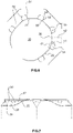
- FIG.3 shows that each of the clamping flanges (20) take the conical trunk shape of the upper portion (a) of the cans (A), have a smaller upper base (23) of a polygonal-elliptical shape corresponding to the perimeter contour (31) of each of the receiving openings (30) and have a larger lower base (24).
- the polygonal-elliptical cut line (32) that forms the receiving opening (30) has an interrupted section (33) located adjacent to the upper central area (10) of the device, through which the covering flaps (60) are attached to the device.
- the receiving openings (30) have a larger diameter (34) arranged along their length and at least a smaller diameter (35) arranged along their width, where these openings (30) are oriented in the device (1) diagonally with their larger diameter (34) coinciding with an imaginary diagonal axis (11) rotated by 45° with respect to a longitudinal central axis (12) and a transverse central axis (13), and where the openings (30) are distributed equidistant and symmetrical with respect to these axes.
- the two types of retainer fins (50) are made up of a plurality of radially symmetrical and spaced pairs of cuts (51), each consisting of a straight distal portion (52) with one end (53) coinciding with the perimeter contour (31) of the opening (30), and a curved opposite end (54) proximally, where the curved ends (54) of both cuts (51) of each pair of cuts are opposite each other; while the two radial cuts (51) are spaced each other by a distance (d1) which is less than a greater distance (d2) between each pair of cuts and because the distance (d1) between the two cuts (51) of each pair forms an auxiliary flange (55); while the greater distance (d2) of separation between the auxiliary flanges (55) form trapezoidal wings (56) intercalated with these auxiliary flanges (55) and where the radial height (h1) of the radial cuts (51) is preferably equivalent to half the width (h2) of the flange (20).
- the assembly of retaining fins (50) comprises two end fins (57), each located at each proximal ends (22) of the flange (20), where these end fins (57) lack the last radial cut (51) and have a curved shape extending from the bottom of the flange to the upper central area (10) of the device.
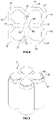
- the carrier device (1) comprises an outer contour (14) preferably formed by four sides (15) parallel in pairs, an upper side (16), a lower side (17) and beveled corners (18) where the four sides (15) of the contour are provided with at least one entering recess (19) arranged between the flanges (20), which coincides with the lower end (73) of the transition portions (70); while the upper substantially horizontal central area (10) comprises a central hinged hole (80) suitable for serving as a handle where the user inserts a finger and lifts the package of cans assembled by the device (1).
- This hole (80) consists of an incomplete circular cut (81) with one or more connecting bridges (82) which keep it weakly attached to the upper central area (10) of the device.
- the assembly formed by the clamping flange (20) with the receiving opening (30) and its corresponding covering flap (60) is at least two per device (1); whereas in a preferred embodiment shown in FIG. 9 , the assembly formed by the clamping flange (20) with the receiving opening (30) and its corresponding covering flap (60) is at least four per device (1).
- the carrier device (1) is made of a single laminar piece of biodegradable cellulosic material, where the cellulosic material is preferably a sheet weighing between 250 and 600 grams per square millimeter.
- the invention also includes the template (100) to conform to said carrier device (1) for grouping and transporting a set of beverage cans forming a package, where said template (100), as seen in FIG.10 , is made up of a flat plate comprising a contour (140) with four perimeter sides (150) parallel in pairs, each with a recess (190) centered on that side (150) and with beveled edges (180); a central area (101) from which arched portions (200) extend radially, the bases of which (201) pointing towards the central area (101) and each of which surrounding the corresponding receiving openings (300) of polygonal-elliptical shape (310) which are partially covered by a flap (600) also of polygonal-elliptical shape.
- These recesses (190) are centered on each of the sides (150) of the template and these beveled corners (180) can be smooth edged.
- this contour (310) of the openings (300) comprises a series of radial cuts (510) extending into the arc-shaped portions (200), which are grouped in pairs to form two different types of retainer fins (500); while intercalated between the arched portions (200) there are radial transition areas (700) of concave sides (710) extending from the central area (101) to each of the recesses (190) of the perimeter sides (150) of the template.
- the central area (101) includes an incomplete circular cut (801) that marks a circular piece (800) that can be folded, while the receiving openings (300) and these covering flaps (600) are generated by a cut line (320) with a polygonal-elliptical path that has an interrupted section (330) located adjacent to the central area (101) through which the covering flaps (600) are joined to the template (100).
- the recesses (190) which are centered on each of the sides (150) of the template and these beveled corners (180) comprise a notch (900) which facilitates the handling and positioning of the template on an installation machine during its assembly on the cans.
- the radial cuts (510) forming the retainer fins (500) each consist of a straight distal portion (520) with one end (530) coinciding with the perimeter contour (310) of the opening (300), and an opposite end (540) curved, where these curved ends (540) of both radial cuts (510) of each pair of cuts are facing each other.
- the pairs of radial cuts (510) are distributed over an outer portion of these arched portions (200) which is approximately three-quarters of the length of the largest diameter (340) of these polygonal-elliptical openings (300).
- the polygonal-elliptical shaped openings (300), their surrounding arched portions (200) and the covering flaps (600) are two per template (100) to carry two cans or may be six, to make a package of six cans, as shown in FIG. 13 .
- this alternative template for six cans there are two central areas (101), each comprising an incomplete circular cut (801) demarcating a circular piece (800) that can be folded.
- the receiving openings (300) and these covering flaps (600) are also generated by a polygonal-elliptical cut line (320) with an interrupted section (330) located adjacent to the central area (101) through which the covering flaps (600) are joined to the template (100).
- the template (100) is made of a single laminated piece of 100% biodegradable and recyclable cellulose material, which is preferably a sheet weighing between 250 and 600 grams per square millimeter.
- the templates can be manufactured in arrays of several templates that facilitate the handling of the assembly and its simultaneous installation on a larger number of cans, especially in an automated assembly system; where the templates are joined together by weakened junction points that break when pressure is applied to the template arrangement, causing them to separate and each to be installed on a corresponding group of cans, resulting in an individual pack of two, four, six or more cans.
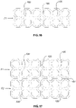
- the template (100) for carrying four cans can be arranged in a single-row linear arrangement (F1) comprising at least three templates (100) joined by opposite sides (150) of the template.
- the same template (100) is arranged in an arrangement comprising six templates (100) arranged in two rows (F1, F2) of three templates (100) each, where the templates in the same row (F1) are joined to each other by opposite sides (150), while the templates (100) in a row (F1) are joined to the attached row (F2) by a common side (151).
- the template (100) for carrying six cans can be arranged in a single-row linear arrangement (F1) comprising two templates (100) joined by opposite sides (150) of the template.
- the same template (100) is arranged in an arrangement comprising six templates (100) arranged in two rows (F1, F2) of two templates (100) each, where the templates in the same row (F1) are joined to each other by opposite sides (150), while the templates (100) in a row (F1) are joined to the attached row (F2) by a common side (151).
Landscapes
- Engineering & Computer Science (AREA)
- Mechanical Engineering (AREA)
- Packages (AREA)
- Buffer Packaging (AREA)
Applications Claiming Priority (1)
| Application Number | Priority Date | Filing Date | Title |
|---|---|---|---|
| PCT/CL2020/050018 WO2021179099A1 (es) | 2020-03-13 | 2020-03-13 | Dispositivo portador para agrupar y transportar un conjunto de latas de bebestibles |
Publications (2)
| Publication Number | Publication Date |
|---|---|
| EP4119465A1 true EP4119465A1 (de) | 2023-01-18 |
| EP4119465A4 EP4119465A4 (de) | 2023-11-15 |
Family
ID=77671090
Family Applications (1)
| Application Number | Title | Priority Date | Filing Date |
|---|---|---|---|
| EP20924941.6A Pending EP4119465A4 (de) | 2020-03-13 | 2020-03-13 | Trägervorrichtung zum gruppieren und transportieren eines satzes von getränkedosen |
Country Status (12)
| Country | Link |
|---|---|
| US (1) | US12110162B2 (de) |
| EP (1) | EP4119465A4 (de) |
| JP (1) | JP7459282B2 (de) |
| KR (1) | KR20220149785A (de) |
| CN (1) | CN115427316B (de) |
| AR (1) | AR121563A1 (de) |
| AU (1) | AU2020435468A1 (de) |
| CO (1) | CO2022012978A2 (de) |
| GB (1) | GB2608065B (de) |
| MX (1) | MX2022011317A (de) |
| WO (1) | WO2021179099A1 (de) |
| ZA (1) | ZA202210410B (de) |
Cited By (4)
| Publication number | Priority date | Publication date | Assignee | Title |
|---|---|---|---|---|
| WO2024220808A1 (en) * | 2023-04-19 | 2024-10-24 | Illinois Tool Works Inc. | Feed system for container carrier applicating machine |
| DE102023120529A1 (de) * | 2023-08-02 | 2025-02-06 | Krones Aktiengesellschaft | Verpackungsvorrichtung zum Anbringen eines Verpackungszuschnitts an eine Artikelzusammenstellung, Verpackungszuschnitt, Verpackungseinheit und Verfahren zum Herstellen einer Verpackungseinheit |
| US12522412B2 (en) | 2023-04-19 | 2026-01-13 | Illinois Tool Works Inc. | Container carrier |
| US12534244B2 (en) | 2023-04-19 | 2026-01-27 | Illinois Tool Works Inc. | Feed system for container carrier applicating machine |
Families Citing this family (4)
| Publication number | Priority date | Publication date | Assignee | Title |
|---|---|---|---|---|
| USD944655S1 (en) * | 2019-11-29 | 2022-03-01 | Jirasak Rattanapaibooncharoen | Double cup carrier |
| DE102021129507A1 (de) | 2021-11-12 | 2023-05-17 | Krones Aktiengesellschaft | Multipack und Verfahren zum Herstellen eines Multipacks |
| EP4588813A1 (de) | 2022-09-13 | 2025-07-23 | Herrera Muñoz, Jorge Fundador | Applikatorsystem zum ankoppeln mindestens eines trägers an einen satz von getränkedosen zur bildung einer oder mehrerer verpackungen |
| WO2025151497A1 (en) * | 2024-01-09 | 2025-07-17 | Graphic Packaging International, Llc | Carrier for containers |
Family Cites Families (29)
| Publication number | Priority date | Publication date | Assignee | Title |
|---|---|---|---|---|
| US3374028A (en) * | 1967-04-27 | 1968-03-19 | Illinois Tool Works | Container carrier |
| US3721337A (en) * | 1971-02-19 | 1973-03-20 | Illinois Tool Works | Quick opening container package |
| US3733100A (en) * | 1971-05-05 | 1973-05-15 | Illinois Tool Works | Container carrier stock |
| GB1340792A (en) * | 1972-11-30 | 1974-01-30 | Bowater Packaging Ltd | Packaging device |
| GB1479729A (en) * | 1974-10-16 | 1977-07-13 | Robinson Multiple Packaging Lt | Packaging cans |
| US4033457A (en) * | 1975-01-17 | 1977-07-05 | Illinois Tool Works Inc. | Reel-windable container carrier stock |
| GB1604840A (en) | 1978-05-31 | 1981-12-16 | Joyce M F | Carriers for containers apparatus and method for applying same to containers |
| US4546876A (en) * | 1983-09-09 | 1985-10-15 | Owens-Illinois, Inc. | Bottle carrier |
| SE8903443L (sv) * | 1989-10-19 | 1991-04-20 | Haakan Edqvist | Baerare foer samlingspaketering av burkfoerpackningar |
| US4974726A (en) * | 1990-05-07 | 1990-12-04 | Illinois Tool Works, Inc. | Clip-on sheet for beverage cans and package using same |
| US5193673A (en) | 1991-04-12 | 1993-03-16 | Thomas Rathbone | Environmentally safe holder device |
| US5246113A (en) | 1992-02-11 | 1993-09-21 | Riverwood International Corporation | Carrier for stacked articles |
| NZ248777A (en) | 1992-10-27 | 1995-07-26 | Mead Corp | Package for beverage cans has a divider within a carton to arrange the beverage cans into two vertically aligned tiers |
| US5305877A (en) | 1993-04-21 | 1994-04-26 | Illinois Tool Works Inc. | Carrier stock with outer band segments having concave edge portions |
| AU665151B2 (en) * | 1993-08-19 | 1995-12-14 | Illinois Tool Works Inc. | Container package with composite carrier |
| US5503267A (en) | 1995-04-11 | 1996-04-02 | Riverwood International Corporation | Can clip carrier with glue flaps |
| US5944174A (en) * | 1998-01-14 | 1999-08-31 | Illinois Tool Works, Inc. | Top grip container clip |
| ES2159235B1 (es) | 1999-05-11 | 2002-04-01 | Servicio Tecnico Del Embalaje | Embalaje para envases |
| SE522020C2 (sv) * | 2001-07-03 | 2004-01-07 | Smurfit Munksjoe Packaging Ab | Bärbar hållare av papp |
| JP5474099B2 (ja) * | 2009-02-24 | 2014-04-16 | グラフィック パッケージング インターナショナル インコーポレイテッド | 容器用パッケージ |
| GB201019848D0 (en) * | 2010-11-23 | 2011-01-05 | Dijofi Ltd | A machine and system for applying container carriers to containers |
| US20180362234A1 (en) | 2014-01-07 | 2018-12-20 | Fishbone Packaging, Inc. | Container carrying device |
| GB201411919D0 (en) * | 2014-07-03 | 2014-08-20 | British Polythene Ltd | A container carrier |
| EP4417536A3 (de) * | 2016-05-02 | 2025-04-16 | WestRock Packaging Systems, LLC | Zuschnitt zur herstellung eines artikelträgers |
| CA2984682A1 (en) * | 2017-02-03 | 2018-08-03 | Westrock Packaging Systems, Llc | Carton and blank therefor |
| EP3577036A1 (de) * | 2017-02-03 | 2019-12-11 | WestRock Packaging Systems, LLC | Karton und zuschnitt dafür |
| ES1208411Y (es) | 2018-02-22 | 2018-06-21 | Ferres Josep Maria Berga | Dispositivo portador de latas de bebidas |
| WO2021211998A1 (en) * | 2020-04-17 | 2021-10-21 | Westrock Packaging Systems, Llc | Packages, article carriers and blanks therfor |
| US11623804B2 (en) * | 2020-10-26 | 2023-04-11 | Illinois Tool Works Inc. | Container carrier with apertures |
-
2020
- 2020-03-13 US US17/910,659 patent/US12110162B2/en active Active
- 2020-03-13 EP EP20924941.6A patent/EP4119465A4/de active Pending
- 2020-03-13 GB GB2213389.6A patent/GB2608065B/en active Active
- 2020-03-13 KR KR1020227035325A patent/KR20220149785A/ko active Pending
- 2020-03-13 JP JP2022555097A patent/JP7459282B2/ja active Active
- 2020-03-13 MX MX2022011317A patent/MX2022011317A/es unknown
- 2020-03-13 AU AU2020435468A patent/AU2020435468A1/en active Pending
- 2020-03-13 WO PCT/CL2020/050018 patent/WO2021179099A1/es not_active Ceased
- 2020-03-13 CN CN202080099951.2A patent/CN115427316B/zh active Active
-
2021
- 2021-03-12 AR ARP210100636A patent/AR121563A1/es active IP Right Grant
-
2022
- 2022-09-13 CO CONC2022/0012978A patent/CO2022012978A2/es unknown
- 2022-09-20 ZA ZA2022/10410A patent/ZA202210410B/en unknown
Cited By (5)
| Publication number | Priority date | Publication date | Assignee | Title |
|---|---|---|---|---|
| WO2024220808A1 (en) * | 2023-04-19 | 2024-10-24 | Illinois Tool Works Inc. | Feed system for container carrier applicating machine |
| US12522412B2 (en) | 2023-04-19 | 2026-01-13 | Illinois Tool Works Inc. | Container carrier |
| US12534244B2 (en) | 2023-04-19 | 2026-01-27 | Illinois Tool Works Inc. | Feed system for container carrier applicating machine |
| DE102023120529A1 (de) * | 2023-08-02 | 2025-02-06 | Krones Aktiengesellschaft | Verpackungsvorrichtung zum Anbringen eines Verpackungszuschnitts an eine Artikelzusammenstellung, Verpackungszuschnitt, Verpackungseinheit und Verfahren zum Herstellen einer Verpackungseinheit |
| WO2025026658A1 (de) * | 2023-08-02 | 2025-02-06 | Krones Aktiengesellschaft | Verpackungsvorrichtung zum anbringen eines verpackungszuschnitts an eine artikelzusammenstellung, verpackungszuschnitt, verpackungseinheit und verfahren zum herstellen einer verpackungseinheit |
Also Published As
| Publication number | Publication date |
|---|---|
| GB2608065A (en) | 2022-12-21 |
| AU2020435468A1 (en) | 2022-10-06 |
| CN115427316A (zh) | 2022-12-02 |
| CO2022012978A2 (es) | 2022-12-09 |
| WO2021179099A1 (es) | 2021-09-16 |
| US20230134359A1 (en) | 2023-05-04 |
| GB2608065B (en) | 2024-04-24 |
| AR121563A1 (es) | 2022-06-15 |
| MX2022011317A (es) | 2022-11-14 |
| KR20220149785A (ko) | 2022-11-08 |
| JP2023526154A (ja) | 2023-06-21 |
| ZA202210410B (en) | 2024-01-31 |
| EP4119465A4 (de) | 2023-11-15 |
| CN115427316B (zh) | 2026-04-14 |
| GB202213389D0 (en) | 2022-10-26 |
| JP7459282B2 (ja) | 2024-04-01 |
| CA3164762A1 (en) | 2021-09-16 |
| BR112022012932A2 (pt) | 2022-09-20 |
| US12110162B2 (en) | 2024-10-08 |
Similar Documents
| Publication | Publication Date | Title |
|---|---|---|
| US12110162B2 (en) | Carrier device for grouping and transporting a set of beverage cans | |
| EP3792193B1 (de) | Obergriffträger für getränkedose und anordnung | |
| EP1077183B1 (de) | Behälterträger | |
| US5230425A (en) | Carrier for bunch packaging of cans | |
| CN116323421A (zh) | 用于容器的载体 | |
| US3997057A (en) | Stacking means for packing tray | |
| US6874620B2 (en) | Container carrier | |
| FI97047B (fi) | Kädensijalla varustettu käärintäkantokotelo | |
| JPH11502180A (ja) | 積み重ねたびんのためのキャリヤー | |
| GB2168325A (en) | Reusable wrap-type multi-pack carrier | |
| US4915217A (en) | Container package | |
| CA3164762C (en) | Carrier device for grouping and transporting a set of beverage cans | |
| US20060283744A1 (en) | Multipack and blank and apparatus for the manufacture thereof | |
| MXPA06012530A (es) | Portador divisible para envases. | |
| CA2050008C (en) | Beverage container carrier | |
| US20070215682A1 (en) | Carton having handling-facilitating apertures | |
| RU2805096C1 (ru) | Несущее устройство для группировки и транспортировки набора банок для напитков | |
| JP2025504996A (ja) | 物品キャリア及びそのためのブランク | |
| JP7367025B2 (ja) | 容器用キャリア | |
| MXPA04007587A (es) | Caja de carton y preforma de carton. | |
| KR102104184B1 (ko) | 운반 손잡이를 갖는 패키지 및 블랭크 | |
| EP0453240B1 (de) | Abdeckkarton für Flaschenkasten | |
| EP4711303A1 (de) | Mehrstück-flaschenträger | |
| BR112022012932B1 (pt) | Dispositivo carregador para agrupamento e transporte de um conjunto de latas de bebidas e molde para formar um dispositivo carregador | |
| WO2002081323A1 (en) | Carrier for bottles |
Legal Events
| Date | Code | Title | Description |
|---|---|---|---|
| STAA | Information on the status of an ep patent application or granted ep patent |
Free format text: STATUS: THE INTERNATIONAL PUBLICATION HAS BEEN MADE |
|
| PUAI | Public reference made under article 153(3) epc to a published international application that has entered the european phase |
Free format text: ORIGINAL CODE: 0009012 |
|
| STAA | Information on the status of an ep patent application or granted ep patent |
Free format text: STATUS: REQUEST FOR EXAMINATION WAS MADE |
|
| 17P | Request for examination filed |
Effective date: 20220704 |
|
| AK | Designated contracting states |
Kind code of ref document: A1 Designated state(s): AL AT BE BG CH CY CZ DE DK EE ES FI FR GB GR HR HU IE IS IT LI LT LU LV MC MK MT NL NO PL PT RO RS SE SI SK SM TR |
|
| DAV | Request for validation of the european patent (deleted) | ||
| DAX | Request for extension of the european patent (deleted) | ||
| A4 | Supplementary search report drawn up and despatched |
Effective date: 20231017 |
|
| RIC1 | Information provided on ipc code assigned before grant |
Ipc: B65D 71/50 20060101ALI20231011BHEP Ipc: B65D 17/40 20060101ALI20231011BHEP Ipc: B65B 17/02 20060101ALI20231011BHEP Ipc: B65D 71/42 20060101AFI20231011BHEP |
|
| STAA | Information on the status of an ep patent application or granted ep patent |
Free format text: STATUS: EXAMINATION IS IN PROGRESS |
|
| 17Q | First examination report despatched |
Effective date: 20260311 |