EP4119469A1 - Dispositif de levage et de pivotement - Google Patents
Dispositif de levage et de pivotement Download PDFInfo
- Publication number
- EP4119469A1 EP4119469A1 EP22183325.4A EP22183325A EP4119469A1 EP 4119469 A1 EP4119469 A1 EP 4119469A1 EP 22183325 A EP22183325 A EP 22183325A EP 4119469 A1 EP4119469 A1 EP 4119469A1
- Authority
- EP
- European Patent Office
- Prior art keywords
- clamp
- lifting
- clamping section
- section
- support
- Prior art date
- Legal status (The legal status is an assumption and is not a legal conclusion. Google has not performed a legal analysis and makes no representation as to the accuracy of the status listed.)
- Granted
Links
Images



Classifications
-
- B—PERFORMING OPERATIONS; TRANSPORTING
- B66—HOISTING; LIFTING; HAULING
- B66F—HOISTING, LIFTING, HAULING OR PUSHING, NOT OTHERWISE PROVIDED FOR, e.g. DEVICES WHICH APPLY A LIFTING OR PUSHING FORCE DIRECTLY TO THE SURFACE OF A LOAD
- B66F9/00—Devices for lifting or lowering bulky or heavy goods for loading or unloading purposes
- B66F9/06—Devices for lifting or lowering bulky or heavy goods for loading or unloading purposes movable, with their loads, on wheels or the like, e.g. fork-lift trucks
- B66F9/075—Constructional features or details
- B66F9/12—Platforms; Forks; Other load supporting or gripping members
- B66F9/19—Additional means for facilitating unloading
-
- B—PERFORMING OPERATIONS; TRANSPORTING
- B65—CONVEYING; PACKING; STORING; HANDLING THIN OR FILAMENTARY MATERIAL
- B65F—GATHERING OR REMOVAL OF DOMESTIC OR LIKE REFUSE
- B65F3/00—Vehicles particularly adapted for collecting refuse
- B65F3/02—Vehicles particularly adapted for collecting refuse with means for discharging refuse receptacles thereinto
- B65F3/04—Linkages, pivoted arms, or pivoted carriers for raising and subsequently tipping receptacles
- B65F3/041—Pivoted arms or pivoted carriers
-
- B—PERFORMING OPERATIONS; TRANSPORTING
- B65—CONVEYING; PACKING; STORING; HANDLING THIN OR FILAMENTARY MATERIAL
- B65F—GATHERING OR REMOVAL OF DOMESTIC OR LIKE REFUSE
- B65F3/00—Vehicles particularly adapted for collecting refuse
- B65F3/02—Vehicles particularly adapted for collecting refuse with means for discharging refuse receptacles thereinto
- B65F2003/0223—Vehicles particularly adapted for collecting refuse with means for discharging refuse receptacles thereinto the discharging means comprising elements for holding the receptacle
- B65F2003/024—Means for locking the rim
-
- B—PERFORMING OPERATIONS; TRANSPORTING
- B65—CONVEYING; PACKING; STORING; HANDLING THIN OR FILAMENTARY MATERIAL
- B65F—GATHERING OR REMOVAL OF DOMESTIC OR LIKE REFUSE
- B65F3/00—Vehicles particularly adapted for collecting refuse
- B65F3/02—Vehicles particularly adapted for collecting refuse with means for discharging refuse receptacles thereinto
- B65F2003/0263—Constructional features relating to discharging means
Definitions
- the invention relates to a lifting and tipping device with the features of claim 1.
- a lifting and tipping device with a receptacle for refuse containers arranged on a swivel arm.
- This has a receiving comb with an associated terminal strip and a barrel stop, both the receiving comb and the barrel stop having foldable end parts at the lateral ends.
- the device can be used in particular for so-called side loaders.
- the foldable end parts are folded to the side and only the central section of the receiver accommodates the refuse container. If four-wheeled refuse containers are to be emptied, the end parts are folded forward so that a continuous receptacle is formed, which corresponds to the larger width of the four-wheeled refuse containers.
- the clamping strip In the operating position for four-wheeled refuse containers, the clamping strip only overlaps the central area of the receiving comb. This does not comply with the DIN EN1501-5 standard, which for safety reasons requires 90% overlap of the comb with the locking strip. Too little clamping action can cause the bin to fall, endangering the operator.
- the apron which is usually attached to the terminal strip, is missing in the lateral areas, which prevents the recyclable material from being lost when the waste container is emptied into the collector.
- the device is relatively wide in the state with the side parts folded backwards because of the barrel supports protruding to the side. The lifting and tipping device is switched on to grab refuse containers that are standing at a distance from the roadside moves with an extendable arm. However, especially in urban areas with many parked cars, it is advantageous if the device is as narrow as possible.
- the invention relates to a lifting and tipping device, in particular for a garbage truck, with a swivel arm and a holder for garbage containers arranged thereon, the holder having a middle part with a central comb and a middle clamp for securely holding a garbage container and a bin support, the holder at least has a side part with a clamping section with a side comb and a side clamp for captively holding a refuse container and a support section with a bin support, the clamping section and the support section being articulated to the middle part, so that the at least one side part can be moved from an unfolded position in which it expands the central part to accommodate wider refuse containers, can be brought into a folded position.
- the lift-tilt device can be used to lift and empty both two-wheel and wider four-wheel bins. Only the center section is used for use with two-wheel bins. The at least one side part is folded back, the device is in a folded position. The bin is picked up by the teeth of the center comb which engage corresponding pockets in the bin. At a predetermined point in time, such as when a certain height is reached during the lifting process, the middle clamp is moved and the waste container is captively held between the middle comb and the middle clamp. The waste container is supported with the barrel support.
- the at least one side part is folded forward so that its side comb and side clamp with the middle comb and middle clamp form a continuous comb with the clamp. This is referred to as the unfolded position. This ensures that the waste container is held across the entire width between the receiving comb and the clamping strip, which guarantees the safety of the operating personnel in accordance with the standard.
- the bin support is widened so that the waste container is also supported over its entire width.
- the at least one side part is divided into two components, the clamping section and the support section, which are each articulated to the middle part.
- This offers the possibility of folding the two components independently of one another and thus making optimal use of the available installation space.
- the clamping section is pivoted essentially through 90° to the rear and the supporting section is essentially pivoted through 180° to the rear.
- the barrel support of the support section which projects further, does not contribute to the width of the lifting and tipping device in the folded position.
- the barrel support comes to rest on the back of the swivel arm. This results in a minimum width of the device that is not significantly wider than the center crest. This improves the possible uses, especially in confined spaces.
- the joint axis of the clamping section and the joint axis of the support section are inclined relative to one another. Since the joint axes do not coincide, the pivoting movements of the clamping section and the support section are independent of one another, so that the width-optimized configuration in particular is supported as a result.
- the articulation axis of the clamping section is aligned essentially parallel to the vertical direction of the vehicle and the articulation axis of the support section is inclined relative thereto away from the refuse vehicle.
- the middle clamp and the at least one side clamp are positively connected to one another. This means that only the middle clamp has to be driven, which also moves the side clamp via the form fit in order to clamp the refuse container. This leads to a simplification of the device, since additional drives are saved, which is beneficial to the installation space and the complexity of the control.
- the middle clamp and the at least one side clamp are positively connected via a pin which is arranged on the side clamp and which engages in a corresponding recess in the middle clamp.
- the recess is designed in such a way that the pin slides into the recess during the folding movement.
- the recess can be designed, for example, as a slot in the terminal strip.
- a further advantageous embodiment of the invention provides that a first open profile is arranged on the clamping section and a second open profile is arranged on the support section, with the ends of the profiles facing one another being beveled and in the unfolded position the second profile overlaps the first profile, to form a form fit.
- a garbage container rests on the bin support of the support section, it exerts a force on it.
- the form fit makes it possible to transmit the high forces exerted by the loaded refuse containers and also to support them via the clamping section.
- the first profile and the second profile interlock during the folding movement.
- the beveled free ends of the profiles allow the profiles to move freely, since the clamping section and the supporting section move about different joint axes.
- At least one guide element is arranged on the clamping section, in which a push rod is guided, which is guided at its lower end via an articulated connection on a slide rail, which is arranged on the support section.
- This construction makes it possible to drive only the clamping section for the folding movement. Its movement is transmitted to the support section via the push rod. This saves installation space and reduces the complexity of the device. Controlling the device is also simplified. Since the joint axes of the clamping section and supporting section do not run parallel or collinear and, in addition, the clamping section pivots by essentially 90° in an advantageous embodiment, while the supporting section preferably pivots by essentially 180°, it is necessary to limit the movement of the clamping section in a suitable manner to translate. This is achieved in particular by the movable connection point of the push rod on the support section.
- the articulated connection of the push rod to the slide rail enables the push rod to be moved in all three spatial directions, as would be possible with a ball joint, for example.
- the lower end of the push rod with the articulated connection slides along the slide rail.
- the at least one guide element for the push rod is preferably arranged in the first profile of the clamping section.
- an actuator is provided which is set up to pivot the at least one side part from the folded position into the unfolded position and back. This makes it possible to switch the device into both positions, preferably by remote control, as soon as a change from four-wheel to two-wheel garbage containers takes place, which is accompanied by a considerable reduction in the workload for the operating personnel.
- This is preferably a pneumatically or hydraulically operated cylinder actuator that is easy to maintain and to control.
- the actuator is preferably in operative connection with the clamping section of the at least one side part. Especially when the clamping section is connected to the support section, preferably as described above, only one actuator has to be provided for the folding movement of the entire side part, since the support section is carried along with the movement of the clamping section. This makes control easier and saves installation space and weight.
- two side parts are preferably provided in one embodiment of the invention and the actuator is operatively connected to the side parts in a floating manner.
- Floating is to be understood as meaning that the actuator is only connected to the side parts and not additionally, for example, to the central part in order to be supported there.
- this bearing means that the side parts do not fold out synchronously, it has the advantage that both side parts or both clamping sections and support sections can be moved with a single actuator.
- the actuator is arranged below the center ridge on its side facing away from the vehicle.
- the actuator is preferably connected to the side part or the clamping section in an articulated manner.
- the connection points are preferably located in the area of the joint between the central part and the side part or the clamping section.
- a lifting and tipping device 1 with a swivel arm 2 and a receptacle 3 arranged thereon for refuse containers is shown.
- Such a lifting and tipping device 1 is usually arranged on a collection container of a garbage truck. It is used to lift a refuse container and into the collection container to empty, with the garbage container is pivoted overhead. For this it is necessary that the refuse container is captively held in the receptacle 3 .
- the receptacle 3 has a middle part 4 with a middle comb 5 and a middle clamp 6 .
- a bin support 7 is provided below the middle comb 5 and middle clamp 6 to support the refuse container.
- Right and left of the middle part 4 is a side part 8.9 articulated. Since the two side parts 8, 9 are each designed symmetrically, reference numbers have been omitted on one side for the sake of clarity.
- the side parts 8, 9 are divided in two and consist of a clamping section 10 with a side comb 11 and a side clamp 12.
- the clamping section 10 is connected to the central part 4 in an articulated manner via a first joint 13.
- the support section 14 is connected in an articulated manner to the central part 4 via a second joint 15 .
- the second joint 15 is in figure 1 covered by the tons of pads 7.16 of the middle part 4 and support section 14. In the rear view in 4 or in the perspective view in 7 it's better to see
- the lifting and tipping device 1 is shown in an unfolded position.
- the central ridge 5 forms a continuous ridge with the side ridges 11, which can accommodate a wide four-wheel garbage container with a volume of up to 1100 liters.
- the teeth of the comb dip into corresponding pockets in the waste container.
- the waste container is clamped and held captive by the continuous clamp, which is formed from the middle clamp 6 and the side clamps 12 .
- 1 shows the terminals 6, 12 in the closed state, which is in the sectional view of 2 can be seen clearly.
- the continuous clamp extends over the entire width of the wide comb, so that increased loss security is guaranteed in accordance with standard specifications.
- a continuous apron 31 ensures that no waste can be lost even when emptying a wide waste container.
- the bin supports 7.16 of the middle part 4 and side parts 8.9 form a continuous ton support that can support a four-wheeled garbage container over its entire width.
- the middle clamp 6 is actuated by a clamp actuator 17 (see 4 , 8th , 9 ) emotional. It transmits this movement to the side clamps 12 via a pin 18 which is arranged on the side clamps 12 ( 6 , 7 ) and which engages in a recess 19, so that the middle clamp 6 and the side clamps 12 are positively connected to one another. It is therefore not necessary for the side clamps 12 to be provided with a separate drive.
- the side panels 8.9 are folded back. This process is based on the illustrations in the Figures 5 to 7 shown.
- An actuator 20 is arranged below the central comb 5 and is designed here as a cylinder actuator.
- the actuator 20 is in operative connection with the clamping sections 10 of the side parts 8,9. This means that the actuator 20 acts on the clamping sections 10 and moves them. In this case, however, the actuator 20 is not connected to the central part 4 and is therefore not supported on it.
- This floating storage means that the side panels 8.9 are not folded synchronously. However, the central part 4 is not unnecessarily burdened with it.
- the connection points 21,22 of the actuator 20 are located adjacent to the first joints 13 between the central part 4 and the clamping section 10 of the side parts 8,9.
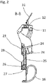
- a first open profile 23 is arranged on the clamping section 10 .
- Two guide elements 24 are arranged therein, in which a push rod 25 is guided.
- the push rod 25 is guided via an articulated connection 26 on a slide rail.
- a second open profile 28 is arranged on the support section 14 .
- the second open profile 28 overlaps the first open profile 23, so that the profile forms a form fit with respect to a force emanating from the drum support 16 (see Fig 8 ).
- the force that a filled refuse container exerts on the support section 14 is diverted.
- the ends of the profiles 23, 28 facing one another are beveled so that they can be positioned one above the other without any problems during the folding movement.
- the side parts 8.9 are no longer necessary and are being replaced folded at the back.
- the clamping sections 10 of the side parts 8.9 are moved by the actuator 20. This is done remotely from the driver's cab. The movement is transmitted to the support section 14 via the push rod 25 .
- the connection point of the push rod 25 slides along the slide rail 27.
- the articulated connection 26 between the push rod 25 and the slide rail 26 enables the push rod 25 to rotate in all three spatial directions in the manner of a ball joint.
- the joint axes 29, 30 of the first joint 13 of the clamping section 10 and of the second joint 15 of the support section 14 are not parallel or collinear, but inclined towards one another.
- the joint axis 29 of the first joint 13 of the clamping section 10 is essentially aligned in the vertical direction of the vehicle.
- the joint axis 30 of the second joint 15 of the support section 14 is inclined relative thereto away from the garbage truck. This means that the folding movement of the two sections 10,14 is independent of one another.
- the support sections 14 are folded completely behind the middle part 4, so that the width of the lifting and tipping device 1 in the folded position is essentially determined by the width of the middle comb 5 and middle clamp 6. In this position, the lifting and tipping device 1 is used in transfer journeys close to the garbage truck and also takes up only minimal space.
- the reverse movement from the folded-in to the unfolded position is identical, only with the inverse direction of rotation.
- the actuator 20 in turn moves the clamping sections 10. This movement is transmitted to the respective support section 14 via the push rod 25.
- FIG. The pin 18 arranged on the side clamp 12 thereby engages in the recess 19 which is formed in the middle clamp 6 .
- the recess 19 is a slot in into which the pin 18 slides.
- a form-fitting connection is thereby formed, which enables the clamping movement of the middle clamp 6 to be transferred to the side clamp 12 .
- the continuous clamp formed from the middle clamp 6 and the side clamp 12 is advantageously driven by only a single clamp actuator 17 .
- the pivoting movement of the clamping section 10 and the support section 14 also causes the first open profile 23 and the second open profile 28 to come into contact, so that the second profile 28 overlaps the first profile 23 .
Landscapes
- Engineering & Computer Science (AREA)
- Transportation (AREA)
- Structural Engineering (AREA)
- Mechanical Engineering (AREA)
- Civil Engineering (AREA)
- Life Sciences & Earth Sciences (AREA)
- Geology (AREA)
- Refuse-Collection Vehicles (AREA)
Applications Claiming Priority (1)
| Application Number | Priority Date | Filing Date | Title |
|---|---|---|---|
| DE102021117999.8A DE102021117999B3 (de) | 2021-07-13 | 2021-07-13 | Hub-Kipp-Vorrichtung |
Publications (3)
| Publication Number | Publication Date |
|---|---|
| EP4119469A1 true EP4119469A1 (fr) | 2023-01-18 |
| EP4119469C0 EP4119469C0 (fr) | 2024-01-17 |
| EP4119469B1 EP4119469B1 (fr) | 2024-01-17 |
Family
ID=82399364
Family Applications (1)
| Application Number | Title | Priority Date | Filing Date |
|---|---|---|---|
| EP22183325.4A Active EP4119469B1 (fr) | 2021-07-13 | 2022-07-06 | Dispositif de levage et de pivotement |
Country Status (4)
| Country | Link |
|---|---|
| EP (1) | EP4119469B1 (fr) |
| DE (1) | DE102021117999B3 (fr) |
| ES (1) | ES2973800T3 (fr) |
| PL (1) | PL4119469T3 (fr) |
Families Citing this family (1)
| Publication number | Priority date | Publication date | Assignee | Title |
|---|---|---|---|---|
| DE102021133817B4 (de) | 2021-12-20 | 2024-02-01 | Ab Närpes Trä & Metall | Hub-Kippvorrichtung zur Aufnahme von Abfallbehältern |
Citations (2)
| Publication number | Priority date | Publication date | Assignee | Title |
|---|---|---|---|---|
| DE102004049463A1 (de) | 2003-12-09 | 2005-07-07 | Faun Umwelttechnik Gmbh & Co. Kg | Hub-Kippvorrichtung zur Aufnahme von Müllbehältern |
| EP3418219A1 (fr) * | 2017-06-23 | 2018-12-26 | Ab Närpes Trä & Metall - Oy Närpiön Puu ja Metalli | Dispositif de levage de poubelle |
-
2021
- 2021-07-13 DE DE102021117999.8A patent/DE102021117999B3/de active Active
-
2022
- 2022-07-06 ES ES22183325T patent/ES2973800T3/es active Active
- 2022-07-06 EP EP22183325.4A patent/EP4119469B1/fr active Active
- 2022-07-06 PL PL22183325.4T patent/PL4119469T3/pl unknown
Patent Citations (2)
| Publication number | Priority date | Publication date | Assignee | Title |
|---|---|---|---|---|
| DE102004049463A1 (de) | 2003-12-09 | 2005-07-07 | Faun Umwelttechnik Gmbh & Co. Kg | Hub-Kippvorrichtung zur Aufnahme von Müllbehältern |
| EP3418219A1 (fr) * | 2017-06-23 | 2018-12-26 | Ab Närpes Trä & Metall - Oy Närpiön Puu ja Metalli | Dispositif de levage de poubelle |
Also Published As
| Publication number | Publication date |
|---|---|
| DE102021117999B3 (de) | 2022-09-29 |
| PL4119469T3 (pl) | 2024-04-08 |
| ES2973800T3 (es) | 2024-06-24 |
| EP4119469C0 (fr) | 2024-01-17 |
| EP4119469B1 (fr) | 2024-01-17 |
Similar Documents
| Publication | Publication Date | Title |
|---|---|---|
| EP0173180B1 (fr) | Dispositif de basculement ou de soulèvement/basculement pour le vidage de récipients dans des récipients collecteurs, plus spécialement de poubelles dans le récipient collecteur d'un camion de voirie | |
| DE3620610C2 (de) | Greifervorrichtung für Müllbehälter | |
| EP0235784B1 (fr) | Dispositif de culbutage pour un véhicule à ordures | |
| DE2821295A1 (de) | Container-ladevorrichtung | |
| EP0399280B1 (fr) | Dispositif d'accouplement d'un moyen de levage à un conteneur | |
| EP0244732A2 (fr) | Véhicule pour la collecte d'ordures | |
| DE69615573T2 (de) | Holztransportvorrichtungen mit oberen querverbindungen | |
| DE102021117999B3 (de) | Hub-Kipp-Vorrichtung | |
| EP0143197B1 (fr) | Disposition pour actionner une benne preneuse | |
| DE4441551C1 (de) | Vorrichtung zum hängenden Anheben und Entleeren von Behältern, Containern od. dgl. | |
| DE2138674A1 (de) | Ladevorrichtung fuer lastfahrzeuge | |
| EP0564403A1 (fr) | Dispositif de chargement et de déchargement d'un porte-charges sur un véhicule | |
| EP0554528B1 (fr) | Dispositif de ramassage pour benne à ordures | |
| DE2632492A1 (de) | Behaeltertransportsystem | |
| DE19746401C2 (de) | Müllsammelfahrzeug mit seitlich angeordneter Hub-/Kippvorrichtung | |
| DE3114526A1 (de) | "foerderwagenkippgeraet" | |
| DE19952483C1 (de) | Verriegelungsvorrichtung für nebeneinander angeordnete Hubwagen | |
| DE3941348C2 (fr) | ||
| DE69801390T2 (de) | Hub-Kippvorrichtung für Behälter und mit einer solchen Vorrichtung ausgestatteter Müllsammelbehälter | |
| EP0006871B1 (fr) | Dispositif de levage et d'abaissement pour basculer une plateforme de chargement, notamment pour camions et remorques | |
| EP0819623B1 (fr) | Dispositif pour décharger des poubelles de grande dimension | |
| DE19831237C2 (de) | Vorrichtung zum Aufnehmen von Müllbehältern zur Verwendung bei Abfallsammelfahrzeugen | |
| DE1235800B (de) | Kippvorrichtung zum Entleeren von Behaeltern, insbesondere von Muellgefaessen in eine Einschuettvorrichtung | |
| DE10221371B4 (de) | Hubkippvorrichtung | |
| DE3527935A1 (de) | Ladevorrichtung fuer lastfahrzeugaufbauten |
Legal Events
| Date | Code | Title | Description |
|---|---|---|---|
| PUAI | Public reference made under article 153(3) epc to a published international application that has entered the european phase |
Free format text: ORIGINAL CODE: 0009012 |
|
| STAA | Information on the status of an ep patent application or granted ep patent |
Free format text: STATUS: THE APPLICATION HAS BEEN PUBLISHED |
|
| AK | Designated contracting states |
Kind code of ref document: A1 Designated state(s): AL AT BE BG CH CY CZ DE DK EE ES FI FR GB GR HR HU IE IS IT LI LT LU LV MC MK MT NL NO PL PT RO RS SE SI SK SM TR |
|
| STAA | Information on the status of an ep patent application or granted ep patent |
Free format text: STATUS: REQUEST FOR EXAMINATION WAS MADE |
|
| 17P | Request for examination filed |
Effective date: 20230222 |
|
| RBV | Designated contracting states (corrected) |
Designated state(s): AL AT BE BG CH CY CZ DE DK EE ES FI FR GB GR HR HU IE IS IT LI LT LU LV MC MK MT NL NO PL PT RO RS SE SI SK SM TR |
|
| P01 | Opt-out of the competence of the unified patent court (upc) registered |
Effective date: 20230602 |
|
| GRAP | Despatch of communication of intention to grant a patent |
Free format text: ORIGINAL CODE: EPIDOSNIGR1 |
|
| STAA | Information on the status of an ep patent application or granted ep patent |
Free format text: STATUS: GRANT OF PATENT IS INTENDED |
|
| INTG | Intention to grant announced |
Effective date: 20230824 |
|
| GRAS | Grant fee paid |
Free format text: ORIGINAL CODE: EPIDOSNIGR3 |
|
| GRAA | (expected) grant |
Free format text: ORIGINAL CODE: 0009210 |
|
| STAA | Information on the status of an ep patent application or granted ep patent |
Free format text: STATUS: THE PATENT HAS BEEN GRANTED |
|
| AK | Designated contracting states |
Kind code of ref document: B1 Designated state(s): AL AT BE BG CH CY CZ DE DK EE ES FI FR GB GR HR HU IE IS IT LI LT LU LV MC MK MT NL NO PL PT RO RS SE SI SK SM TR |
|
| REG | Reference to a national code |
Ref country code: GB Ref legal event code: FG4D Free format text: NOT ENGLISH |
|
| REG | Reference to a national code |
Ref country code: DE Ref legal event code: R096 Ref document number: 502022000397 Country of ref document: DE |
|
| REG | Reference to a national code |
Ref country code: CH Ref legal event code: EP |
|
| REG | Reference to a national code |
Ref country code: IE Ref legal event code: FG4D Free format text: LANGUAGE OF EP DOCUMENT: GERMAN |
|
| U01 | Request for unitary effect filed |
Effective date: 20240209 |
|
| U07 | Unitary effect registered |
Designated state(s): AT BE BG DE DK EE FI FR IT LT LU LV MT NL PT SE SI Effective date: 20240220 |
|
| P04 | Withdrawal of opt-out of the competence of the unified patent court (upc) registered |
Effective date: 20240216 |
|
| REG | Reference to a national code |
Ref country code: ES Ref legal event code: FG2A Ref document number: 2973800 Country of ref document: ES Kind code of ref document: T3 Effective date: 20240624 |
|
| PG25 | Lapsed in a contracting state [announced via postgrant information from national office to epo] |
Ref country code: IS Free format text: LAPSE BECAUSE OF FAILURE TO SUBMIT A TRANSLATION OF THE DESCRIPTION OR TO PAY THE FEE WITHIN THE PRESCRIBED TIME-LIMIT Effective date: 20240517 |
|
| PG25 | Lapsed in a contracting state [announced via postgrant information from national office to epo] |
Ref country code: GR Free format text: LAPSE BECAUSE OF FAILURE TO SUBMIT A TRANSLATION OF THE DESCRIPTION OR TO PAY THE FEE WITHIN THE PRESCRIBED TIME-LIMIT Effective date: 20240418 |
|
| PG25 | Lapsed in a contracting state [announced via postgrant information from national office to epo] |
Ref country code: HR Free format text: LAPSE BECAUSE OF FAILURE TO SUBMIT A TRANSLATION OF THE DESCRIPTION OR TO PAY THE FEE WITHIN THE PRESCRIBED TIME-LIMIT Effective date: 20240117 Ref country code: RS Free format text: LAPSE BECAUSE OF FAILURE TO SUBMIT A TRANSLATION OF THE DESCRIPTION OR TO PAY THE FEE WITHIN THE PRESCRIBED TIME-LIMIT Effective date: 20240417 |
|
| PG25 | Lapsed in a contracting state [announced via postgrant information from national office to epo] |
Ref country code: RS Free format text: LAPSE BECAUSE OF FAILURE TO SUBMIT A TRANSLATION OF THE DESCRIPTION OR TO PAY THE FEE WITHIN THE PRESCRIBED TIME-LIMIT Effective date: 20240417 Ref country code: NO Free format text: LAPSE BECAUSE OF FAILURE TO SUBMIT A TRANSLATION OF THE DESCRIPTION OR TO PAY THE FEE WITHIN THE PRESCRIBED TIME-LIMIT Effective date: 20240417 Ref country code: IS Free format text: LAPSE BECAUSE OF FAILURE TO SUBMIT A TRANSLATION OF THE DESCRIPTION OR TO PAY THE FEE WITHIN THE PRESCRIBED TIME-LIMIT Effective date: 20240517 Ref country code: HR Free format text: LAPSE BECAUSE OF FAILURE TO SUBMIT A TRANSLATION OF THE DESCRIPTION OR TO PAY THE FEE WITHIN THE PRESCRIBED TIME-LIMIT Effective date: 20240117 Ref country code: GR Free format text: LAPSE BECAUSE OF FAILURE TO SUBMIT A TRANSLATION OF THE DESCRIPTION OR TO PAY THE FEE WITHIN THE PRESCRIBED TIME-LIMIT Effective date: 20240418 |
|
| U20 | Renewal fee for the european patent with unitary effect paid |
Year of fee payment: 3 Effective date: 20240717 |
|
| PG25 | Lapsed in a contracting state [announced via postgrant information from national office to epo] |
Ref country code: SM Free format text: LAPSE BECAUSE OF FAILURE TO SUBMIT A TRANSLATION OF THE DESCRIPTION OR TO PAY THE FEE WITHIN THE PRESCRIBED TIME-LIMIT Effective date: 20240117 |
|
| REG | Reference to a national code |
Ref country code: DE Ref legal event code: R097 Ref document number: 502022000397 Country of ref document: DE |
|
| PG25 | Lapsed in a contracting state [announced via postgrant information from national office to epo] |
Ref country code: SK Free format text: LAPSE BECAUSE OF FAILURE TO SUBMIT A TRANSLATION OF THE DESCRIPTION OR TO PAY THE FEE WITHIN THE PRESCRIBED TIME-LIMIT Effective date: 20240117 |
|
| PG25 | Lapsed in a contracting state [announced via postgrant information from national office to epo] |
Ref country code: SM Free format text: LAPSE BECAUSE OF FAILURE TO SUBMIT A TRANSLATION OF THE DESCRIPTION OR TO PAY THE FEE WITHIN THE PRESCRIBED TIME-LIMIT Effective date: 20240117 Ref country code: SK Free format text: LAPSE BECAUSE OF FAILURE TO SUBMIT A TRANSLATION OF THE DESCRIPTION OR TO PAY THE FEE WITHIN THE PRESCRIBED TIME-LIMIT Effective date: 20240117 Ref country code: RO Free format text: LAPSE BECAUSE OF FAILURE TO SUBMIT A TRANSLATION OF THE DESCRIPTION OR TO PAY THE FEE WITHIN THE PRESCRIBED TIME-LIMIT Effective date: 20240117 |
|
| PLBE | No opposition filed within time limit |
Free format text: ORIGINAL CODE: 0009261 |
|
| STAA | Information on the status of an ep patent application or granted ep patent |
Free format text: STATUS: NO OPPOSITION FILED WITHIN TIME LIMIT |
|
| 26N | No opposition filed |
Effective date: 20241018 |
|
| P05 | Withdrawal of opt-out of the competence of the unified patent court (upc) changed |
Free format text: CASE NUMBER: APP_8422/2024 Effective date: 20240220 |
|
| PG25 | Lapsed in a contracting state [announced via postgrant information from national office to epo] |
Ref country code: MC Free format text: LAPSE BECAUSE OF FAILURE TO SUBMIT A TRANSLATION OF THE DESCRIPTION OR TO PAY THE FEE WITHIN THE PRESCRIBED TIME-LIMIT Effective date: 20240117 |
|
| PGFP | Annual fee paid to national office [announced via postgrant information from national office to epo] |
Ref country code: PL Payment date: 20250621 Year of fee payment: 4 |
|
| PGFP | Annual fee paid to national office [announced via postgrant information from national office to epo] |
Ref country code: CZ Payment date: 20250619 Year of fee payment: 4 |
|
| PG25 | Lapsed in a contracting state [announced via postgrant information from national office to epo] |
Ref country code: IE Free format text: LAPSE BECAUSE OF NON-PAYMENT OF DUE FEES Effective date: 20240706 |
|
| U20 | Renewal fee for the european patent with unitary effect paid |
Year of fee payment: 4 Effective date: 20250729 |
|
| PGFP | Annual fee paid to national office [announced via postgrant information from national office to epo] |
Ref country code: ES Payment date: 20250819 Year of fee payment: 4 |
|
| PGFP | Annual fee paid to national office [announced via postgrant information from national office to epo] |
Ref country code: CH Payment date: 20250801 Year of fee payment: 4 |
|
| PG25 | Lapsed in a contracting state [announced via postgrant information from national office to epo] |
Ref country code: CY Free format text: LAPSE BECAUSE OF FAILURE TO SUBMIT A TRANSLATION OF THE DESCRIPTION OR TO PAY THE FEE WITHIN THE PRESCRIBED TIME-LIMIT; INVALID AB INITIO Effective date: 20220706 |
|
| PG25 | Lapsed in a contracting state [announced via postgrant information from national office to epo] |
Ref country code: HU Free format text: LAPSE BECAUSE OF FAILURE TO SUBMIT A TRANSLATION OF THE DESCRIPTION OR TO PAY THE FEE WITHIN THE PRESCRIBED TIME-LIMIT; INVALID AB INITIO Effective date: 20220706 |