EP4119481A1 - Ensemble plateforme de protection à utiliser lors de l'installation d'un ascenseur - Google Patents
Ensemble plateforme de protection à utiliser lors de l'installation d'un ascenseur Download PDFInfo
- Publication number
- EP4119481A1 EP4119481A1 EP22182695.1A EP22182695A EP4119481A1 EP 4119481 A1 EP4119481 A1 EP 4119481A1 EP 22182695 A EP22182695 A EP 22182695A EP 4119481 A1 EP4119481 A1 EP 4119481A1
- Authority
- EP
- European Patent Office
- Prior art keywords
- platform
- brace
- edge
- hoistway
- assembly
- Prior art date
- Legal status (The legal status is an assumption and is not a legal conclusion. Google has not performed a legal analysis and makes no representation as to the accuracy of the status listed.)
- Pending
Links
- 238000009434 installation Methods 0.000 title claims 2
- 230000001681 protective effect Effects 0.000 title 1
- 238000000034 method Methods 0.000 claims 4
- 238000011900 installation process Methods 0.000 claims 1
Images



Classifications
-
- B—PERFORMING OPERATIONS; TRANSPORTING
- B66—HOISTING; LIFTING; HAULING
- B66B—ELEVATORS; ESCALATORS OR MOVING WALKWAYS
- B66B11/00—Main component parts of lifts in, or associated with, buildings or other structures
- B66B11/02—Cages, i.e. cars
- B66B11/0226—Constructional features, e.g. walls assembly, decorative panels, comfort equipment, thermal or sound insulation
-
- E—FIXED CONSTRUCTIONS
- E04—BUILDING
- E04G—SCAFFOLDING; FORMS; SHUTTERING; BUILDING IMPLEMENTS OR AIDS, OR THEIR USE; HANDLING BUILDING MATERIALS ON THE SITE; REPAIRING, BREAKING-UP OR OTHER WORK ON EXISTING BUILDINGS
- E04G21/00—Preparing, conveying, or working-up building materials or building elements in situ; Other devices or measures for constructional work
- E04G21/32—Safety or protective measures for persons during the construction of buildings
-
- B—PERFORMING OPERATIONS; TRANSPORTING
- B66—HOISTING; LIFTING; HAULING
- B66B—ELEVATORS; ESCALATORS OR MOVING WALKWAYS
- B66B11/00—Main component parts of lifts in, or associated with, buildings or other structures
- B66B11/02—Cages, i.e. cars
- B66B11/0226—Constructional features, e.g. walls assembly, decorative panels, comfort equipment, thermal or sound insulation
- B66B11/0246—Maintenance features
-
- B—PERFORMING OPERATIONS; TRANSPORTING
- B66—HOISTING; LIFTING; HAULING
- B66B—ELEVATORS; ESCALATORS OR MOVING WALKWAYS
- B66B19/00—Mining-hoist operation
-
- B—PERFORMING OPERATIONS; TRANSPORTING
- B66—HOISTING; LIFTING; HAULING
- B66B—ELEVATORS; ESCALATORS OR MOVING WALKWAYS
- B66B5/00—Applications of checking, fault-correcting, or safety devices in elevators
- B66B5/0043—Devices enhancing safety during maintenance
- B66B5/005—Safety of maintenance personnel
-
- B—PERFORMING OPERATIONS; TRANSPORTING
- B66—HOISTING; LIFTING; HAULING
- B66B—ELEVATORS; ESCALATORS OR MOVING WALKWAYS
- B66B9/00—Kinds or types of lifts in, or associated with, buildings or other structures
- B66B9/16—Mobile or transportable lifts specially adapted to be shifted from one part of a building or other structure to another part or to another building or structure
- B66B9/187—Mobile or transportable lifts specially adapted to be shifted from one part of a building or other structure to another part or to another building or structure with a liftway specially adapted for temporary connection to a building or other structure
-
- B—PERFORMING OPERATIONS; TRANSPORTING
- B66—HOISTING; LIFTING; HAULING
- B66F—HOISTING, LIFTING, HAULING OR PUSHING, NOT OTHERWISE PROVIDED FOR, e.g. DEVICES WHICH APPLY A LIFTING OR PUSHING FORCE DIRECTLY TO THE SURFACE OF A LOAD
- B66F11/00—Lifting devices specially adapted for particular uses not otherwise provided for
- B66F11/04—Lifting devices specially adapted for particular uses not otherwise provided for for movable platforms or cabins, e.g. on vehicles, permitting workmen to place themselves in any desired position for carrying out required operations
-
- B—PERFORMING OPERATIONS; TRANSPORTING
- B66—HOISTING; LIFTING; HAULING
- B66F—HOISTING, LIFTING, HAULING OR PUSHING, NOT OTHERWISE PROVIDED FOR, e.g. DEVICES WHICH APPLY A LIFTING OR PUSHING FORCE DIRECTLY TO THE SURFACE OF A LOAD
- B66F17/00—Safety devices, e.g. for limiting or indicating lifting force
- B66F17/006—Safety devices, e.g. for limiting or indicating lifting force for working platforms
Definitions
- Elevator system components are often installed during the early stages of construction of a building. Installation personnel typically work within the hoistway. Various devices are known that facilitate the installation process, such as lifts that allow installation personnel to reach various heights within the hoistway.
- An illustrative example embodiment of an assembly includes a first platform and at least one first brace associated with the first platform.
- the first brace is configured to engage a surface in or near a hoistway for supporting the first platform in a vertical location near the surface.
- a portion of the first brace is moveable relative to the first platform between an extended position for engaging the surface and a retracted position for allowing the first platform to move relative to the surface.
- a second platform is vertically spaced from the first platform.
- An adjustment mechanism associated with the first platform and the second platform facilitates adjusting a vertical spacing between the first platform and the second platform.
- the portion of the at least one first brace is moveable in a horizontal direction relative to the first platform.
- the first platform has a surface area configured to correspond to a space within an elevator hoistway, and the portion of the at least one first brace extends beyond the surface area of the first platform when the portion is in the extended position.
- the assembly includes an adjuster for selectively moving the portion of the at least one first brace relative to the first platform.
- the adjuster includes a threaded rod, and rotation of the threaded rod causes movement of the portion of the at least one first brace between the retracted position and the extended position.
- the assembly includes a channel support connected to the first platform and wherein the portion of the at least one first brace is at least partially received in and moveable relative to the channel support.
- the at least one first brace comprises a plurality of first braces and each of the first braces includes a portion that is moveable between the extended position and the retracted position.
- two of the portions extend beyond a first edge of the first platform in the extended position, two others of the portions extend beyond a second edge of the first platform, the first edge is parallel to the second edge, and the first edge is opposite from the second edge.
- the assembly includes at least one second brace associated with the second platform and configured to engage a surface in or near a hoistway for supporting the second platform in a vertical location near the surface, a portion of the at least one second brace being moveable relative to the second platform between an extended position for engaging the surface and a retracted position for allowing the second platform to move relative to the surface.
- the at least one first brace is situated beneath the first platform, and the at least one second brace is situated beneath the second platform.
- the at least one first brace comprises a plurality of first braces, each of the first braces includes a portion that is moveable between the extended position and the retracted position, the at least one second brace comprises a plurality of second braces, and each of the second braces includes a portion that is moveable between the extended position and the retracted position.
- two of the portions of the first braces extend beyond a first edge of the first platform in the extended position, two others of the portions of the first braces extend beyond a second edge of the first platform, the first edge of the first platform is parallel to the second edge of the first platform, the first edge of the first platform is opposite from the second edge of the first platform, two of the portions of the second braces extend beyond a first edge of the second platform in the extended position, two others of the portions of the second braces extend beyond a second edge of the second platform, the first edge of the second platform is parallel to the second edge of the second platform, and the first edge of the second platform is opposite from the second edge of the second platform.
- the assembly includes a personnel support that is configured to allow at least one individual to be situated inside a hoistway during an elevator installation process, and wherein the second platform is supported on or above a top of the personnel support.
- the adjustment mechanism comprises a pantograph.
- the adjustment mechanism comprises an electrical scissors mechanism.
- the portion of the at least one first brace is configured to engage a surface within a hoistway when the portion is in the extended position
- the assembly includes a second portion of the at least one first brace that is configured to be received on a surface aligned with an opening into the hoistway when the second portion is in the extended position.
- An illustrative example embodiment of a method of protecting personnel in a hoistway during an elevator system installation includes situating a first platform in the hoistway, situating a second platform in the hoistway, adjusting a spacing between the first platform and the second platform such that the first platform is at a first vertical location and the second platform is at a second vertical location that is different than the first vertical location, and engaging a support surface with at least one first brace associated with the first platform to maintain the first platform at the first vertical location.
- the method includes engaging a support surface with at least one second brace associated with the second platform to maintain the second platform at the second vertical location.
- engaging the support surface with the at least one first brace comprises engaging support surfaces on opposite sides of the hoistway with respective portions of the at least one first brace
- engaging the support surface with the at least one second brace comprises engaging support surfaces on opposite sides of the hoistway with respective portions of the at least one second brace
- engaging the support surface comprises moving at least a portion of the at least one first brace relative to the first platform such that the portion extends beyond an edge of the first platform into a position where the portion can engage the support surface.
- Figure 1 schematically illustrates an example embodiment of an assembly 20 for protecting personnel within a hoistway during elevator system installation.
- the assembly 20 includes a first platform 22 that is configured to withstand an impact of an item that drops onto the first surface to protect any individual below the first platform 22.
- the first platform 22 has a length and width that establish a surface area of the first platform that corresponds to a cross-sectional area of the hoistway.
- the surface area of the first platform 22 is large enough to provide such protection and allow the first platform 22 to be selectively moved vertically within the hoistway.
- At least one first brace 24 is associated with the first platform 22.
- There illustrated example embodiment includes a plurality of first braces 24.
- the first braces 24 are configured to engage nearby surfaces to support the first platform 22 in a selected vertical location within the hoistway.
- a second platform 26 is spaced from the first platform 22.
- the second platform 26 is beneath the first platform 22.
- the second platform 26 is also configured to withstand an impact of an object that falls onto the second platform 26.
- the second platform 26 provides a second, redundant protective barrier above any installation personnel beneath the second platform 26.
- An adjustment mechanism 28 facilitates adjusting the vertical spacing between the first platform 22 and the second platform 26.
- the adjustment mechanism includes a hydraulic lift table that extends or retracts to change the vertical spacing between the platforms 22 and 26.
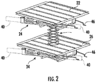
- the adjustment mechanism 28 includes an electrically powered scissor linkage or pantograph (as shown in Figure 2 , for example).
- the second platform 26 in this example embodiment is supported above a lift 30 that the installation personnel may use to reach various heights along the hoistway during elevator system installation.
- the personnel lift 30 can be set in a desired location in the hoistway and held in that position using known equipment.
- Figure 2 shows another embodiment in which the assembly 20 is independent of a personnel lift, such as the lift 30.
- the second platform 26 includes at least one second brace 34 that is configured to engage a support surface for maintaining the second platform 26 at a desired vertical location within the hoistway.
- This example embodiment includes a plurality of second braces 34 associated with the second platform.
- Figure 3 shows an example arrangement of braces for supporting a platform 22, 26 at a desired vertical position in a hoistway.
- Figure 3 shows the second platform 26 of Figure 2 .
- the brace configuration of the first platform 22 is the same as that shown in Figure 3 in the illustrated example embodiments.
- the second braces 34 each include a base 36 that is secured to the second platform 26 beneath the platform. The connection between the base 36 and the second platform 26 is stable and secure. Channel supports 38 are located near opposite ends of the base 36. Moveable portions 40 of the second braces 34 are received in the channel supports 38.
- the moveable portions 40 are metal rods or beams, for example.
- a threaded rod 42 is rotatable relative to the base 36 and the channel supports 38. Threaded followers 44 are coupled with the moveable portions 40. As the threaded rod 42 rotates, the followers 44 move along the threaded rod 42, causing the moveable portions 40 to move along the channel supports 38 between a retracted position shown in Figure 3 to an extended position shown in broken lines in Figure 3 .
- This example embodiment includes handles 46 for manually rotating the threaded rods 42 to selectively adjust the position of the moveable portions 40 relative to the second platform 26.
- Other embodiments include adaptors that allow an individual to use a powered driver or drill to rotate the threaded rods 42.
- the first platform 22 is situated in a selected first vertical location within a hoistway 50.
- the first braces 24 (only one is visible in Figure 4 ) are adjusted so that the moveable portions 40 move from the retracted position shown in Figures 1-3 into an extended position where the moveable portions 40 engage support surfaces for maintaining the first platform 22 at the first vertical location.
- two of the moveable portions 40 extend beyond a first edge 52 of the first platform 22 and two others of the moveable portions 40 extend beyond a second, opposite edge 54 of the first platform 22.
- the moveable portions 40 extending beyond the first edge 52 engage a support surface 56 that corresponds to a landing floor adjacent an opening into the hoistway 50 that eventually will include elevator hoistway doors.
- the moveable portions 40 extending beyond the second edge 54 engage support surfaces in pockets or recesses 58 in a wall of the hoistway 50. At least the moveable portions 40 that engage the support surfaces in the recesses 58 may be considered pawls.
- first braces 24 With the first braces 24 in the condition shown in Figure 4 , the first braces maintain the first platform 22 at the first vertical location.
- the second braces 34 associated with the second platform 26 are similarly situated to engage support surfaces at the second vertical location of the second platform 26.
- Either of the platforms 22, 26 may be secured in the desired vertical location prior to the other. Once one of them is in a desired vertical location, the adjustment mechanism 28 may be used to position the other platform 26, 22 in its desired vertical location while the braces 24, 34 are in the retracted position. Once the platform is in the desired vertical location, the associated braces 24, 34 are moved relative to the platform into the extended position to maintain the platform at that location.
- the braces 24, 34 effectively hold the respective platform 22, 26 in position to withstand the impact of an object that may drop into the hoistway from above the platform assembly 20. Any such object will encounter the first platform 22, protecting anyone beneath the assembly 20. In the event that the first platform 22 does not stop such an object for some reason, the second platform 26 provides redundant or failsafe protection.
- the desired position of the personnel lift 30 sets the vertical location of the second platform 26 within the hoistway.
- the adjustment mechanism 28 selectively adjusts the vertical location of the first platform 22 by raising or lowering the first platform 22 relative to the personnel lift 30 and the second platform 26. Once the first platform 22 is situated at the desired vertical position of the first platform 22, the moveable portions 40 of the first braces 24 are moved outwardly into the extended position like that shown in Figure 4 to secure the first platform 22 in the first vertical location.
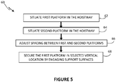
- Figure 5 is a flowchart diagram 60 that summarizes an example method of protecting personnel in a hoistway during an elevator system installation.
- the first platform 22 is situated in a hoistway.
- the second platform 26 is situated in the hoistway.
- the adjustment mechanism 28 adjusts the spacing between the first platform 22 and the second platform 26 at 66.
- the first braces 24 secure the first platform 22 in a selected vertical location in the hoistway by engaging support surfaces.
- the disclosed example embodiments provide an effective and efficient assembly for protecting personnel in a hoistway during elevator system installation, which may occur during ongoing building construction. There is no need for construction workers to be diverted to make and install a special barrier at various levels along the hoistway. Instead, the assembly 20 can be selectively positioned at various locations along the hoistway by the elevator installation personnel.
Landscapes
- Engineering & Computer Science (AREA)
- Structural Engineering (AREA)
- Mechanical Engineering (AREA)
- Civil Engineering (AREA)
- Architecture (AREA)
- Life Sciences & Earth Sciences (AREA)
- Geology (AREA)
- Transportation (AREA)
- Automation & Control Theory (AREA)
- Lift-Guide Devices, And Elevator Ropes And Cables (AREA)
- Types And Forms Of Lifts (AREA)
Applications Claiming Priority (1)
| Application Number | Priority Date | Filing Date | Title |
|---|---|---|---|
| US17/376,528 US11905721B2 (en) | 2021-07-15 | 2021-07-15 | Protective platform assembly for use during elevator installation |
Publications (1)
| Publication Number | Publication Date |
|---|---|
| EP4119481A1 true EP4119481A1 (fr) | 2023-01-18 |
Family
ID=82547300
Family Applications (1)
| Application Number | Title | Priority Date | Filing Date |
|---|---|---|---|
| EP22182695.1A Pending EP4119481A1 (fr) | 2021-07-15 | 2022-07-01 | Ensemble plateforme de protection à utiliser lors de l'installation d'un ascenseur |
Country Status (3)
| Country | Link |
|---|---|
| US (1) | US11905721B2 (fr) |
| EP (1) | EP4119481A1 (fr) |
| CN (1) | CN115611121A (fr) |
Cited By (1)
| Publication number | Priority date | Publication date | Assignee | Title |
|---|---|---|---|---|
| CN119218849A (zh) * | 2024-12-03 | 2024-12-31 | 安徽建工三建集团有限公司 | 井道内施工电梯整体提升的施工设备 |
Families Citing this family (1)
| Publication number | Priority date | Publication date | Assignee | Title |
|---|---|---|---|---|
| CN116730263B (zh) * | 2023-06-06 | 2026-03-20 | 中建八局第一建设有限公司 | 一种基于超高层垂直运输设备的应急救援逃生装置 |
Citations (4)
| Publication number | Priority date | Publication date | Assignee | Title |
|---|---|---|---|---|
| WO2012006693A1 (fr) * | 2010-07-16 | 2012-01-19 | Keersmaekers Marc | Unité de levage pour monter et descendre un échafaudage |
| CN206503349U (zh) * | 2017-01-23 | 2017-09-19 | 江苏弘盛建设工程集团有限公司 | 一种竖向井道无轨自升降自锁式安全笼架 |
| CN109399432A (zh) * | 2018-11-23 | 2019-03-01 | 燕山大学 | 一种自爬升井道作业平台 |
| WO2020142001A1 (fr) * | 2019-01-04 | 2020-07-09 | Em Services Pte Ltd | Plate-forme mobile |
Family Cites Families (6)
| Publication number | Priority date | Publication date | Assignee | Title |
|---|---|---|---|---|
| US3752261A (en) * | 1971-06-21 | 1973-08-14 | S Bushnell | Multi-stage lift |
| US9388020B2 (en) * | 2012-03-06 | 2016-07-12 | Kone Corporation | Method and an elevator arrangement |
| AU2017368776B2 (en) * | 2016-11-30 | 2020-10-22 | Inventio Ag | Lift system and method for constructing such an elevator system |
| US20180265331A1 (en) * | 2017-03-18 | 2018-09-20 | Otis Elevator Company | Elevator commuter boarding system and a method thereof |
| US11122780B2 (en) * | 2017-10-12 | 2021-09-21 | Carson A. Bryant | Apiary system and method of use |
| CN111302187B (zh) * | 2018-12-11 | 2022-09-27 | 奥的斯电梯公司 | 提升组件、跃层电梯和跃层方法 |
-
2021
- 2021-07-15 US US17/376,528 patent/US11905721B2/en active Active
-
2022
- 2022-06-20 CN CN202210697090.9A patent/CN115611121A/zh active Pending
- 2022-07-01 EP EP22182695.1A patent/EP4119481A1/fr active Pending
Patent Citations (5)
| Publication number | Priority date | Publication date | Assignee | Title |
|---|---|---|---|---|
| WO2012006693A1 (fr) * | 2010-07-16 | 2012-01-19 | Keersmaekers Marc | Unité de levage pour monter et descendre un échafaudage |
| US20130112500A1 (en) * | 2010-07-16 | 2013-05-09 | Marc Keersmaekers | Lift Unit for Ascending and Descending a Scaffold |
| CN206503349U (zh) * | 2017-01-23 | 2017-09-19 | 江苏弘盛建设工程集团有限公司 | 一种竖向井道无轨自升降自锁式安全笼架 |
| CN109399432A (zh) * | 2018-11-23 | 2019-03-01 | 燕山大学 | 一种自爬升井道作业平台 |
| WO2020142001A1 (fr) * | 2019-01-04 | 2020-07-09 | Em Services Pte Ltd | Plate-forme mobile |
Cited By (1)
| Publication number | Priority date | Publication date | Assignee | Title |
|---|---|---|---|---|
| CN119218849A (zh) * | 2024-12-03 | 2024-12-31 | 安徽建工三建集团有限公司 | 井道内施工电梯整体提升的施工设备 |
Also Published As
| Publication number | Publication date |
|---|---|
| US20230021058A1 (en) | 2023-01-19 |
| CN115611121A (zh) | 2023-01-17 |
| US11905721B2 (en) | 2024-02-20 |
Similar Documents
| Publication | Publication Date | Title |
|---|---|---|
| EP4119481A1 (fr) | Ensemble plateforme de protection à utiliser lors de l'installation d'un ascenseur | |
| CN105143575B (zh) | 建筑系统 | |
| EP2394006B1 (fr) | Système de construction et procédé pour des bâtiments à plusieurs étages | |
| US20170362895A1 (en) | Access platform system with integrated folding steps | |
| KR20150042185A (ko) | 등반 스크린용 개량 프레임 | |
| EP3257803B1 (fr) | Cabine d'ascenseur et système d'ascenseur | |
| US20190031466A1 (en) | Elevator safety device | |
| EP3484808A1 (fr) | Arrangement d'ascenseur | |
| US20160130115A1 (en) | Retractable overhead access platform for machine room less elevator systems | |
| WO2020142001A1 (fr) | Plate-forme mobile | |
| KR101599698B1 (ko) | 터널 작업 플랫폼 | |
| JP2019112218A (ja) | 人荷昇降装置付き移動昇降式足場並びにこれらを用いた施工方法及びこれらの設置方法 | |
| EP2636627A1 (fr) | Ascenseur | |
| EP4328168A1 (fr) | Dispositif de levage pour cage d'ascenseur de structure en acier de construction et procédé de construction de cage d'ascenseur de structure en acier | |
| JP4389200B2 (ja) | 落橋防止用鋼製ブラケットおよびブロックの取付け装置 | |
| KR102452300B1 (ko) | 천장패널 부착장치 | |
| JP7278863B2 (ja) | 昇降式足場の設置方法 | |
| JP6768630B2 (ja) | エレベーター装置 | |
| SE544679C2 (en) | Installation for secure access to an upper part of a vehicle | |
| WO2017021865A1 (fr) | Élévateur amélioré pour véhicules à moteur | |
| CN113548559A (zh) | 电梯装置 | |
| JP7485218B2 (ja) | かごの移動方法及び嵩上げ装置 | |
| CN220502556U (zh) | 用于录井设备的起落装置 | |
| KR102382816B1 (ko) | 에스컬레이터 제어반의 리프팅 장치 | |
| GB2553122A (en) | Material handling apparatus |
Legal Events
| Date | Code | Title | Description |
|---|---|---|---|
| PUAI | Public reference made under article 153(3) epc to a published international application that has entered the european phase |
Free format text: ORIGINAL CODE: 0009012 |
|
| STAA | Information on the status of an ep patent application or granted ep patent |
Free format text: STATUS: THE APPLICATION HAS BEEN PUBLISHED |
|
| AK | Designated contracting states |
Kind code of ref document: A1 Designated state(s): AL AT BE BG CH CY CZ DE DK EE ES FI FR GB GR HR HU IE IS IT LI LT LU LV MC MK MT NL NO PL PT RO RS SE SI SK SM TR |
|
| STAA | Information on the status of an ep patent application or granted ep patent |
Free format text: STATUS: REQUEST FOR EXAMINATION WAS MADE |
|
| 17P | Request for examination filed |
Effective date: 20230711 |
|
| RBV | Designated contracting states (corrected) |
Designated state(s): AL AT BE BG CH CY CZ DE DK EE ES FI FR GB GR HR HU IE IS IT LI LT LU LV MC MK MT NL NO PL PT RO RS SE SI SK SM TR |
|
| STAA | Information on the status of an ep patent application or granted ep patent |
Free format text: STATUS: EXAMINATION IS IN PROGRESS |
|
| 17Q | First examination report despatched |
Effective date: 20241114 |