EP4119505A1 - Verfahren zur behandlung einer salzhaltigen flüssigkeit und anlage zur durchführung dieses verfahrens - Google Patents
Verfahren zur behandlung einer salzhaltigen flüssigkeit und anlage zur durchführung dieses verfahrens Download PDFInfo
- Publication number
- EP4119505A1 EP4119505A1 EP21305998.3A EP21305998A EP4119505A1 EP 4119505 A1 EP4119505 A1 EP 4119505A1 EP 21305998 A EP21305998 A EP 21305998A EP 4119505 A1 EP4119505 A1 EP 4119505A1
- Authority
- EP
- European Patent Office
- Prior art keywords
- enclosure
- weight
- fluid
- dryer
- installation
- Prior art date
- Legal status (The legal status is an assumption and is not a legal conclusion. Google has not performed a legal analysis and makes no representation as to the accuracy of the status listed.)
- Pending
Links
- 239000012530 fluid Substances 0.000 title claims abstract description 93
- 238000000034 method Methods 0.000 title claims abstract description 57
- 238000009434 installation Methods 0.000 title claims abstract description 39
- 150000003839 salts Chemical class 0.000 title claims description 55
- 238000012545 processing Methods 0.000 title description 2
- 238000011049 filling Methods 0.000 claims abstract description 48
- 238000001035 drying Methods 0.000 claims abstract description 42
- 239000007787 solid Substances 0.000 claims abstract description 28
- 239000000843 powder Substances 0.000 claims abstract description 19
- 230000008569 process Effects 0.000 claims abstract description 16
- 230000007423 decrease Effects 0.000 claims abstract description 10
- XLYOFNOQVPJJNP-UHFFFAOYSA-N water Substances O XLYOFNOQVPJJNP-UHFFFAOYSA-N 0.000 claims description 26
- 239000013529 heat transfer fluid Substances 0.000 claims description 10
- 238000001704 evaporation Methods 0.000 claims description 8
- 230000008020 evaporation Effects 0.000 claims description 8
- 239000008237 rinsing water Substances 0.000 claims description 7
- 230000000295 complement effect Effects 0.000 claims 1
- 239000002826 coolant Substances 0.000 claims 1
- 238000005121 nitriding Methods 0.000 description 39
- 239000012071 phase Substances 0.000 description 32
- 230000003647 oxidation Effects 0.000 description 20
- 238000007254 oxidation reaction Methods 0.000 description 20
- 238000011282 treatment Methods 0.000 description 19
- 238000010791 quenching Methods 0.000 description 18
- 238000001914 filtration Methods 0.000 description 15
- 239000002699 waste material Substances 0.000 description 11
- 239000002245 particle Substances 0.000 description 10
- 238000000605 extraction Methods 0.000 description 9
- 230000000171 quenching effect Effects 0.000 description 9
- 230000000875 corresponding effect Effects 0.000 description 8
- FAPWRFPIFSIZLT-UHFFFAOYSA-M Sodium chloride Chemical compound [Na+].[Cl-] FAPWRFPIFSIZLT-UHFFFAOYSA-M 0.000 description 7
- 239000003643 water by type Substances 0.000 description 7
- 238000007792 addition Methods 0.000 description 6
- 238000000889 atomisation Methods 0.000 description 5
- 239000007788 liquid Substances 0.000 description 5
- 238000012360 testing method Methods 0.000 description 5
- QGZKDVFQNNGYKY-UHFFFAOYSA-N Ammonia Chemical compound N QGZKDVFQNNGYKY-UHFFFAOYSA-N 0.000 description 4
- 229910000831 Steel Inorganic materials 0.000 description 4
- 239000007789 gas Substances 0.000 description 4
- 239000006249 magnetic particle Substances 0.000 description 4
- 230000001590 oxidative effect Effects 0.000 description 4
- 239000010959 steel Substances 0.000 description 4
- 238000009833 condensation Methods 0.000 description 3
- 230000005494 condensation Effects 0.000 description 3
- 238000010981 drying operation Methods 0.000 description 3
- 238000010438 heat treatment Methods 0.000 description 3
- 238000003860 storage Methods 0.000 description 3
- 238000011144 upstream manufacturing Methods 0.000 description 3
- 238000005303 weighing Methods 0.000 description 3
- IJGRMHOSHXDMSA-UHFFFAOYSA-N Atomic nitrogen Chemical compound N#N IJGRMHOSHXDMSA-UHFFFAOYSA-N 0.000 description 2
- 101100165177 Caenorhabditis elegans bath-15 gene Proteins 0.000 description 2
- 229910021529 ammonia Inorganic materials 0.000 description 2
- 230000003416 augmentation Effects 0.000 description 2
- 230000015572 biosynthetic process Effects 0.000 description 2
- 230000015556 catabolic process Effects 0.000 description 2
- 230000008859 change Effects 0.000 description 2
- 239000012141 concentrate Substances 0.000 description 2
- 230000001276 controlling effect Effects 0.000 description 2
- 238000001816 cooling Methods 0.000 description 2
- 230000005484 gravity Effects 0.000 description 2
- 231100001261 hazardous Toxicity 0.000 description 2
- 238000005470 impregnation Methods 0.000 description 2
- UQSXHKLRYXJYBZ-UHFFFAOYSA-N iron oxide Inorganic materials [Fe]=O UQSXHKLRYXJYBZ-UHFFFAOYSA-N 0.000 description 2
- 235000013980 iron oxide Nutrition 0.000 description 2
- VBMVTYDPPZVILR-UHFFFAOYSA-N iron(2+);oxygen(2-) Chemical class [O-2].[Fe+2] VBMVTYDPPZVILR-UHFFFAOYSA-N 0.000 description 2
- 239000010808 liquid waste Substances 0.000 description 2
- 238000005259 measurement Methods 0.000 description 2
- 238000006386 neutralization reaction Methods 0.000 description 2
- 150000002823 nitrates Chemical class 0.000 description 2
- 150000002826 nitrites Chemical class 0.000 description 2
- 238000011084 recovery Methods 0.000 description 2
- 238000007790 scraping Methods 0.000 description 2
- 239000010802 sludge Substances 0.000 description 2
- 239000011780 sodium chloride Substances 0.000 description 2
- 231100000331 toxic Toxicity 0.000 description 2
- 230000002588 toxic effect Effects 0.000 description 2
- 241001080024 Telles Species 0.000 description 1
- 238000013459 approach Methods 0.000 description 1
- 238000005119 centrifugation Methods 0.000 description 1
- 230000002596 correlated effect Effects 0.000 description 1
- 238000005260 corrosion Methods 0.000 description 1
- 230000007797 corrosion Effects 0.000 description 1
- 238000002425 crystallisation Methods 0.000 description 1
- 230000008025 crystallization Effects 0.000 description 1
- 238000005238 degreasing Methods 0.000 description 1
- 238000010612 desalination reaction Methods 0.000 description 1
- 238000010586 diagram Methods 0.000 description 1
- 238000009792 diffusion process Methods 0.000 description 1
- 239000000428 dust Substances 0.000 description 1
- 238000005516 engineering process Methods 0.000 description 1
- 235000021183 entrée Nutrition 0.000 description 1
- 229910000856 hastalloy Inorganic materials 0.000 description 1
- 208000020442 loss of weight Diseases 0.000 description 1
- 238000004519 manufacturing process Methods 0.000 description 1
- 239000000463 material Substances 0.000 description 1
- 238000002844 melting Methods 0.000 description 1
- 230000008018 melting Effects 0.000 description 1
- 239000002184 metal Substances 0.000 description 1
- 229910052751 metal Inorganic materials 0.000 description 1
- 239000000203 mixture Substances 0.000 description 1
- 229910052757 nitrogen Inorganic materials 0.000 description 1
- 235000011837 pasties Nutrition 0.000 description 1
- 238000003672 processing method Methods 0.000 description 1
- 238000005086 pumping Methods 0.000 description 1
- 239000002994 raw material Substances 0.000 description 1
- 238000004064 recycling Methods 0.000 description 1
- 230000009467 reduction Effects 0.000 description 1
- 230000000717 retained effect Effects 0.000 description 1
- 239000013535 sea water Substances 0.000 description 1
- 239000002002 slurry Substances 0.000 description 1
- 239000007790 solid phase Substances 0.000 description 1
- 239000007921 spray Substances 0.000 description 1
- 230000007704 transition Effects 0.000 description 1
- 239000011800 void material Substances 0.000 description 1
- 238000000207 volumetry Methods 0.000 description 1
Images


Classifications
-
- C—CHEMISTRY; METALLURGY
- C02—TREATMENT OF WATER, WASTE WATER, SEWAGE, OR SLUDGE
- C02F—TREATMENT OF WATER, WASTE WATER, SEWAGE, OR SLUDGE
- C02F1/00—Treatment of water, waste water, or sewage
- C02F1/02—Treatment of water, waste water, or sewage by heating
- C02F1/04—Treatment of water, waste water, or sewage by heating by distillation or evaporation
- C02F1/048—Purification of waste water by evaporation
-
- B—PERFORMING OPERATIONS; TRANSPORTING
- B01—PHYSICAL OR CHEMICAL PROCESSES OR APPARATUS IN GENERAL
- B01D—SEPARATION
- B01D1/00—Evaporating
- B01D1/0064—Feeding of liquid into an evaporator
-
- B—PERFORMING OPERATIONS; TRANSPORTING
- B01—PHYSICAL OR CHEMICAL PROCESSES OR APPARATUS IN GENERAL
- B01D—SEPARATION
- B01D1/00—Evaporating
- B01D1/0064—Feeding of liquid into an evaporator
- B01D1/0076—Maintaining the liquid in the evaporator at a constant level
-
- B—PERFORMING OPERATIONS; TRANSPORTING
- B01—PHYSICAL OR CHEMICAL PROCESSES OR APPARATUS IN GENERAL
- B01D—SEPARATION
- B01D1/00—Evaporating
- B01D1/22—Evaporating by bringing a thin layer of the liquid into contact with a heated surface
- B01D1/222—In rotating vessels; vessels with movable parts
- B01D1/223—In rotating vessels; vessels with movable parts containing a rotor
- B01D1/225—In rotating vessels; vessels with movable parts containing a rotor with blades or scrapers
-
- B—PERFORMING OPERATIONS; TRANSPORTING
- B01—PHYSICAL OR CHEMICAL PROCESSES OR APPARATUS IN GENERAL
- B01D—SEPARATION
- B01D1/00—Evaporating
- B01D1/22—Evaporating by bringing a thin layer of the liquid into contact with a heated surface
- B01D1/24—Evaporating by bringing a thin layer of the liquid into contact with a heated surface to obtain dry solids
-
- B—PERFORMING OPERATIONS; TRANSPORTING
- B01—PHYSICAL OR CHEMICAL PROCESSES OR APPARATUS IN GENERAL
- B01D—SEPARATION
- B01D3/00—Distillation or related exchange processes in which liquids are contacted with gaseous media, e.g. stripping
- B01D3/10—Vacuum distillation
-
- B—PERFORMING OPERATIONS; TRANSPORTING
- B01—PHYSICAL OR CHEMICAL PROCESSES OR APPARATUS IN GENERAL
- B01D—SEPARATION
- B01D3/00—Distillation or related exchange processes in which liquids are contacted with gaseous media, e.g. stripping
- B01D3/10—Vacuum distillation
- B01D3/106—Vacuum distillation with the use of a pump for creating vacuum and for removing the distillate
-
- B—PERFORMING OPERATIONS; TRANSPORTING
- B01—PHYSICAL OR CHEMICAL PROCESSES OR APPARATUS IN GENERAL
- B01D—SEPARATION
- B01D5/00—Condensation of vapours; Recovering volatile solvents by condensation
- B01D5/0057—Condensation of vapours; Recovering volatile solvents by condensation in combination with other processes
- B01D5/006—Condensation of vapours; Recovering volatile solvents by condensation in combination with other processes with evaporation or distillation
-
- C—CHEMISTRY; METALLURGY
- C02—TREATMENT OF WATER, WASTE WATER, SEWAGE, OR SLUDGE
- C02F—TREATMENT OF WATER, WASTE WATER, SEWAGE, OR SLUDGE
- C02F1/00—Treatment of water, waste water, or sewage
- C02F1/008—Control or steering systems not provided for elsewhere in subclass C02F
-
- C—CHEMISTRY; METALLURGY
- C02—TREATMENT OF WATER, WASTE WATER, SEWAGE, OR SLUDGE
- C02F—TREATMENT OF WATER, WASTE WATER, SEWAGE, OR SLUDGE
- C02F1/00—Treatment of water, waste water, or sewage
- C02F1/02—Treatment of water, waste water, or sewage by heating
- C02F1/04—Treatment of water, waste water, or sewage by heating by distillation or evaporation
- C02F1/043—Details
-
- F—MECHANICAL ENGINEERING; LIGHTING; HEATING; WEAPONS; BLASTING
- F28—HEAT EXCHANGE IN GENERAL
- F28D—HEAT-EXCHANGE APPARATUS, NOT PROVIDED FOR IN ANOTHER SUBCLASS, IN WHICH THE HEAT-EXCHANGE MEDIA DO NOT COME INTO DIRECT CONTACT
- F28D1/00—Heat-exchange apparatus having stationary conduit assemblies for one heat-exchange medium only, the media being in contact with different sides of the conduit wall, in which the other heat-exchange medium is a large body of fluid, e.g. domestic or motor car radiators
- F28D1/06—Heat-exchange apparatus having stationary conduit assemblies for one heat-exchange medium only, the media being in contact with different sides of the conduit wall, in which the other heat-exchange medium is a large body of fluid, e.g. domestic or motor car radiators with the heat-exchange conduits forming part of, or being attached to, the tank containing the body of fluid
-
- F—MECHANICAL ENGINEERING; LIGHTING; HEATING; WEAPONS; BLASTING
- F28—HEAT EXCHANGE IN GENERAL
- F28F—DETAILS OF HEAT-EXCHANGE AND HEAT-TRANSFER APPARATUS, OF GENERAL APPLICATION
- F28F13/00—Arrangements for modifying heat-transfer, e.g. increasing, decreasing
- F28F13/06—Arrangements for modifying heat-transfer, e.g. increasing, decreasing by affecting the pattern of flow of the heat-exchange media
- F28F13/12—Arrangements for modifying heat-transfer, e.g. increasing, decreasing by affecting the pattern of flow of the heat-exchange media by creating turbulence, e.g. by stirring, by increasing the force of circulation
- F28F13/125—Arrangements for modifying heat-transfer, e.g. increasing, decreasing by affecting the pattern of flow of the heat-exchange media by creating turbulence, e.g. by stirring, by increasing the force of circulation by stirring
-
- C—CHEMISTRY; METALLURGY
- C02—TREATMENT OF WATER, WASTE WATER, SEWAGE, OR SLUDGE
- C02F—TREATMENT OF WATER, WASTE WATER, SEWAGE, OR SLUDGE
- C02F11/00—Treatment of sludge; Devices therefor
- C02F11/12—Treatment of sludge; Devices therefor by de-watering, drying or thickening
- C02F11/13—Treatment of sludge; Devices therefor by de-watering, drying or thickening by heating
-
- C—CHEMISTRY; METALLURGY
- C02—TREATMENT OF WATER, WASTE WATER, SEWAGE, OR SLUDGE
- C02F—TREATMENT OF WATER, WASTE WATER, SEWAGE, OR SLUDGE
- C02F2101/00—Nature of the contaminant
- C02F2101/10—Inorganic compounds
- C02F2101/16—Nitrogen compounds, e.g. ammonia
-
- C—CHEMISTRY; METALLURGY
- C02—TREATMENT OF WATER, WASTE WATER, SEWAGE, OR SLUDGE
- C02F—TREATMENT OF WATER, WASTE WATER, SEWAGE, OR SLUDGE
- C02F2103/00—Nature of the water, waste water, sewage or sludge to be treated
- C02F2103/16—Nature of the water, waste water, sewage or sludge to be treated from metallurgical processes, i.e. from the production, refining or treatment of metals, e.g. galvanic wastes
-
- C—CHEMISTRY; METALLURGY
- C02—TREATMENT OF WATER, WASTE WATER, SEWAGE, OR SLUDGE
- C02F—TREATMENT OF WATER, WASTE WATER, SEWAGE, OR SLUDGE
- C02F2301/00—General aspects of water treatment
- C02F2301/06—Pressure conditions
- C02F2301/063—Underpressure, vacuum
-
- C—CHEMISTRY; METALLURGY
- C02—TREATMENT OF WATER, WASTE WATER, SEWAGE, OR SLUDGE
- C02F—TREATMENT OF WATER, WASTE WATER, SEWAGE, OR SLUDGE
- C02F2301/00—General aspects of water treatment
- C02F2301/08—Multistage treatments, e.g. repetition of the same process step under different conditions
-
- F—MECHANICAL ENGINEERING; LIGHTING; HEATING; WEAPONS; BLASTING
- F28—HEAT EXCHANGE IN GENERAL
- F28F—DETAILS OF HEAT-EXCHANGE AND HEAT-TRANSFER APPARATUS, OF GENERAL APPLICATION
- F28F5/00—Elements specially adapted for movement
- F28F5/04—Hollow impellers, e.g. stirring vane
Definitions
- the invention relates to a method for treating a fluid, in particular a fluid containing salts, called “saline solution”, in particular at a low or medium salt concentration, that is to say having for example a salts less than 500 g/L, or even 300 g/L.
- the invention also relates to an installation making it possible to implement such a method.
- parts for example made of steel, are generally treated in batches of several parts, also called by batch, on a nitriding line.
- the parts to be treated are degreased, then rinsed and dried in an oven.
- a nitriding bath in a tank (also called crucible), at high temperature (for example of the order of 500-650°C).
- a nitriding bath is generally composed mainly of molten nitriding salts.
- nitriding is, for example, to give the parts a higher surface hardness and to improve their mechanical properties, for example by diffusion of nitrogen into the steel of steel parts.
- the parts are optionally immersed in an oxidation bath, in a tank (also called a crucible), for example at around 450°C.
- an oxidation bath is generally composed mainly of molten oxidizing salts.
- the purpose of oxidation is, for example, to improve the corrosion resistance of parts. It generally gives them a uniform black appearance.
- the parts undergo a quenching operation, for example in a water tank at a temperature much lower than that of the bath, i.e. relatively cold.
- the water in the rinsing or quenching tanks (also called “breakdown water”) is also enriched in oxidation and/or nitriding salts, for example in nitrates and nitrites.
- sludge which also contains nitriding and/or oxidation salts.
- the particle size of the recovered salt must not be too fine in order to avoid the problem of volatility of the powder, nor too large (for example greater than 1 cm) because a larger grain retains residual water more easily. It can then be dangerous to use such a salt for example for treatments in a molten salt bath, because the instantaneous evaporation of the water during the melting of the salt can give rise to projections of molten salt.
- Tests were carried out with a vacuum evaporator-concentrator with scraper. The process made it possible to obtain a concentrate with approximately 30% humidity, which cannot be used as it is for application to a nitriding/oxidation line. An additional drying step is then necessary to obtain a powder with a dryness of at least 95%, or even if possible of at least 98%. A centrifugation test failed to obtain the required dryness. This two-step approach was therefore not retained.
- Atomization consists of drying a solution introduced through a nozzle, by a stream of hot air in an atomization tower; the droplets are instantly dried and the powder is collected in a cyclone.
- Tests with a single-effect atomizer produced powders with a characteristic size of between 30 ⁇ m and 50 ⁇ m, which is much too fine for the intended use objectives.
- Flash atomization is based on the same principle as an atomization tower but is characterized by a toroidal drying chamber allowing to accelerate the drying of the particles, with a more compact equipment.
- the known processes therefore produce powders that are too fine, or at too high a humidity level, or are too expensive, or are not suitable for treating multi-component salts.
- the present invention thus aims to overcome, at least in part, the aforementioned drawbacks, further leading to other advantages.
- the fluid to be dried can, for example, come from a solution aqueous saline from a tank of a nitriding production line, for example a quench tank.
- the fluid to be treated, the saline solution can be multi-component and include very soluble salts.
- the fluid to be dried initially has a salt concentration of less than 500 g/L, for example between 50 g/L and 500 g/L, or even for example between 300 g/L and 400 g/L.
- Such a process thus makes it possible to recover the salts contained in the fluids originating from a nitriding line, for example in the quenching waters and/or the sludges, and thus to reduce the waste; Incidentally, certain treatment costs are thus controlled.
- Such a method makes it possible to eliminate quantities of fluid waste since these are recycled, at least in part, or even entirely as far as possible, to extract the salts contained in these fluids following the successive passages of parts in at least a vat from which they come.
- the enclosure of the dryer is for example kept under vacuum.
- the vacuum denotes for example here a pressure of between about 10 mbar and 900 mbar (millibar), for example between 20 mbar and 500 mbar, or even between 20 mbar and 100 mbar.
- Such a vacuum makes it possible to evaporate the water from the saline solution at relatively low temperatures, for example between 35°C and 90°C. It can also be used to suck up the fluid to be treated.
- the additional filling during the drying step thus allows a semi-continuous filling of the enclosure, that is to say a filling such that the fluid to be treated is added to the enclosure of the dryer while the enclosure is void due to processing.
- the first phase of the drying step comprises at least one cycle in which the fluid is concentrated while vapors are evaporated, until the weight of the enclosure reaches a low threshold or its rate of variation is less than a first predefined value, then additional filling is performed.
- part of the fluid in particular the water in the fluid, evaporates, and consequently, the weight of the content of the pregnant decreases.
- the dryer comprises a system of load cells configured to control a weight of fluid contained in the enclosure.
- the valve is opened to introduce the fluid to be treated.
- a certain threshold called low threshold
- a rate of variation of the weight of the enclosure is lower than a first predefined value (i.e. the variation in weight decreases over a given time interval)
- the valve is opened to introduce the fluid to be treated.
- the weight is greater than this threshold, or varies more than the first predefined value, then the enclosure is considered sufficiently filled, and the evaporation follows its course.
- the low threshold is chosen so that the addition of fluid has a low impact on the temperature of the contents of the enclosure (for example, the temperature varies less than 20%, even 15%, even less than 10% or even 5%, or even less than 3% relative to the average temperature of the contents of the enclosure before addition); for example, the low threshold is chosen to represent approximately 85% of the maximum volume of the enclosure.
- the thresholds are for example determined for each additional filling so as to represent a substantially constant filling volume. Indeed, as the drying step progresses, the fluid concentrates in salt in the enclosure. The same volume therefore weighs more and more. Therefore, the threshold value may vary from one additional filling to another.
- the method comprises a step of controlling a weight of the enclosure, and when the weight reaches the low threshold or the rate of variation of the weight of the enclosure is less than the first predefined value, the method comprises a step of opening a filling valve and the step of additional filling of fluid to be treated in the enclosure is implemented.
- the method includes a step of closing the filling valve.
- the load cell system is also configured to detect the end of drying, at the end of the second phase. For example, when the weight of the loudspeaker remains relatively constant over time (that is to say that the variation in the weight of the loudspeaker over time becomes less than a second predefined value), it is then considered that any the water has been evaporated and the product is “dry” (has reached a target dryness level).
- the first predefined value and the second predefined value can be equal or different, for example the second predefined value can be lower than the first predefined value; for example the second predefined value can be close to zero. For example, after a predefined number of additional fillings, or the enclosure reaches a certain weight, then the second phase is implemented.
- the additional fillings of the first phase are repeated until a salt concentration in the fluid contained in the enclosure reaches a target value; for example at least 400 g/L, preferably at least 500 g/L for oxidation and/or nitriding salts, but the target value obviously depends on the nature of the salts and/or the applications considered.
- a target value for example at least 400 g/L, preferably at least 500 g/L for oxidation and/or nitriding salts, but the target value obviously depends on the nature of the salts and/or the applications considered.
- the drying step is configured to produce the solid residue having a moisture content of between 0.5% and 5%, by weight, or even between 0.5% and 3%, or even between 1% at 2%.
- the humidity level is for example monitored by a thermal balance, for example on a sample of solid residue taken.
- the drying step is configured to produce the solid residue having a specific particle size.
- the solid residue is in the form of a powder with a grain diameter of between 100 ⁇ m and 1000 ⁇ m, for example between 200 ⁇ m and 500 ⁇ m, on average.
- the particle size should not be too fine in order to avoid the problem of volatility of the powder, nor too large (for example greater than 1 cm) because a larger grain retains residual water more easily.
- the drying step includes a crumbling step.
- Such a step aims to limit, or even avoid, the formation of a clod in the enclosure.
- the method includes a step of condensing the steam from the dryer, producing a condensate.
- the method then also allows a reduction in water consumption by reusing the condensate.
- the method then comprises a step of injecting the condensate into a tank, for example a tank of rinsing water.
- the condensate obtained can thus be used as rinsing water.
- the vapor condensation step is for example implemented in a condenser.
- the method includes a gas absorption-neutralization step generated during the vapor condensation step by an absorber-neutralizer, also called a scrubber.
- the method comprises a step of extracting fluid to be treated from a tank of a nitriding line, or even for example from a storage tank.
- the method includes a step of filtering the fluid to be treated before the step of introducing it into the enclosure of the dryer.
- the filtration step comprises for example a step of passing the fluid through a sieve with a mesh size less than or equal to 50 ⁇ m, for example between 2 ⁇ m and 50 ⁇ m.
- the filtration step includes, for example, a step of removing particles using a magnetic bar.
- such a magnetic bar picks up magnetic particles, in particular for example iron oxides.
- the invention also relates to an installation configured to implement a method comprising at least some of the steps described above.
- the installation comprises at least one dryer, which is configured to implement at least the drying step.
- the dryer mainly comprises an enclosure.
- the enclosure is for example generally cylindrical in shape.
- the enclosure is for example a non-rotating enclosure.
- the enclosure includes at least one inlet for fluid to be dried, configured to introduce fluid to be dried into the enclosure.
- the enclosure includes at least one solid residue discharge outlet.
- the enclosure includes at least one steam outlet.
- the dryer comprises a mixer, in particular a helical mixer heated, for example by circulation of a heat transfer fluid.
- the mixer is configured to rotate in the enclosure, for example at a moderate speed, for example up to 100 rpm, for example between 1 rpm and 100 rpm (revolutions per minute), by example between 1 and 25 rpm, which makes it possible to mix, in a sufficiently homogeneous manner here, the fluid to be dried and to improve its contact with a wall of the enclosure.
- a moderate speed for example up to 100 rpm, for example between 1 rpm and 100 rpm (revolutions per minute), by example between 1 and 25 rpm, which makes it possible to mix, in a sufficiently homogeneous manner here, the fluid to be dried and to improve its contact with a wall of the enclosure.
- the mixer passes for example at a distance from the wall of the enclosure in order to avoid scraping the wall and thus limit wear of the mixer.
- the enclosure has a conical bottom.
- Such a conical bottom facilitates the unloading of the solid residue obtained.
- the solid residue (eg in powder form) is discharged from the dryer enclosure by gravity.
- the conical bottom has the solid residue unloading outlet.
- a traditional dryer is usually provided for batch operation, to dry dry pasty products, with a filling rate of 60% to 100% of a volume of the enclosure.
- the dryer considered here then makes it possible to work in “semi-continuous” mode.
- it comprises for example a system of load cells.
- Such a system of weights is configured to weigh the enclosure, possibly continuously, and incidentally to weigh the contents of the enclosure.
- the weighing system comprises at least one weighing sensor.
- the enclosure In order to correctly measure the weight of the enclosure, it is preferably mechanically decoupled from the rest of the installation, for example by using flexible conduits on the inputs and outputs.
- a loss in weight of the contents of the enclosure, in particular due to evaporation of water from the treated fluid, can then be compensated for by adding fluid to be treated. This also makes it possible to increase a salt concentration of the fluid contained in the enclosure as the drying operation progresses.
- the volume of the dry residue thus obtained in the end is of the order of 50% to 75% of the volume of the enclosure, or even greater than 80% and ideally greater than 90%.
- This “semi-continuous” filling operation can be fully automated: the number of additions and the quantity of fluid per addition can for example be configurable.
- the additions of fluid are made during drying: the fluid is "sucked up", for example by pressure difference from a tank, for example a storage tank or buffer tank, connected to the dryer, without breaking the vacuum of the enclosure .
- the dryer has at least one filling valve.
- the filling valve is configured to be opened when a weight of the enclosure reaches a low threshold or when a rate of variation of the weight of the enclosure is lower than a first predefined value, and to be closed when the enclosure weight reaches a high threshold or when enclosure filling reaches its maximum level.
- the weight, measured by the load cell system, is for example correlated to the degree of filling of the enclosure.
- the installation comprises a control system configured to control an opening or a closing of the at least one filling valve as a function of a weight of the enclosure measured by the load cell system.
- the enclosure comprises a wall formed of a double envelope.
- the double envelope is for example configured to cause a heat transfer fluid to circulate therein.
- the heat transfer fluid is for example configured to maintain a temperature of between 30° C. and 90° C. in the enclosure where the fluid is treated.
- the dryer is a vacuum agitated vertical mixer dryer.
- the enclosure of the dryer comprises a lump breaker configured to limit the formation of a clod in the fluid treated in the enclosure.
- This lump breaker is for example a knife lump breaker, placed at the bottom of the enclosure.
- Such a lump breaker is for example configured to rotate up to a speed of 1500 rpm.
- the installation comprises an extraction system configured to convey the fluid to be treated from a reservoir, for example a tank of a nitriding line, to the dryer.
- a reservoir for example a tank of a nitriding line
- the extraction system includes a filtration system.
- the filtration system comprises for example a sieve with a mesh of less than or equal to 50 ⁇ m, for example between 2 ⁇ m and 50 ⁇ m, or even for example between 5 ⁇ m and 10 ⁇ m.
- the filtration system further comprises a magnetic bar, which is for example configured to eliminate magnetic particles which would be contained in the fluid to be treated.
- the steam outlet of the dryer is equipped with a filter.
- the filter is for example configured to filter vapors.
- the filter comprises for example a filter cartridge, for example with unclogging with compressed air.
- the filter retains, for example, ultra-fine powders. Unclogging removes these powders and thus restores the filter's efficiency.
- the unclogged powders fall back by gravity into the enclosure of the dryer.
- the installation comprises a boiler configured to maintain the enclosure of the dryer at the desired temperature.
- the boiler is for example configured to heat up to approximately 130° C. the heat transfer fluid circulating in the double envelope of the enclosure, as well as in the helical mixer.
- the boiler is configured to have a heating mode and a cooling mode to reduce the temperature of the solid residue produced.
- the installation includes a vacuum module.
- the vacuum module is configured to produce a moderate vacuum in the enclosure of the dryer, that is to say a pressure of between 10 mbar and 900 mbar, for example between 20 mbar and 500 mbar, or even between 20 mbar and 100 mbar.
- Such a pressure assimilated to a vacuum, thus makes it possible to evaporate water from the fluid at low temperature, that is to say at a temperature between 30° C. and 90° C.
- the vacuum module is for example connected to the steam outlet of the dryer.
- the vacuum module includes at least one vacuum pump.
- the installation further comprises a condenser.
- the condenser is for example configured to condense the vapors coming from the dryer via the vapor outlet and to produce a condensate.
- the condenser is for example connected to a steam outlet of the dryer.
- the condenser is for example a tube bundle condenser.
- the installation thus makes it possible to recover water, which can be reused.
- the installation comprises a cooler.
- a tubular heat exchanger is connected to the chiller.
- the installation includes a condensate tank configured to collect the condensed vapours.
- the installation comprises a condensate feed pipe configured to extract the condensate from the condenser and possibly reinject it into a tank, for example a rinsing water tank.
- the condensate supply line includes a filter.
- the installation here also comprises an absorber-neutralizer, commonly called a scrubber.
- the scrubber is connected to the condenser and makes it possible to reduce or even eliminate any presence of toxic or corrosive gases, possibly contained in the condensate (for example ammonia for nitriding).
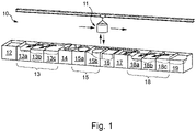
- the figure 1 shows an example of a nitriding line 10.
- Parts for example made of steel, are arranged in a cage 11 in order to be processed in batches of several parts, also called by batch.
- the cage 11 is for example immersed in a first tank 12 containing a degreasing bath.
- nitriding bath 15 is generally composed mainly of molten nitriding salts, at a temperature of approximately 500-650°C.
- an oxidation bath 16 is generally composed mainly of molten oxidizing salts, at a temperature of approximately 450° C.
- the parts undergo a quenching operation, for example in a quenching water tank 17, at a temperature much lower than that of the bath, i.e. relatively cold.
- the parts are rinsed in a post-treatment rinsing tank 18, or several tanks 18a, 18b, 18c in cascade.
- impregnation treatments can be applied, such as impregnation.
- the cage can then then be immersed in an impregnation bath 19 for example.
- sludge is secreted into the nitriding 15 and/or oxidation 16 baths, which contain nitriding and/or oxidation salts.
- the water in the post-treatment rinsing 18 or quenching 17 tanks (also called “breakdown water”) is also enriched in oxidation and/or nitriding salts, for example in nitrates and nitrites.
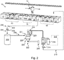
- the picture 2 shows an example of an installation 200 making it possible to treat this waste at least in part and to recycle the salts which it contains.
- a fluid containing salts is extracted from the quench tank 17, but it could of course be any other tank containing a fluid corresponding to a saline solution.
- the installation 200 mainly comprises a dryer 220, shown schematically in more detail picture 3 .
- the installation here first comprises an extraction system 201.
- the extraction system 201 comprises for example a buffer tank 203, and at least one upstream pipe 202, leading from the tank from which the fluid to be treated is extracted to the buffer tank 203.
- the upstream pipe 202 here includes, for example, a filtration system 205.
- the filtration system 205 comprises for example a sieve with a mesh of less than or equal to 50 ⁇ m, for example between 2 ⁇ m and 50 ⁇ m, or even for example between 5 ⁇ m and 10 ⁇ m.
- the filtration system 205 further comprises a magnetic bar, which is for example configured to eliminate magnetic particles which would be contained in the fluid to be treated.
- the extraction system 201 Downstream of the buffer tank 203, the extraction system 201 comprises for example at least one downstream pipe 204, leading from the buffer tank 203 to the dryer 220, in particular to an inlet of fluid to be dried 221 of the dryer 220.
- the dryer 220 here comprises at least two outlets 222, 223: a solid residue discharge outlet 222 and a steam outlet 223.
- the steam outlet 223 has two parallel paths which are connected to a vacuum module 207.
- a first of the two paths from the steam outlet 223 is for example provided with a filter 224.
- the filter 224 is for example configured to filter vapors.
- the filter 224 comprises for example a filter cartridge, for example with unclogging with compressed air.
- the vapors are condensed directly without passing through the filter 224, that is to say passing through a second of the two paths coming from the vapor outlet 223 and leading to the vacuum model 207.
- the filter 224 is therefore for example activated during phase C of the method.
- the installation also includes, for example, a boiler 206 configured to maintain an enclosure of the dryer at the desired temperature.
- the boiler 206 is for example configured to heat up to approximately 130° C. a heat transfer fluid configured to maintain an interior of the enclosure at a desired temperature.
- the boiler 206 can be switched to heating or cooling mode to reduce the temperature of the solid residue produced in the enclosure during a discharge phase, via the solid residue discharge outlet 222.
- the installation Downstream of the dryer, the installation then includes the vacuum module 207 to which the steam outlet 223 is connected.
- the vacuum module comprises for example at least one vacuum pump configured to produce a moderate vacuum in an enclosure of the dryer 220, that is to say a pressure of between 10 mbar and 900 mbar.
- the vacuum module comprises for example two pumps which can be used in series or individually (depending on the application and the efficiency required): for example a Roots pump, and a liquid ring pump.
- the installation can also comprise a condenser 208 configured to condense the vapors coming from the dryer 220 via the vapor outlet 223.
- the condenser is for example a tube bundle condenser.
- the condenser 208 comprises for example a tubular heat exchanger.
- the installation may also include a cooler 209.
- tubular heat exchanger of the condenser 208 is connected to the chiller 209.
- Condensed vapors can be collected in a condensate tank.
- the installation comprises a condensate feed pipe 210 configured to extract the condensate from the condenser and possibly reinject it into a tank of rinsing water, for example here the rinsing tank 18c.
- the condensate comprises for example liquid water, produced by the condensation of water vapors from the dryer.
- the condensate supply line 210 optionally includes a filter 211.
- the installation here also comprises an absorber-neutralizer 212, commonly called a scrubber 212.
- the scrubber 212 is connected to the condenser 208 and makes it possible to reduce or even eliminate any presence of toxic or corrosive gases.
- Such gases for example ammonia, are possibly contained in the condensate.
- the 220 dryer is shown in more detail on the picture 3 .
- the dryer 220 is configured to dry fluids containing salts, whether liquid or slurry, under vacuum. These fluids are also referred to as saline solutions.
- the dryer 220 is a vacuum dryer, in particular with a heated vertical mixer, rotating at a moderate speed to obtain an upward flow of perimeter product and a renewal of the product in contact with the heated walls of the enclosure.
- the dryer mainly comprises an enclosure 225, which is provided with the fluid inlet to be dried 221, the solid residue discharge outlet 222 and the steam outlet 223.
- the enclosure 225 is here fixed, in the sense that it is not rotatable, and is held by a support 228.
- the enclosure 225 here comprises a conical bottom which facilitates the unloading of the solid residue obtained.
- the solid residue discharge outlet 222 is therefore preferably formed at one end of the conical bottom, at the bottom of the enclosure.
- the solid residue unloading outlet 222 comprises for example a spherical valve with metal-metal contact.
- the enclosure 225 comprises a double envelope, that is to say an outer wall and an inner wall delimiting between them a space allowing circulation of a heat transfer fluid.
- the heat transfer fluid is for example heated by an electric heater such as the boiler 206 to heat it up to 130° C. for example.
- the heat transfer fluid comprises an oil.
- the inner wall thus forms an inner tank, which is for example made of Hastelloy C22, or any equivalent material.
- the dryer here comprises a mixer 226 configured to mix and dry the contents of the enclosure, i.e. the fluid to be treated.
- the mixer comprises for example a helical blade heated by the circulation of a heat transfer fluid.
- the mixer 226 is for example configured to rotate at a variable speed depending on the needs, for example up to 100 rpm.
- the mixer 226 passes here at a distance from the inner wall of the enclosure 225 in order to avoid scraping the wall and thus limit wear of the mixer 226.
- the dryer comprises a lump breaker (chopper) 230 in the enclosure 225; such a lump breaker 230 is for example configured to rotate at a speed of up to 1500 rpm to break up any clods.
- a lump breaker chopper
- the dryer includes a filling valve 227.
- the filling valve 227 is connected to the fluid inlet 221 of the dryer to be dried.
- Fill valve 227 is opened or closed depending on a weight of the enclosure. When it is open, it then allows an introduction of fluid to be treated into the enclosure, via the fluid inlet to be dried 221, by suction of the fluid thanks to the vacuum module 207.
- the dryer has a system of weights 229.
- the load cell system 229 comprises at least two, preferably three, weight sensors regularly spaced around the enclosure. Their measurement values are then for example averaged (or added) to determine a weight of the enclosure, and therefore know its filling state.
- a weight sensor is here schematically arranged between a shoulder of the enclosure and a support part 228.
- the figure 4 illustrates the main steps of a process for treating a fluid comprising salts according to an exemplary implementation of the invention, for example within the framework of an installation as illustrated in the picture 2 .
- the method includes, for example, a sequence of steps as follows.
- the method first comprises a step S1 of extracting fluid to be treated from a tank, here a quenching tank 17 of a nitriding line.
- the fluid to be treated then the quench water containing salts from the previous nitriding and oxidation baths, is routed through the extraction system 201.
- the method comprises for example a step S2 of filtration of the fluid to be treated, for example by the filtration system 205.
- the filtration step S2 here comprises both a step S21 of passing the fluid through the sieve of the filtration system 205 and a step S22 of eliminating magnetic particles, such as iron oxides, by the magnetic bar.
- the method here comprises a step S4 of controlling a weight of the enclosure 225, for example by the system of load cells 229, and when the weight reaches a low threshold (corresponding to a threshold filling bottom) or that a rate of variation of the weight of the enclosure is less than a second predefined value, the method comprises a step S51 of opening the filling valve 227 and the step of additional filling of fluid to be treated in enclosure 225 is implementation.
- the method comprises a step S52 of closing the filling valve 227.
- the interior of the enclosure is maintained under vacuum, which allows a suction of fluid to be treated in the enclosure when the filling valve 227 is open.
- the method here also comprises a step S6 of condensing the steam coming from the dryer 220 through the steam outlet 223 by means of the condenser 208, thus producing a condensate.
- the method comprises a step S7 of absorption-neutralization of the vapor, by the absorber-neutralizer 212.
- the condensate is for example then routed through the condensate supply line 210.
- the method includes a step S8 of filtering the condensate through the filter 211 of the condensate supply line 210.
- the method includes a step S9 of injecting the condensate into the rinsing tank 18c.
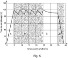
- the figure 5 presents a graph illustrating the treatment of the fluid in the enclosure 225 of the dryer 220 by semi-continuous filling.
- This graph more precisely shows a change in the degree of filling of the enclosure (in %), in ordinates, as a function of time according to an arbitrary unit here, in abscissas.
- This graph here highlights four phases over time: a phase "A” corresponding to step S31 of introducing fluid to be treated into the enclosure 225 of the initially empty dryer 220, a phase “B” corresponding to the first phase of the drying step S32, during which the contents of the enclosure are mainly concentrated in salts, a "C” phase corresponding to the second phase of the drying step S32, and finally a "D” phase which corresponds in step S33 for extracting the solid residue, for example through the solid residue discharge outlet 222.
- Filling is usually done with a lift pump (not shown). The end of filling can be detected by weighing or by volumetry.
- the enclosure is placed under vacuum after the filling of step S31 for introducing fluid to be treated, for example by the vacuum module 207.
- the weight of the enclosure is monitored, for example continuously; reaching a low threshold, or slowing down to reach the first predefined value, triggers the opening of the filling valve 227, the fluid is then sucked up by the vacuum; reaching the high threshold triggers the closing of the valve filling 227.
- the high and low thresholds can change over fillings, in particular to maintain a constant volume filling rate. Indeed, the density of salt can differ from the density of water and the weight depends on the salt content.
- the number of fillings and the variation of the thresholds can be programmed in advance or be controlled entirely by weight, flow rate or salt content measurements.
- the first phase “B” is finished. Then begins the second phase “C" during which there is no more fluid supply.
- the pumping can be reinforced, for example by using a rotary compressor (Roots pump) upstream of the vacuum pump of the vacuum module, which makes it possible to achieve higher dryness rates.
- the weight is also constantly monitored. The loss of weight per unit of time (equivalent to the rate of evaporation) then makes it possible to estimate the rate of remaining humidity and to determine the end of the drying.
- the lump breaker is started, either from the start, or when a certain humidity level is reached.
- a drying operation was carried out on oxidation quench waters from a nitriding chain.
- the solution to be treated had an average concentration of 255 g/L.
- An initial weight of 2324 kg (corresponding to a volume of 1857 L) was introduced into the enclosure of the dryer.
- the enclosure was placed under vacuum (i.e. under approximately 50 mbar) by means of a liquid ring pump.
- the solution was brought to a temperature of 38°C.
- phase C The final drying phase (phase C) was then started until the observation of the liquid-solid phase transition after 21 hours of drying for a dry residue analyzed at 91.67% (dryness rate).
- the changeover to vapor filtration mode was made, the lump breaker was switched on and a vacuum of 10 mbar was reached after the Roots pump was switched on.
Landscapes
- Chemical & Material Sciences (AREA)
- Engineering & Computer Science (AREA)
- Chemical Kinetics & Catalysis (AREA)
- Organic Chemistry (AREA)
- Water Supply & Treatment (AREA)
- Environmental & Geological Engineering (AREA)
- Life Sciences & Earth Sciences (AREA)
- Hydrology & Water Resources (AREA)
- Mechanical Engineering (AREA)
- Physics & Mathematics (AREA)
- Thermal Sciences (AREA)
- General Engineering & Computer Science (AREA)
- Drying Of Solid Materials (AREA)
- Treatment Of Sludge (AREA)
Priority Applications (10)
| Application Number | Priority Date | Filing Date | Title |
|---|---|---|---|
| EP21305998.3A EP4119505A1 (de) | 2021-07-16 | 2021-07-16 | Verfahren zur behandlung einer salzhaltigen flüssigkeit und anlage zur durchführung dieses verfahrens |
| JP2024501231A JP2024525676A (ja) | 2021-07-16 | 2022-07-13 | 塩を含有する流体を処理するための方法及び該方法を実施するための設備 |
| EP22748356.7A EP4370472A1 (de) | 2021-07-16 | 2022-07-13 | Verfahren zur behandlung eines fluids mit salzen und system zur durchführung des verfahrens |
| PCT/EP2022/069573 WO2023285515A1 (fr) | 2021-07-16 | 2022-07-13 | Procédé de traitement d'un fluide comportant des sels et installation pour mettre en oeuvre le procédé |
| KR1020247001178A KR20240037947A (ko) | 2021-07-16 | 2022-07-13 | 염을 포함하는 유체를 처리하기 위한 방법 및 이러한 방법을 구현하기 위한 시스템 |
| CN202280004549.0A CN115812067A (zh) | 2021-07-16 | 2022-07-13 | 处理含盐类的流体的方法以及用于实施该方法的装置 |
| BR112023026168A BR112023026168A2 (pt) | 2021-07-16 | 2022-07-13 | Processo de tratamento para um fluido que compreende sais e instalação para executar o processo |
| MX2024000706A MX2024000706A (es) | 2021-07-16 | 2022-07-13 | Metodo para tratar un fluido que comprende sales y sistema para implementar el metodo. |
| US18/567,800 US20240278147A1 (en) | 2021-07-16 | 2022-07-13 | Method for treating a fluid comprising salts and system for implementing the method |
| CA3220980A CA3220980A1 (fr) | 2021-07-16 | 2022-07-13 | Procede de traitement d'un fluide comportant des sels et installation pour mettre en oeuvre le procede |
Applications Claiming Priority (1)
| Application Number | Priority Date | Filing Date | Title |
|---|---|---|---|
| EP21305998.3A EP4119505A1 (de) | 2021-07-16 | 2021-07-16 | Verfahren zur behandlung einer salzhaltigen flüssigkeit und anlage zur durchführung dieses verfahrens |
Publications (1)
| Publication Number | Publication Date |
|---|---|
| EP4119505A1 true EP4119505A1 (de) | 2023-01-18 |
Family
ID=77739031
Family Applications (2)
| Application Number | Title | Priority Date | Filing Date |
|---|---|---|---|
| EP21305998.3A Pending EP4119505A1 (de) | 2021-07-16 | 2021-07-16 | Verfahren zur behandlung einer salzhaltigen flüssigkeit und anlage zur durchführung dieses verfahrens |
| EP22748356.7A Pending EP4370472A1 (de) | 2021-07-16 | 2022-07-13 | Verfahren zur behandlung eines fluids mit salzen und system zur durchführung des verfahrens |
Family Applications After (1)
| Application Number | Title | Priority Date | Filing Date |
|---|---|---|---|
| EP22748356.7A Pending EP4370472A1 (de) | 2021-07-16 | 2022-07-13 | Verfahren zur behandlung eines fluids mit salzen und system zur durchführung des verfahrens |
Country Status (9)
| Country | Link |
|---|---|
| US (1) | US20240278147A1 (de) |
| EP (2) | EP4119505A1 (de) |
| JP (1) | JP2024525676A (de) |
| KR (1) | KR20240037947A (de) |
| CN (1) | CN115812067A (de) |
| BR (1) | BR112023026168A2 (de) |
| CA (1) | CA3220980A1 (de) |
| MX (1) | MX2024000706A (de) |
| WO (1) | WO2023285515A1 (de) |
Citations (5)
| Publication number | Priority date | Publication date | Assignee | Title |
|---|---|---|---|---|
| FR2196183A1 (de) * | 1972-08-15 | 1974-03-15 | Benckiser Gmbh Joh A | |
| US5011571A (en) * | 1986-12-17 | 1991-04-30 | Konica Corporation | Method for treating photographic process waste liquor through concentration by evaporation and apparatus therefor |
| US20080174033A1 (en) * | 2007-01-19 | 2008-07-24 | Duesel Bernard F | Air stripper |
| US20130153397A1 (en) * | 2011-12-19 | 2013-06-20 | Hans Heidolph Gmbh & Co. Kg | Distillation apparatus |
| WO2013116789A1 (en) * | 2012-02-02 | 2013-08-08 | Purestream Services, Llc | Controlled-gradient, accelerated-vapor-recompression apparatus and method |
Family Cites Families (6)
| Publication number | Priority date | Publication date | Assignee | Title |
|---|---|---|---|---|
| US3891495A (en) * | 1972-05-22 | 1975-06-24 | Artisan Ind | Method and apparatus for recovering powders from liquids |
| DE2944302C2 (de) * | 1979-11-02 | 1985-10-03 | Kraftwerk Union AG, 4330 Mülheim | Verfahren und Einrichtung zum Trocknen von radioaktiven Abwasserkonzentraten mit Borsalzen aus Verdampferanlagen von Kernreaktoren |
| JP2007303712A (ja) * | 2006-05-10 | 2007-11-22 | Mitsubishi Materials Techno Corp | スラッジの乾燥方法及び乾燥装置 |
| US20100089740A1 (en) * | 2008-10-15 | 2010-04-15 | Dinh-Cuong Vuong | Method and systems for processing waste water using zero process water discharge |
| FR2953005B1 (fr) * | 2009-11-23 | 2011-12-09 | Degremont | Procede et installation de sechage de matieres pateuses, en particulier de boues de stations d'epuration |
| US9266747B1 (en) * | 2013-11-26 | 2016-02-23 | Saltworks Technologies Inc. | Multiple effect concentration swap de-scaling system |
-
2021
- 2021-07-16 EP EP21305998.3A patent/EP4119505A1/de active Pending
-
2022
- 2022-07-13 CN CN202280004549.0A patent/CN115812067A/zh active Pending
- 2022-07-13 EP EP22748356.7A patent/EP4370472A1/de active Pending
- 2022-07-13 US US18/567,800 patent/US20240278147A1/en active Pending
- 2022-07-13 BR BR112023026168A patent/BR112023026168A2/pt unknown
- 2022-07-13 KR KR1020247001178A patent/KR20240037947A/ko active Pending
- 2022-07-13 CA CA3220980A patent/CA3220980A1/fr active Pending
- 2022-07-13 MX MX2024000706A patent/MX2024000706A/es unknown
- 2022-07-13 JP JP2024501231A patent/JP2024525676A/ja active Pending
- 2022-07-13 WO PCT/EP2022/069573 patent/WO2023285515A1/fr not_active Ceased
Patent Citations (5)
| Publication number | Priority date | Publication date | Assignee | Title |
|---|---|---|---|---|
| FR2196183A1 (de) * | 1972-08-15 | 1974-03-15 | Benckiser Gmbh Joh A | |
| US5011571A (en) * | 1986-12-17 | 1991-04-30 | Konica Corporation | Method for treating photographic process waste liquor through concentration by evaporation and apparatus therefor |
| US20080174033A1 (en) * | 2007-01-19 | 2008-07-24 | Duesel Bernard F | Air stripper |
| US20130153397A1 (en) * | 2011-12-19 | 2013-06-20 | Hans Heidolph Gmbh & Co. Kg | Distillation apparatus |
| WO2013116789A1 (en) * | 2012-02-02 | 2013-08-08 | Purestream Services, Llc | Controlled-gradient, accelerated-vapor-recompression apparatus and method |
Also Published As
| Publication number | Publication date |
|---|---|
| MX2024000706A (es) | 2024-02-08 |
| WO2023285515A1 (fr) | 2023-01-19 |
| US20240278147A1 (en) | 2024-08-22 |
| EP4370472A1 (de) | 2024-05-22 |
| KR20240037947A (ko) | 2024-03-22 |
| JP2024525676A (ja) | 2024-07-12 |
| BR112023026168A2 (pt) | 2024-03-05 |
| CN115812067A (zh) | 2023-03-17 |
| CA3220980A1 (fr) | 2023-01-19 |
Similar Documents
| Publication | Publication Date | Title |
|---|---|---|
| US6418942B1 (en) | Solvent and aqueous decompression processing system | |
| EP1137823B1 (de) | Vorrichtung und verfahren zum reinigen und entfernen von überzügen von gegenständen | |
| EP0080407A2 (de) | Verfahren und Vorrichtung zum Entfernen von Schichten von Gegenständen | |
| EP1148928B1 (de) | Trockner mit mechanischer verdichtung des dampfes, anlage und verfahren zur chemischen reinigung des dampfes | |
| FR2674447A1 (fr) | Procede de traitement de gaz a base de fluor electrolytique et pouvant contenir des composes uraniferes. | |
| FR3009301A1 (fr) | Procede de traitement d'eau radioactive | |
| WO2023285515A1 (fr) | Procédé de traitement d'un fluide comportant des sels et installation pour mettre en oeuvre le procédé | |
| FR2723970A1 (fr) | Procede de nettoyage en milieu liquide de pieces d'etoffes ou de vetements et l'application de sa mise en oeuvre | |
| EP3601623B2 (de) | Verfahren und vorrichtung zum kühlen eines in einer kontinuierlichen linienkühlstrecke laufenden stahlbandes | |
| EP1987896B1 (de) | Aufbereitung zum Stabilisieren von MVA-Abfällen oder anderen ähnlichen Industrieabfällen | |
| EP3413989B1 (de) | Verfahren und anlage zur behandlung von sickerwasser oder sickerwasserkonzentrat, das mit mineralischen oder organischen bestandteilen beladen ist | |
| EP0030200B1 (de) | Anlage zur Regenerierung gebrauchter Lösungsmittel und Verwendung einer solchen Anlage | |
| FR2570393A1 (fr) | Procede et dispositif pour eliminer des incrustations sans traitement a l'acide | |
| BE472116A (fr) | Fabrication de chlorure de calcium | |
| FR2536421A1 (fr) | Procede de condensation de vapeur de zinc | |
| EP1658238B1 (de) | Verfahren zur behandlung einer schwermetalle enthaltenden wässrigen sauren flüssigkeit und vorrichtung zur durchführung des verfahrens | |
| FR2951196A1 (fr) | Degazage d'aciers martensitiques inoxydables avant refusion sous laitier | |
| FR2611195A1 (fr) | Procede d'epuration et de mise en surpression du fluor electrolytique | |
| FR2874220A1 (fr) | Procede de regeneration des acides d'usinage chimique, installation pour la mise en oeuvre du procede et procede d'usinage chimique associe. | |
| FR2517218A1 (fr) | Procede de dissolution de matieres solides, notamment de combustibles solides de reacteur nucleaire, et appareil de dissolution destine a la mise en oeuvre de ce procede | |
| FR2543478A1 (fr) | Procede pour la conservation des bois | |
| FR2479010A1 (fr) | Procede et installation pour traiter des boues et substances solides metalliques contenant de l'huile | |
| FR2717490A1 (fr) | Procédé et dispositif de production de combustible par pyrolyse en continu de déchets broyés ou pâteux. | |
| FR3115462A1 (fr) | Procede et installation de desinfection d'un espace clos au moyen d'un agent biocide a l 'etat gazeux | |
| BE663158A (de) |
Legal Events
| Date | Code | Title | Description |
|---|---|---|---|
| PUAI | Public reference made under article 153(3) epc to a published international application that has entered the european phase |
Free format text: ORIGINAL CODE: 0009012 |
|
| STAA | Information on the status of an ep patent application or granted ep patent |
Free format text: STATUS: THE APPLICATION HAS BEEN PUBLISHED |
|
| AK | Designated contracting states |
Kind code of ref document: A1 Designated state(s): AL AT BE BG CH CY CZ DE DK EE ES FI FR GB GR HR HU IE IS IT LI LT LU LV MC MK MT NL NO PL PT RO RS SE SI SK SM TR |
|
| STAA | Information on the status of an ep patent application or granted ep patent |
Free format text: STATUS: REQUEST FOR EXAMINATION WAS MADE |
|
| 17P | Request for examination filed |
Effective date: 20230718 |
|
| RBV | Designated contracting states (corrected) |
Designated state(s): AL AT BE BG CH CY CZ DE DK EE ES FI FR GB GR HR HU IE IS IT LI LT LU LV MC MK MT NL NO PL PT RO RS SE SI SK SM TR |
|
| STAA | Information on the status of an ep patent application or granted ep patent |
Free format text: STATUS: EXAMINATION IS IN PROGRESS |
|
| 17Q | First examination report despatched |
Effective date: 20240624 |