EP4119652A1 - Ensemble plaque de dosage d'un modèle de culture cellulaire - Google Patents
Ensemble plaque de dosage d'un modèle de culture cellulaire Download PDFInfo
- Publication number
- EP4119652A1 EP4119652A1 EP21185836.0A EP21185836A EP4119652A1 EP 4119652 A1 EP4119652 A1 EP 4119652A1 EP 21185836 A EP21185836 A EP 21185836A EP 4119652 A1 EP4119652 A1 EP 4119652A1
- Authority
- EP
- European Patent Office
- Prior art keywords
- plate
- assay
- well
- wells
- cell culture
- Prior art date
- Legal status (The legal status is an assumption and is not a legal conclusion. Google has not performed a legal analysis and makes no representation as to the accuracy of the status listed.)
- Withdrawn
Links
Images




Classifications
-
- C—CHEMISTRY; METALLURGY
- C12—BIOCHEMISTRY; BEER; SPIRITS; WINE; VINEGAR; MICROBIOLOGY; ENZYMOLOGY; MUTATION OR GENETIC ENGINEERING
- C12M—APPARATUS FOR ENZYMOLOGY OR MICROBIOLOGY; APPARATUS FOR CULTURING MICROORGANISMS FOR PRODUCING BIOMASS, FOR GROWING CELLS OR FOR OBTAINING FERMENTATION OR METABOLIC PRODUCTS, i.e. BIOREACTORS OR FERMENTERS
- C12M41/00—Means for regulation, monitoring, measurement or control, e.g. flow regulation
- C12M41/30—Means for regulation, monitoring, measurement or control, e.g. flow regulation of concentration
- C12M41/36—Means for regulation, monitoring, measurement or control, e.g. flow regulation of concentration of biomass, e.g. colony counters or by turbidity measurements
-
- C—CHEMISTRY; METALLURGY
- C12—BIOCHEMISTRY; BEER; SPIRITS; WINE; VINEGAR; MICROBIOLOGY; ENZYMOLOGY; MUTATION OR GENETIC ENGINEERING
- C12M—APPARATUS FOR ENZYMOLOGY OR MICROBIOLOGY; APPARATUS FOR CULTURING MICROORGANISMS FOR PRODUCING BIOMASS, FOR GROWING CELLS OR FOR OBTAINING FERMENTATION OR METABOLIC PRODUCTS, i.e. BIOREACTORS OR FERMENTERS
- C12M23/00—Constructional details, e.g. recesses, hinges
- C12M23/02—Form or structure of the vessel
- C12M23/12—Well or multiwell plates
-
- C—CHEMISTRY; METALLURGY
- C12—BIOCHEMISTRY; BEER; SPIRITS; WINE; VINEGAR; MICROBIOLOGY; ENZYMOLOGY; MUTATION OR GENETIC ENGINEERING
- C12M—APPARATUS FOR ENZYMOLOGY OR MICROBIOLOGY; APPARATUS FOR CULTURING MICROORGANISMS FOR PRODUCING BIOMASS, FOR GROWING CELLS OR FOR OBTAINING FERMENTATION OR METABOLIC PRODUCTS, i.e. BIOREACTORS OR FERMENTERS
- C12M23/00—Constructional details, e.g. recesses, hinges
- C12M23/22—Transparent or translucent parts
-
- C—CHEMISTRY; METALLURGY
- C12—BIOCHEMISTRY; BEER; SPIRITS; WINE; VINEGAR; MICROBIOLOGY; ENZYMOLOGY; MUTATION OR GENETIC ENGINEERING
- C12M—APPARATUS FOR ENZYMOLOGY OR MICROBIOLOGY; APPARATUS FOR CULTURING MICROORGANISMS FOR PRODUCING BIOMASS, FOR GROWING CELLS OR FOR OBTAINING FERMENTATION OR METABOLIC PRODUCTS, i.e. BIOREACTORS OR FERMENTERS
- C12M29/00—Means for introduction, extraction or recirculation of materials, e.g. pumps
-
- C—CHEMISTRY; METALLURGY
- C12—BIOCHEMISTRY; BEER; SPIRITS; WINE; VINEGAR; MICROBIOLOGY; ENZYMOLOGY; MUTATION OR GENETIC ENGINEERING
- C12M—APPARATUS FOR ENZYMOLOGY OR MICROBIOLOGY; APPARATUS FOR CULTURING MICROORGANISMS FOR PRODUCING BIOMASS, FOR GROWING CELLS OR FOR OBTAINING FERMENTATION OR METABOLIC PRODUCTS, i.e. BIOREACTORS OR FERMENTERS
- C12M35/00—Means for application of stress for stimulating the growth of microorganisms or the generation of fermentation or metabolic products; Means for electroporation or cell fusion
- C12M35/08—Chemical, biochemical or biological means, e.g. plasma jet, co-culture
-
- B—PERFORMING OPERATIONS; TRANSPORTING
- B01—PHYSICAL OR CHEMICAL PROCESSES OR APPARATUS IN GENERAL
- B01L—CHEMICAL OR PHYSICAL LABORATORY APPARATUS FOR GENERAL USE
- B01L3/00—Containers or dishes for laboratory use, e.g. laboratory glassware; Droppers
- B01L3/50—Containers for the purpose of retaining a material to be analysed, e.g. test tubes
- B01L3/508—Rigid containers without fluid transport within
- B01L3/5085—Rigid containers without fluid transport within for multiple samples, e.g. microtitration plates
Definitions
- the present invention relates to an assay plate assembly to assay a 2D or 3-D cell culture model. Also contemplated is a method of assaying cell culture models that employ an assay plate assembly of the invention.
- test drugs need to be tested on cells to determine how they work and the effects of the drug on the cells.
- the pharmaceutical industry has relied primarily on animal models and human cell line cultures that bear little resemblance to normal or disease human tissue, resulting in only one in every ten drugs making it through clinical testing. This high failure rate in clinical trials of drugs that make it through pre-clinical testing adds greatly to the cost of drug development.
- Microtissues or organoids are tiny, self-organized three-dimensional tissue cultures that are derived from stem cells. Such cultures can be crafted to replicate much of the complexity of an organ, or to express selected aspects of it like producing only certain types of cells.
- Microtissues may be grown from a variety of precursor cell types including stem cells-cells that can divide indefinitely and produce different types of cells as part of their progeny.
- stem cells-cells that can divide indefinitely and produce different types of cells as part of their progeny.
- Scientists have learned how to create the right environment for the precursor cells so they can follow their own genetic instructions to self-organize, forming tiny structures that resemble miniature organs composed of many cell types.
- 3-D cell culture models such as organoids and microtissues can range in size from less than the width of a hair to 5mm.
- an assay plate assembly to assay 2-D or 3-D cell culture models such as organoids, microtissues and spheroids that comprises two plates that couple together to form the assay plate assembly.
- a first plate has apertures and an assay fluid supply conduit in fluidic communication with the apertures, and a second plate comprises assay wells that generally project proud of a surface of the second plate.
- the plates are configured to be nested together such that the assay wells of the second plate project into the corresponding apertures of the first plate whereby the wells receive assay fluid from the assay fluid supply conduit.
- the invention provides an assay plate assembly to assay a cell culture model such as an organoid comprising;
- the invention provides an assay plate assembly to assay a cell culture model comprising
- the first plate is re-usable and the second plate is disposable.
- the first plate comprises at least one, and typically a plurality, of fluid control valve(s) configured to control the flow of fluid to the assay wells through the fluidic conduit.
- the fluid control valve is selected from an electrically actuated fluid control valve (e.g. a Burkert valve) and a mechanically actuated fluid control valve.
- the lower part of the second plate comprises a light transparent material configured to allow imaging of the assay wells by an imaging device from underneath the wells.
- the base of each assay well is formed a light transparent material.
- the light transparent material is gas permeable.
- the sidewalls of each assay well is formed from a material that provides structural rigidity to the plate, for example an acrylic material.
- the lower part of the second plate comprises a plurality of well imaging sections comprising light transparent material each having an upper section that forms the base of the well and a lower section that tapers outwardly towards a base of the second plate.
- the plurality of well imaging sections comprising light transparent material are mounted on a planar base typically formed of light transparent material.
- the light transparent material comprises PDMS.
- the second plate comprises a section with a shaped recess dimensioned to receive the well imaging sections.
- the assay plate assembly comprising a base plate (optionally detachably) attached to the lower part of the second plate having a plurality of through-apertures positioned to allow imaging of the base of the assay wells by an imaging device through the well imaging sections.
- the base plate is re-usable.
- At least one and typically all of the assay wells comprise a sidewall that tapers inwardly from the open top towards the well base.
- the well base of one or more assay wells has a diameter D1 and the open top of the assay wells has a diameter D2, wherein a ratio of diameter D1 to D2 is 3:6 to 5:6.
- one or more of the assay wells has a concave base.
- the or each assay well has a depth of 1 to 7 mm.
- an open top of the or each assay well has diameter of 1 to 3.5 mm.
- the base of the or each assay well has diameter of 1 to 3.5 mm.
- the or each assay well has volume of 5-100 ⁇ L.
- a lower part of the first plate comprises a recess dimensioned to receive the second plate, or an assembly of the second plate and base plate, in a nested configuration.
- the base plate comprises an annular flange comprising a plurality of through apertures configured to receive fixing screws to fix the base plate to the first plate.
- the first plate comprises a recess formed in an upper surface thereof and a top layer of resiliently deformable material dimensioned to nest in the recess.
- the resiliently deformable material is a silicone material.
- the recess comprises an elongated groove and the fluidic conduit of the first plate is defined along at least a part of its length between the elongated groove and the top layer of resiliently deformable material.
- the elongated groove comprises a localised depression.
- the purpose of the depression is to allow a fluid control valve in the form of a pin close the fluidic conduit.
- the pin is generally disposed above the first plate and is actuatable to push against the resiliently deformable material into the depression to close the fluidic conduit.
- the first plate comprises a plurality of fluidic conduits.
- the elongated groove of the or each fluidic conduit comprises a plurality of spaced-apart pin-receiving depressions.
- the plurality of assay wells are arranged in a N x M grid assembly (N rows and M columns) in which N and M are each, independently. a whole number greater than or equal to 2, 3, 4, 5, 6, 7, 8, 9, or 10.
- the first plate comprises a first fluid supply conduit configured to supply assay fluid to at least one column of assay wells in series (e.g. in the case of 3x3 grid of wells, the first fluid supply conduit fluidically connects an assay fluid reservoir with a first well in the column, fluidically connects a second well in the column with the first well, and fluidically connects a third well in the column with the second well).
- first fluid supply conduit fluidically connects an assay fluid reservoir with a first well in the column, fluidically connects a second well in the column with the first well, and fluidically connects a third well in the column with the second well).
- the first fluid supply conduit is configured to supply assay fluid to a plurality or all of the columns of assay wells in series.
- the first plate comprises a second fluid supply conduit configured to supply assay fluid to at least one row of assay wells in series (e.g. in the case of 3x3 grid of wells, the first fluid supply conduit fluidically connects an assay fluid reservoir with a first well in the row, fluidically connects a second well in the row with the first well, and fluidically connects a third well in the row with the second well).
- the first fluid supply conduit fluidically connects an assay fluid reservoir with a first well in the row, fluidically connects a second well in the row with the first well, and fluidically connects a third well in the row with the second well).
- the second fluid supply conduit is configured to supply assay fluid to a plurality or all of the columns of assay wells in series.
- first and/or second fluidic conduits comprise a single upstream conduit that branches into a plurality of conduit branches each supplying a column or row of wells.
- each conduit branch comprises a fluid control valve disposed upstream of the wells.
- the first plate comprises a plurality of fluid control valves configured to limit fluid flow across the wells in an X direction or in a Y-direction.
- the first plate comprises a series of valves that when actuated allow flow of assay fluid along the column of wells (X-direction) and prevent fluid flow along the rows of wells (Y-direction).
- the valves in the series are typically disposed between adjacent wells in a row of wells.
- the first plate comprises a series of valves that when actuated allow flow of assay fluid along the rows of wells (Y-direction) and prevent fluid flow along the columns of wells (X-direction).
- the valves in the series are typically disposed between adjacent wells in a column of wells.
- the invention provides an assay plate (e.g. forming part of an assay plate assembly of the invention) and comprising a plate body having a lower part, an upper part, and a plurality of assay wells each comprising a lower well portion with a well base disposed in the upper part of the second plate and an upper well portion with an open top defined by an annular sidewall that projects above an upper surface of the second plate.
- an assay plate e.g. forming part of an assay plate assembly of the invention
- a plate body having a lower part, an upper part, and a plurality of assay wells each comprising a lower well portion with a well base disposed in the upper part of the second plate and an upper well portion with an open top defined by an annular sidewall that projects above an upper surface of the second plate.
- the lower part of the second plate comprises a light transparent material configured to allow imaging of the assay wells by an imaging device from underneath the wells.
- the base of each assay well is formed a light transparent material.
- the light transparent material is gas permeable.
- the sidewalls of each assay well is formed from an acrylic material.
- the lower part of the second plate comprises a plurality of well imaging sections comprising light transparent material each having an upper section that forms the base of the well and a lower section that tapers outwardly towards a base of the second plate.
- the plurality of well imaging sections comprising light transparent material are mounted on a planar base typically formed of light transparent material.
- the light transparent material is gas permeable. In any embodiment, the light transparent material comprises or consists of PDMS.
- Other light transparent materials include cyclicolefin copolymer (COC), perfluoropolyethers (PFPEs), polyurethane, Flexdym, and polylactic acid (PLA)
- the second plate comprises a section comprising a shaped recess dimensioned to receive the well imaging sections.
- the assay plate comprising a base plate (optionally detachably) attached to the lower part of the plate body having a plurality of through-apertures positioned to allow imaging of the base of the assay wells by an imaging device through through-apertures of the base plate and the transparent well imaging sections of the plate body.
- the base plate is re-usable.
- At least one and typically all of the assay wells comprise a sidewall that tapers inwardly from the open top towards the well base.
- the well base of one or more assay wells has a diameter D1 and the open top of the cell culture model assay wells has a diameter D2, wherein a ratio of diameter D1 to D2 is 3:6 to 5:6.
- one or more of the assay wells has a concave base.
- the or each assay well has a depth of 1 to 7 mm.
- an open top of the or each assay well has diameter of 1 to 3.5 mm.
- the base of the or each assay well has diameter of 1 to 3.5 mm.
- the or each assay well has volume of 5-100 ⁇ L.
- the base plate comprises an annular flange comprising a plurality of through apertures configured to receive fixing screws to fix the base plate to the first plate.
- the plurality of assay wells are arranged in a N x M grid assembly (N rows and M columns) in which N and M are each, independently. a whole number greater than or equal to 2, 3, 4, 5, 6, 7, 8, 9, or 10.
- the invention provides a system comprising:
- the system comprises a fluid control module comprising at least one pin and an actuation system coupled to the at least one pin configured to move the pin between a first configuration in which the pin is spaced apart from the first plate and a second configuration in which the pin is advanced into the fluidic conduit of the first plate to close the fluidic conduit.
- the fluid control module comprises at least two pins and the actuation system is configured to independently actuate each pin.
- a first pin is disposed on a first pin plate and a second pin is mounted on a second pin plate, in which the first pin plate comprises an aperture configured to receive the second pin when the second pin is moved by the actuation system from the first configuration to the second configuration.
- the first pin plate comprises a plurality of first pins and the second pin plate comprises a plurality of second pins, in which the first pin plate comprises a plurality of apertures aperture configured to receive the corresponding second pins.
- the first plate comprises a recess formed in an upper surface thereof and a top layer of resiliently deformable material dimensioned to nest in the recess, in which the recess comprises an elongated groove and the fluidic conduit of the first plate is defined along at least a part of its length between the elongated groove and the top layer of resiliently deformable material, wherein the pin of the fluid control module is configured to press against the resiliently deformable material to close the fluidic conduit.
- the elongated groove of the fluidic conduit comprises a depression, wherein the pin is configured to press the resiliently deformable material into the depression to close the fluidic conduit.
- the assay plate assembly comprises a grid on N x M assay wells, wherein the first plate comprises:
- the invention provides a method of fabricating a second plate of the assay plate assembly of the invention, the method comprising the steps of:
- the lower surface of the plate comprises a recess in which the open base of each through aperture is disposed within the recess, in which the casting step comprises casting the light transmissible material in the recess and lower aperture sections of the plate with the mould in-situ.
- the lower aperture section is frustoconical.
- the distal tip of each projection is convex.
- the method comprises a step of attaching a base plate to the lower surface of the plate, in which the base plate comprises a plurality of through-apertures configured to allow imaging of the base of the wells by an imaging device through the through-apertures and imaging sections of the plate.
- the term “comprise,” or variations thereof such as “comprises” or “comprising,” are to be read to indicate the inclusion of any recited integer (e.g. a feature, element, characteristic, property, method/process step or limitation) or group of integers (e.g. features, element, characteristics, properties, method/process steps or limitations) but not the exclusion of any other integer or group of integers.
- the term “comprising” is inclusive or openended and does not exclude additional, unrecited integers or method/process steps.
- cell culture model refers to a 3-D cell culture model or a 2-D cell culture model.
- 3-D cell culture model refers to a miniaturized and simplified version of an organ produced in vitro in three dimensions that shows realistic micro-anatomy. Examples include organoids, microtissues and spheroids. Organoid and microtissues are derived from one or a few cells from a tissue, embryonic stem cells or induced pluripotent stem cells, which can self-organize in three-dimensional culture owing to their self-renewal and differentiation capacities. Such 3-D cell culture models typically have a maximum dimension of 50-1500 ⁇ m.
- 3-D cell culture models include liver, hepatic, pancreatic, epithelial, kidney, cardiac, retinal, blastoid, glioblastoma, thyroid and testicular organoids.
- cell culture model precursor refers to a cell or composition of cells capable of being cultured to form a 3-D or 2-D cell culture model.
- the precursor may be a cell from a specific tissue, a cell line, a patient cell or tissue sample, an embryonic stem cell, or an induced pluripotent stem cell.
- the assay plate system of the invention may be used to assay cell culture models such as organoids and to grow cell culture model from precursor cells. Growth generally comprises placing a suitable precursor cell into a well, adding assay fluid (which may be cell culture fluid containing agents to promote the growth of the desired cell culture model), and recirculation of the assay fluid to the well or wells.
- the term "assay plate assembly” refers to an assay plate formed by attaching together a first and second plate, and optionally a base plate, and comprising one or more cell culture model receiving wells and one or more fluidic conduits configured to supply assay fluid (that generally includes a test compound) to the wells.
- the plate assembly is generally planar.
- the wells of the second plate have an upper well part that projects proud of a surface of the second plate.
- the first plate comprises apertures for receiving the wells of the second plate in a fluidically tight manner.
- a sealing o-ring may be provided to seal with a well in a well receiving aperture.
- a base of the first plate comprises a recess to receive the second plate in a nested configuration.
- the first plate may be formed from a metal or alloy or polymer, for example an acrylic, and the second plate is generally formed a material such as acrylic that confers structural rigidity to the plate and a light transparent and gas permeable material (e.g. PDMS).
- the term "disposable" as applied to the second plate means that the second plate is not re-usable and is detached from the first plate and disposed of after use, allowing the first plate to be re-used with a replacement second plate.
- the term "light transparent material” refers to a material that is transparent. Sections of the lower part of the second plate, including the base of the wells, is generally formed from a light transparent material allow the cell culture model in the wells to be imaged with an imaging device from below the second plate.
- the light transparent material is generally a polymeric material suitable for melting and casting.
- the light transparent material may be PDMS, cyclicolefin copolymer (COC), perfluoropolyethers (PFPEs), polyurethane, Flexdym, polylactic acid (PLA). In any embodiment, the light transparent material is gas permeable.
- N x M grid assembly refers to a plurality of wells arranged in a grid format comprising M columns and N rows.
- M and N are each, independently, a whole number greater than 2, for example 3, 4, 5, 6, 7, 8, 9, 10, 11 or 12.
- well imaging system refers to an imaging device configured to image the wells of the plate assembly, generally from a position beneath the plate assembly.
- imaging devices include microscopes that can undertake white light and fluorescent imaging.
- the term "fluid control module” refers to a part of the system of the invention that is actuatable to open and close a fluidic conduit of the first plate.
- the module comprises at least one pin and an actuation system for the pin to move the pin from a first position spaced apart from the plate assembly to a second position in which the pin causes the fluidic conduit to close.
- the fluid control module generally has a plurality of pins, for example at least 8, 18, 32, or 50.
- the pins comprise a first set of pins that actuate together, and a second set of pins that actuate together, in which the actuation system is configured to actuate the first set of pins independently of the second set of pins.
- the first set of pins are mounted to a first plate
- the seconds set of pins are mounted to a second plate disposed above the first plate
- the first plate comprises a plurality of apertures corresponding to the second set of pins and configured to allow the second set of pins project through the first plate when the second plate is moved towards the first plate.
- the actuation system is operatively coupled to the first and second plates and configured to move each plate independently towards the top surface of the first plate.
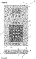
- the system comprises an assay plate 1 formed from three parts that nest together to form the plate body, namely a first (upper) plate part 2 illustrated in Figures 1 to 6 , a second plate part 3 illustrated in Figures 7A to 7C , and a base plate part 4 illustrated in Figures 8A to 8C .
- the provision of wells in the second plate part allows the second plate part to be disposable, allowing re-use of the first plate part which does not come into direct contact with the cell culture model that is being assayed.
- Figure 9 illustrated the assembled plate body.
- Figure 10 illustrates the first fluid control module disposed over the assay wells in the plate
- Figure 11 illustrates an assay fluid recirculation system comprising the first fluid control module disposed over the assay wells disposed in the first recess and a second fluid control module disposed over fluid pumping wells disposed in a second recess in the plate
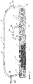
- Figure 12 illustrates one full fluidic circuit comprising a fluidic conduit and fluid recirculation conduit, and a fluid inlet and fluid outlet. It will be appreciated that the plate body does not need to be formed in separate parts but may be formed from a single plate body.
- the first plate part 2 is described and comprises a planar plate having a top surface 5, lower surface 6, end walls 7 and sidewalls 8.
- the top surface 5 has a first recessed section 10 and a second recessed section 11.
- the first recessed section 10 comprises three first fluidic conduits 12 (Y-conduits) and three second fluidic conduits 13 (X-conduits) that intersect at through apertures 14.
- the apertures receive wells provided on a second plate part as described below during assembly of the plate such that the top of the wells is provided on the same plane as the fluidic conduits.
- the first recessed section has nine wells arranged in a 3 x 3 grid array.
- the fluidic conduits are defined along part of their length by elongated grooves formed in the top surface of the first recessed section 10 and a silicone layer 15 (not visible) that covers the top of the recess, fluidically sealing the recess and forming an upper surface of the fluidic conduits. In this manner, the fluidic conduits can be deformed and pinched closed using pins of a fluid control module as described in more detail below.
- Each of the first fluidic conduits 12 has a fluid inlet 20 on the top of the plate, a first section 21 disposed in the first recessed section 10, an outlet 22 on the top of the plate, an inlet 23 on the top of the plate, a second section 24 disposed in the second recessed section 11, and a fluid outlet 19 disposed in the end wall 7 (See Figure 6 ).
- the first 21 section of the fluidic conduit provides fluidic communication to a column of three wells (disposed in the apertures 14 when the plate is assembled, as illustrated in Figure 9 ) in series and includes a first depression 25A disposed between the first and second apertures and a second depression 25B disposed between second and third apertures.
- a section of the first recessed section 10 of the plate is illustrated showing a first fluidic conduit 12 intersecting with a second fluidic conduit 13 at a well-receiving aperture 14 and a depression 25A disposed between the first and second wells in the column of wells.
- the depression 25A has a width and depth greater than the width and depth of the fluidic conduits allowing a pin forming part of a fluid control module to press the overlying silicone layer into the depression to close the first fluidic conduit (as described in more detail below).
- the second section 24 of the first fluidic conduits 12 is provided in the second recessed section 11 and defined by an elongated groove and a second silicone layer 30 that covers the top of the recess 11, fluidically sealing the recess and forming an upper surface of the second section of the fluidic conduits.
- the second section 24 also includes a fluid pumping well 31 that in use receives a pin forming part of a second fluid control module to press the overlying silicone layer into the well to pump fluid in a circuit around the plate.
- Each of the three second fluidic conduits 13 (X-conduits) comprises a fluid inlet 32 disposed in a sidewall 8 of the plate, a fluid outlet (not shown) disposed in an opposite sidewall of the plate, and a central section disposed in the recessed section of the plate 10 (defined as described for the first fluidic conduit by an elongated groove and cover of silicone) that provides fluidic communication to a column of three wells (disposed in the apertures 14 when the plate is assembled, as illustrated in Figure 9 ) in series.
- Each of the second fluidic conduits 13 includes a first depression 25C disposed between the first and second apertures in the row and a second depression 25D disposed between second and third apertures in the row.
- the lower surface of the plate comprises a stepped recess 35 dimensioned to receive the second plate part 3 and base plate part 4.
- the assembled plate with the second plate part 3 and base plate part 4 nested in the recess 35 is illustrated in Figure 9 .
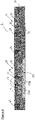
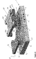
- the second plate part 3 has a rectangular planar plate body comprising a first plate section 35 formed of acrylic and a lower well imaging section 36 formed of light transparent and gas diffusing PDMS.
- a first plate section 35 formed of acrylic
- a lower well imaging section 36 formed of light transparent and gas diffusing PDMS.
- Nine wells 37 are provided each having an upper well section 38 projecting proud of the top surface of the plate and a lower well section 41 formed in the plate.
- Each well has a depth of about 6.75 mm with an open top 39 having a diameter of about 2.89 mm and a concave base 40 having a diameter across the top of the concave part of about 2.04 mm.
- the sidewalls of each well 37 are defined by the first plate section 35.
- the PDMS well imaging section 36 has a planar base and a plurality of frustoconical sections 43 that extend upwardly with inwardly tapering sidewalls from the planar base to form the concave base 40 of the wells.
- the base plate has apertures 45 in the base that are aligned with the frustoconical PDMS sections 36 to allow the wells to be viewed with an imaging device (not shown) disposed underneath the plate assembly 1.
- the PDMS also allows for gas diffusion into the wells.
- the base plate 4 is illustrated and comprises a planar rectangular plate having a top part 51, bottom part 52, stepped sidewall 53, and nine apertures 45 extending through the plate from the top surface to the bottom surface.
- the top part 51 is dimensioned to align with the base of the second plate part 3 when the second plate part and base plate part are coupled together.
- the bottom part comprises holes 55 to receive fixing screws for fixing the base plate part 4 in the recess 35 of the first plate part 2.
- an assay plate system according to one embodiment of the invention is illustrated in which parts described with reference to the previous embodiments are assigned the same reference numerals.
- the system comprises an assay plate 1 as described with reference to Figures 1 to 9 , a first fluid control module 60 positioned above the 3 x 3 grid array of wells 37 disposed in the first recessed section 10 of the plate, and a second fluid control module 61 positioned above the second recessed section 11 of the plate.
- the actuation system for the fluid control modules is removed for clarity.
- the first fluid control module 60 comprises a first set of pins 62 attached to a first plate 63 having a plurality of apertures 64, and a second set of pins 65 that are longer than the first set of pins attached to a second plate 66 disposed above the first plate 63, with the second set of pins projecting through the apertures of the first plate 63.
- the second fluid control module 61 comprises three pins 67 attached to a third plate 68.
- the first set pins 62 are positioned over the depressions 25A, 25B in the first fluidic conduits 12 and the second set of pins 65 are positioned over the depressions 25C, 25D in the second fluidic conduits 13.
- a plate actuation means (illustrated in Figures 11 and 12 ) is operatively coupled to each plate and configured to move each plate independently towards the top of the assay plate 1.
- the second plate 66 When the second plate 66 is moved towards the assay plate 1 and the first plate 63 is not moved, the second set of pins 65 are depressed pushing the silicone cover into the depression 25C, 25D in the second fluidic conduits 13 closing those conduits and preventing assay fluid moving across the rows of wells of the plate in a X-direction, with the result that flow of assay fluid is channelled across the columns of wells via the first fluidic conduits 12 in a Y-direction.
- the first plate 63 is moved towards the assay plate 1 and the second plate 66 is not moved, the first set of pins 62 are depressed pushing the silicone cover into the depressions 25A, 25B of closing the first fluidic conduits 12 and preventing assay fluid moving across the wells of the plate in a Y-direction, with the result that flow of assay fluid is channelled across the column of wells via the X-direction conduits.
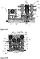
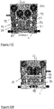
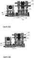
- FIGS 11A to 11C and 12A to 12C illustrate the actuation system for the first fluid control module 60 and second fluid control module 61 in more detail.
- the actuation system for the first fluid control module 60 comprises a frame 70 having a base plate 71 with apertures, upright supporting arms 72 and four axles 73 mounted between the arms. Each axle supports an eccentrically mounted camwheel 74.
- the first plate 63 is mounted to the arms 72 which are received by apertures 76A to allow vertical sliding movement on the plate of the arms and is spaced apart from the base plate 72 by first springs 75.
- the second plate 66 is similarly mounted to the arms received in apertures 76B for vertical sliding movement and spaced apart from the base plate 72 by second springs 77. The springs bias the plates away from the assay plate 1.
- the camwheels 74A and 74B are operably connected to the second plate 66 by cam followers 78 so that when the cam wheels rotate the second plate is urged downwardly pushing the second set of pins 65 into engagement with the silicone cover and fluidic conduits as illustrated in Figure 11C and 12C .
- the camwheels 74C and 74D are operably connected to the first plate 63 by cam followers 79 so that when the cam wheels rotate the first plate is urged downwardly pushing the first set of pins 62 into engagement with the silicone cover and fluidic conduits as illustrated in Figure 11B and 12B .
- the springs and cam followers are not illustrated second fluid control module 61 is of broadly the same construction as the first fluid control module.
- One first fluidic conduit is illustrated and comprises a fluid inlet 20 on the top of the plate, a first section 21 disposed in the first recessed section 10, an outlet 22 on the top of the plate, an inlet 23 on the top of the plate, a second section 24 disposed in the second recessed section 11, and a fluid outlet 19 disposed in the end wall 7 (See Figure 6 ).
- An external conduit 80 having a pressure activated one-way valve 82 is shown fluidically connecting the outlet 22 and inlet 23.
- An assay fluid supply conduit 84 provides fluid from a fluid reservoir (not shown) to an inlet divert valve 85, which is operable to fluidically connect the fluid supply conduit 84 with the fluid inlet 20 (to supply assay fluid to the plate) or to fluidically connect the fluid inlet 20 with a fluid recirculation conduit 86 to receive assay fluid that is being recirculated from the fluid outlet 19.
- the fluid recirculation conduit 86 also includes a pressure activated one-way valve 87.
- a second divert valve 88 is provided and operable to direct the assay fluid to waste or to the recirculation conduit.
- the sequential operation of the fluid control modules works to recirculate assay fluid across the wells via the first fluidic conduits.
- a first step the pins of the second fluid control module are depressed into engagement with the pumping wells of the second recessed section of the plate, and the pins of the first fluid control module are spaced from the plate, as shown in Figure 10 . Due to the presence of the one-way valve 82 the assay fluid is forced into the fluid recirculation conduit 86 where it passes through the second pressure activated one-way valve 87.
- the pins of the second fluid control module are retracted while the pins of the first fluid control module are depressed.
- the first plate section 35 is formed by machining or casting, a mould 90 having nine well-shaped projections 91 is attached to the first plate section 35 with the projections 91 inserted into the open tops 39 of the wells 37.
- the first plate section 35 is then inverted and PDMS is added into the recess in the base of first plate section 35 (the recess can be seen in Figure 7B ) where it fills the recess.
- the PDMS is then cured in an oven and forms the well imaging section 36 of the plate (light transparent and gas permeable) comprising the base 40 of each of the wells, plurality of frustoconical PDMS sections 43, and planar base 44.
- the base plate 4 is then attached to the second plate with the apertures 45 in register with the base of the wells which are viewable through the PDMS well imaging section.
Landscapes
- Health & Medical Sciences (AREA)
- Chemical & Material Sciences (AREA)
- Life Sciences & Earth Sciences (AREA)
- Engineering & Computer Science (AREA)
- Wood Science & Technology (AREA)
- Zoology (AREA)
- Organic Chemistry (AREA)
- Bioinformatics & Cheminformatics (AREA)
- Biotechnology (AREA)
- Genetics & Genomics (AREA)
- General Engineering & Computer Science (AREA)
- Biochemistry (AREA)
- Sustainable Development (AREA)
- General Health & Medical Sciences (AREA)
- Microbiology (AREA)
- Biomedical Technology (AREA)
- Clinical Laboratory Science (AREA)
- Analytical Chemistry (AREA)
- General Chemical & Material Sciences (AREA)
- Molecular Biology (AREA)
- Physiology (AREA)
- Cell Biology (AREA)
- Apparatus Associated With Microorganisms And Enzymes (AREA)
Priority Applications (1)
| Application Number | Priority Date | Filing Date | Title |
|---|---|---|---|
| EP21185836.0A EP4119652A1 (fr) | 2021-07-15 | 2021-07-15 | Ensemble plaque de dosage d'un modèle de culture cellulaire |
Applications Claiming Priority (1)
| Application Number | Priority Date | Filing Date | Title |
|---|---|---|---|
| EP21185836.0A EP4119652A1 (fr) | 2021-07-15 | 2021-07-15 | Ensemble plaque de dosage d'un modèle de culture cellulaire |
Publications (1)
| Publication Number | Publication Date |
|---|---|
| EP4119652A1 true EP4119652A1 (fr) | 2023-01-18 |
Family
ID=76942898
Family Applications (1)
| Application Number | Title | Priority Date | Filing Date |
|---|---|---|---|
| EP21185836.0A Withdrawn EP4119652A1 (fr) | 2021-07-15 | 2021-07-15 | Ensemble plaque de dosage d'un modèle de culture cellulaire |
Country Status (1)
| Country | Link |
|---|---|
| EP (1) | EP4119652A1 (fr) |
Citations (4)
| Publication number | Priority date | Publication date | Assignee | Title |
|---|---|---|---|---|
| US20070051412A1 (en) * | 2005-09-02 | 2007-03-08 | Heath James R | Method and apparatus for the mechanical actuation of valves in fluidic devices |
| US20120231976A1 (en) * | 2011-03-08 | 2012-09-13 | Chang Gung University | Microfluidic Chip for High-Throughput Perfusion-Based Three-Dimensional Cell Culture |
| US20140212964A1 (en) * | 2013-01-29 | 2014-07-31 | The Massachusetts Institute Of Technology | Modular platform for multi-tissue integrated cell culture |
| WO2020081740A1 (fr) * | 2018-10-17 | 2020-04-23 | Northwestern University | Plateforme de culture tissulaire ayant de multiples chambres de puits en raccordement fluidique par l'intermédiaire de canaux microfluidiques et de vannes de sélection |
-
2021
- 2021-07-15 EP EP21185836.0A patent/EP4119652A1/fr not_active Withdrawn
Patent Citations (4)
| Publication number | Priority date | Publication date | Assignee | Title |
|---|---|---|---|---|
| US20070051412A1 (en) * | 2005-09-02 | 2007-03-08 | Heath James R | Method and apparatus for the mechanical actuation of valves in fluidic devices |
| US20120231976A1 (en) * | 2011-03-08 | 2012-09-13 | Chang Gung University | Microfluidic Chip for High-Throughput Perfusion-Based Three-Dimensional Cell Culture |
| US20140212964A1 (en) * | 2013-01-29 | 2014-07-31 | The Massachusetts Institute Of Technology | Modular platform for multi-tissue integrated cell culture |
| WO2020081740A1 (fr) * | 2018-10-17 | 2020-04-23 | Northwestern University | Plateforme de culture tissulaire ayant de multiples chambres de puits en raccordement fluidique par l'intermédiaire de canaux microfluidiques et de vannes de sélection |
Similar Documents
| Publication | Publication Date | Title |
|---|---|---|
| US11680241B2 (en) | Perfusion enabled bioreactors | |
| Zheng et al. | Organ‐on‐a‐chip systems: microengineering to biomimic living systems | |
| US10843189B2 (en) | Methods and apparatus for cell culture array | |
| CA2964422C (fr) | Dispositif microfluidique pour dosages a base de cellules | |
| CN103981096B (zh) | 一种两层细胞培养体系器官芯片及其制备方法 | |
| RU2668157C1 (ru) | Устройство для формирования двухслойной клеточной модели | |
| US20070048727A1 (en) | Biliary barrier | |
| CN107257850A (zh) | 用于哺乳动物细胞的高通量聚集和操作的装置 | |
| EP1891201A2 (fr) | Systeme de culture pharmacocinetique presentant des barrieres biologiques | |
| Farshidfar et al. | The feasible application of microfluidic tissue/organ-on-a-chip as an impersonator of oral tissues and organs: a direction for future research | |
| CN119432597B (zh) | 基于印章微结构图案化的血管化类器官芯片及其制备方法 | |
| Cui et al. | Pulsed microfluid force-based on-chip modular fabrication for liver lobule-like 3D cellular models | |
| JP2024500268A (ja) | 高スループットマイクロウェルアレイプレートおよび製造方法 | |
| CN202576429U (zh) | 一种微流扩散和开放介入的细胞培养阵列芯片 | |
| Mai et al. | MatriGrid® based biological morphologies: Tools for 3D cell culturing | |
| US20260022316A1 (en) | An assay plate system to assay a cell culture model | |
| CN117721019A (zh) | 一种血管化器官芯片及其应用 | |
| EP4119652A1 (fr) | Ensemble plaque de dosage d'un modèle de culture cellulaire | |
| EP4119226A1 (fr) | Système de plaque de dosage pour un modèle de culture cellulaire | |
| EP3746541B1 (fr) | Dispositifs et procédés de croissance tridimensionnelle de cellules | |
| Ahmed et al. | Optimization of the performance of high-brightness electron guns | |
| CN120682933A (zh) | 一种高通量类器官培养液芯器件 | |
| US20260109925A1 (en) | Microfluidic device for forming three-dimensional tissue barrier | |
| CN222411621U (zh) | 一种类器官培养装置和动态流体类器官培养体系 | |
| CN221501120U (zh) | 一种用于不同种类的类器官联合培养的装置 |
Legal Events
| Date | Code | Title | Description |
|---|---|---|---|
| PUAI | Public reference made under article 153(3) epc to a published international application that has entered the european phase |
Free format text: ORIGINAL CODE: 0009012 |
|
| STAA | Information on the status of an ep patent application or granted ep patent |
Free format text: STATUS: THE APPLICATION HAS BEEN PUBLISHED |
|
| AK | Designated contracting states |
Kind code of ref document: A1 Designated state(s): AL AT BE BG CH CY CZ DE DK EE ES FI FR GB GR HR HU IE IS IT LI LT LU LV MC MK MT NL NO PL PT RO RS SE SI SK SM TR |
|
| STAA | Information on the status of an ep patent application or granted ep patent |
Free format text: STATUS: THE APPLICATION HAS BEEN WITHDRAWN |
|
| 18W | Application withdrawn |
Effective date: 20230717 |