EP4119761B1 - Portail à enroulement rapide - Google Patents
Portail à enroulement rapide Download PDFInfo
- Publication number
- EP4119761B1 EP4119761B1 EP21185668.7A EP21185668A EP4119761B1 EP 4119761 B1 EP4119761 B1 EP 4119761B1 EP 21185668 A EP21185668 A EP 21185668A EP 4119761 B1 EP4119761 B1 EP 4119761B1
- Authority
- EP
- European Patent Office
- Prior art keywords
- curtain
- quick
- frame
- accordance
- roller door
- Prior art date
- Legal status (The legal status is an assumption and is not a legal conclusion. Google has not performed a legal analysis and makes no representation as to the accuracy of the status listed.)
- Active
Links
Images

Classifications
-
- E—FIXED CONSTRUCTIONS
- E06—DOORS, WINDOWS, SHUTTERS, OR ROLLER BLINDS IN GENERAL; LADDERS
- E06B—FIXED OR MOVABLE CLOSURES FOR OPENINGS IN BUILDINGS, VEHICLES, FENCES OR LIKE ENCLOSURES IN GENERAL, e.g. DOORS, WINDOWS, BLINDS, GATES
- E06B9/00—Screening or protective devices for wall or similar openings, with or without operating or securing mechanisms; Closures of similar construction
- E06B9/02—Shutters, movable grilles, or other safety closing devices, e.g. against burglary
- E06B9/08—Roll-type closures
- E06B9/11—Roller shutters
- E06B9/17—Parts or details of roller shutters, e.g. suspension devices, shutter boxes, wicket doors, ventilation openings
- E06B9/171—Rollers therefor; Fastening roller shutters to rollers
-
- E—FIXED CONSTRUCTIONS
- E06—DOORS, WINDOWS, SHUTTERS, OR ROLLER BLINDS IN GENERAL; LADDERS
- E06B—FIXED OR MOVABLE CLOSURES FOR OPENINGS IN BUILDINGS, VEHICLES, FENCES OR LIKE ENCLOSURES IN GENERAL, e.g. DOORS, WINDOWS, BLINDS, GATES
- E06B9/00—Screening or protective devices for wall or similar openings, with or without operating or securing mechanisms; Closures of similar construction
- E06B9/02—Shutters, movable grilles, or other safety closing devices, e.g. against burglary
- E06B9/08—Roll-type closures
- E06B9/11—Roller shutters
- E06B9/13—Roller shutters with closing members of one piece, e.g. of corrugated sheet metal
-
- E—FIXED CONSTRUCTIONS
- E06—DOORS, WINDOWS, SHUTTERS, OR ROLLER BLINDS IN GENERAL; LADDERS
- E06B—FIXED OR MOVABLE CLOSURES FOR OPENINGS IN BUILDINGS, VEHICLES, FENCES OR LIKE ENCLOSURES IN GENERAL, e.g. DOORS, WINDOWS, BLINDS, GATES
- E06B9/00—Screening or protective devices for wall or similar openings, with or without operating or securing mechanisms; Closures of similar construction
- E06B9/02—Shutters, movable grilles, or other safety closing devices, e.g. against burglary
- E06B9/08—Roll-type closures
- E06B9/11—Roller shutters
- E06B9/17—Parts or details of roller shutters, e.g. suspension devices, shutter boxes, wicket doors, ventilation openings
- E06B9/17076—Sealing or antirattling arrangements
-
- E—FIXED CONSTRUCTIONS
- E06—DOORS, WINDOWS, SHUTTERS, OR ROLLER BLINDS IN GENERAL; LADDERS
- E06B—FIXED OR MOVABLE CLOSURES FOR OPENINGS IN BUILDINGS, VEHICLES, FENCES OR LIKE ENCLOSURES IN GENERAL, e.g. DOORS, WINDOWS, BLINDS, GATES
- E06B9/00—Screening or protective devices for wall or similar openings, with or without operating or securing mechanisms; Closures of similar construction
- E06B9/56—Operating, guiding or securing devices or arrangements for roll-type closures; Spring drums; Tape drums; Counterweighting arrangements therefor
- E06B9/58—Guiding devices
- E06B9/582—Means to increase gliss, light, sound or thermal insulation
-
- E—FIXED CONSTRUCTIONS
- E06—DOORS, WINDOWS, SHUTTERS, OR ROLLER BLINDS IN GENERAL; LADDERS
- E06B—FIXED OR MOVABLE CLOSURES FOR OPENINGS IN BUILDINGS, VEHICLES, FENCES OR LIKE ENCLOSURES IN GENERAL, e.g. DOORS, WINDOWS, BLINDS, GATES
- E06B9/00—Screening or protective devices for wall or similar openings, with or without operating or securing mechanisms; Closures of similar construction
- E06B9/56—Operating, guiding or securing devices or arrangements for roll-type closures; Spring drums; Tape drums; Counterweighting arrangements therefor
- E06B9/78—Operating, guiding or securing devices or arrangements for roll-type closures; Spring drums; Tape drums; Counterweighting arrangements therefor for direct manual operation, e.g. by tassels, by handles
Definitions
- the invention relates to a high-speed roller door, in particular a high-speed roller door for cold storage rooms.
- Such doors with a vertical running direction of the door leaf are known in numerous design variants. Reference is made in this context to EP 1 760 237 A2 , EP 0 816 624 B1 or EP 1 847 673 A1 referred to.
- the invention is based on a state of the art as it is known from WO 2016/119836 A1
- This design has proven extremely successful; due to the comparatively light and flexible door leaf, high opening and closing speeds can be achieved, which is particularly advantageous for closing cold rooms and freezer rooms, which on the one hand must ensure good accessibility, but on the other hand should only be open for as short a time as possible due to the temperature differences between the interior of the room and the surrounding area. Not only the time the door is open counts, but also the time in which the door opens and closes again. During this time, access is not guaranteed, but the heat exchange that is to be avoided is still there. It is therefore a constant goal to keep opening and closing times as short as possible, which in practice is only achievable with high-speed roller doors, which have a comparatively low dead weight and whose flexible door leaf can be wound up with a vertical running direction.
- WO 2013/167379 A1 discloses a lifting gate assembly with a lintel sealing device.
- the lintel sealing device has a free movement gap through which the gate leaf can move.
- the lintel sealing device has a pivoting part so that the gap can widen when the closing plate enters.
- the lifting gate is intended for sealing a clean room, with the door leaf being pressed against the slide rails of the door leaf by the excess pressure of the clean room, so that the door is sealed when closed.
- the invention is based on the object of designing a high-speed roller door, in particular a high-speed cold room roller door of the type mentioned at the outset, with structurally simple but reliable means in such a way that, on the one hand, rapid opening and closing is possible, but, on the other hand, a tight closure can also be ensured when the door is closed.
- the object of the invention is to design a high-speed roller door, in particular a high-speed cold storage roller door, with structurally simple but reliable means in such a way that, on the one hand, rapid opening and closing is possible, but, on the other hand, a tight closure when closed Gate can be ensured without having to put the space to be sealed under overpressure.
- the high-speed roller door according to the invention which is particularly a high-speed cold storage roller door, comprises a curtain that can be wound around a horizontal shaft, a winding drive, and a pressure frame.
- the pressure frame applies force to the curtain in its position closing the door opening, transverse to the flat side, for tight contact with the door frame.
- control means are provided on the curtain side, which space the pressure frame from the curtain when the roller door is opened.
- the basic idea of the solution according to the invention is to space the pressure frame from the curtain by means of control means arranged on the curtain side, preferably by means of mechanically effective control means, as soon as the roller door opens. This eliminates the need for a separate drive for the pressure frame.
- the winding drive thus Not only is the roller shutter's curtain wound up, but the pressure frame is also controlled simultaneously.
- the "curtain” refers to the door leaf, which in the case of roller doors is also referred to as the “curtain.”
- This curtain is flexible, allowing it to be wound up and preferably has a specific weight of less than 0.5 kg/ dm3 . It has a certain inherent stability, allowing it to withstand both tensile forces during winding and shear forces during unwinding, meaning it cannot be unwound solely under its own weight.
- the frames can advantageously be designed to be closed; however, in this case the lower cross connection on the floor side must be installed in such a way that it can be driven over. As a rule, however, it is sufficient to design the frames in such a way that they guide the curtain on its long sides and extend vertically there, with each frame having at least one upper cross beam connecting the vertical sides. These connecting upper cross beams then ensure the necessary stability of the frames.
- the control means provided on the curtain side can advantageously be formed by one or more wedge-shaped control bodies which are designed and arranged in a wedge-shaped manner in the opening direction, i.e. with a cross-section reducing design, so that when the curtain is wound up, i.e. when the curtain is raised, they come into contact with the upper cross beam of the pressure frame or with a control beam connected to it and space this at least from the cross beam of the stationary frame.
- such a wedge-shaped control body can be arranged on one side of the curtain, on the other side of the curtain, or on both sides of the curtain; the latter is particularly advantageous for force distribution.
- one wedge-shaped control body on one side of the curtain is sufficient, but it is particularly advantageous to have two or more wedge-shaped control bodies should be arranged horizontally next to each other and preferably on both flat sides of the curtain.
- an abutment bar should be provided on the other side of the curtain at the top of the stationary frame so that the curtain does not deflect in the area of the wedge-shaped control bodies when raised, but rather generates the necessary transverse forces to space the pressure frame.
- Both the abutment bar and the control bar are advantageously designed as abutment roller or control roller. These do not necessarily have to be rotatably mounted; a tubular design of the bars may suffice.
- the high-speed roller door is provided with a locking device that holds the pressure frame in this position after the separation.
- a locking device can be arranged at a suitable location between the frames or next to the frames.
- Such a locking device is advantageously designed to be self-locking, specifically in such a way that it is activated and/or deactivated by control means arranged on the curtain side. If such a locking device is designed to be self-locking, it is sufficient to activate it once to move it into the locked position, and vice versa, only once to move it out of the locked position. This is advantageously achieved by appropriate spring means.
- control means for the locking device arranged on the side of the curtain have a curtain have a control rod protruding from the door opening, which is operatively connected to a locking lever which is pivotably arranged on the frame side and which, in a first position, holds the pressure frame in its spaced-apart position and, in a second position, releases its movement.
- the locking lever so that it pivots automatically into its locked position.
- the control rod or rods protruding laterally on both sides of the curtain serve to deactivate the locking device, i.e. to pivot the spring-loaded locking lever out of its locked position and to hold it in this position. This is the position in which the curtain closes the door opening and in which the pressure frame presses the curtain sealingly against the stationary frame.
- the curtain itself is advantageously made of a flexurally elastic composite material based on textiles, which is lightweight, has good heat insulation and is inherently stable, so that it can be wound up onto a shaft, but on the other hand is so inherently stable that a certain thrust force can be exerted on it when unwinding, so that it can be moved at high speed in both the opening and closing directions.
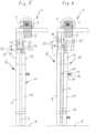
- the high-speed cold room roller door 1 shown in the drawings has a curtain closing a door opening 2 of a cold room 3, which is designed as a textile-based composite material that is elastic and flexible, so that it can be wound up on a shaft 4 above the door opening 2, which can be driven by a winding drive 5, not shown in detail here, to open or close the roller door.
- the roller shutter has a fixed frame 6, which is firmly and tightly connected to the masonry in front of the door opening 2.
- the frame 6 has two vertical beams 7 extending from the floor 8 to an upper crossbeam 9, which connects the free upper ends of the vertical beams 7.
- a pressure frame 10 Parallel to the frame 6 and at a distance from it, a pressure frame 10 is provided, which also has two vertical beams 11 that are connected to one another at their upper ends by an upper cross beam 12.
- the pressure frame 10 is mounted for limited movement via two guide bolts 13 so that the pressure frame 10 can be moved towards the frame 6 and in the opposite direction.
- Four clamping bolts 14 are provided, which are anchored in the vertical beams 7 of the fixed frame 6 and which are guided through correspondingly aligned holes in the vertical beams 11 of the pressure frame 10. These are provided at their ends with helical compression springs 15, which are clamped between the outside of the pressure frame 10 and washers 16. The washers 16 are secured by nuts 17 at the end of the clamping bolts 14.
- a distance from the fixed cross beam 12 is provided by means of supports 26 attached to the sides of the fixed frame 6.
- Frame horizontally and transversely running support beam 27 is attached, which carries three in this design three helical compression springs 28, with which a pressing force is exerted on the upper cross beam 12 of the pressure frame 10 in order to ensure a tight closure of the curtain 3 not only laterally but also in the upper area of the door opening.
- clamping bolts 14 can also be formed by clamping screws which are fixed in corresponding threaded holes of the frame 6 and whose heads hold the washers 16.
- the vertical beams 7 and 11 of the frames 6 and 10 serve to guide the curtain laterally during opening and closing. Furthermore, the frame 6 forms an abutment against which the curtain 3, in its position closing the door opening 2, is pressed by the spring force of the coil springs 15 via the pressure frame 10, thus sealing the door opening 2 when the curtain 3 is closed. This sealing position is shown in the Fig. 2 and 5 shown.
- control means are provided on the curtain 3, which move the pressure frame 10 from the Fig. 2 and 5 shown sealing position so that the Fig. 3 and 6 shown spaced position is reached, in which the curtain 3 is guided between the frames 6 and 10, but otherwise is practically freely movable.
- wedge-shaped control bodies 18 are provided on both flat sides of the curtain 3.
- the control bodies 8 are wedge-shaped in the winding direction, i.e. with an effective cross-section increasing from top to bottom.
- control bodies 18, distributed along a horizontal line of the curtain 3, are operatively connected to an abutment beam 19 in the form of a roller on the rear side of the curtain 3, which is firmly connected to the frame 6.
- the control bodies 18 on the front side of the curtain 3 are operatively connected to a control beam 20 in the form of a control roller, which is firmly connected to the upper side of the pressure frame 10 via levers 21.
Landscapes
- Engineering & Computer Science (AREA)
- Structural Engineering (AREA)
- Architecture (AREA)
- Civil Engineering (AREA)
- Power-Operated Mechanisms For Wings (AREA)
- Operating, Guiding And Securing Of Roll- Type Closing Members (AREA)
- Specific Sealing Or Ventilating Devices For Doors And Windows (AREA)
Claims (13)
- Porte à enroulement rapide, notamment porte à enroulement rapide pour chambre froide, pourvue d'un tablier (3) enroulable autour d'un arbre (4) horizontal, pourvue d'un entraînement enrouleur (5) et pourvue d'un cadre de pression (10), lequel contraint le tablier (3) par une force à la transversale de la face plane du tablier (3) dans sa position assurant la fermeture pour l'appui étanche sur un cadre de porte, caractérisée en ce que du côté tablier sont prévus des moyens de commande (18) lesquels, lors de l'ouverture de la porte à enroulement (1) écartent le cadre de pression (10) du tablier (3).
- Porte à enroulement rapide selon la revendication 1, caractérisée en ce que le tablier (3) est guidé entre un cadre (6) stationnaire et le cadre de pression (10), le cadre de pression (10) étant fixé en déplacement limité sur le cadre (6) et étant contraint par la force d'un ressort en direction de celui-ci.
- Porte à enroulement rapide selon la revendication 1 ou 2, caractérisée en ce que les cadres (6, 10) guident le tablier (3) sur ses côtés longitudinaux et s'y étendent à la verticale et en ce que chaque cadre (6, 10) comporte au moins un montant transversal (9, 12) supérieur reliant les côtés verticaux.
- Porte à enroulement rapide selon l'une quelconque des revendications précédentes, caractérisée en ce que du côté tablier est prévu au moins un organe de commande (18) cunéiforme dans la direction d'ouverture, lequel lors de la montée du tablier (3) entre en contact avec le montant transversal (12) supérieur du cadre de pression (10) ou avec un montant de commande (20) relié avec celui-ci et écarte celui-ci au moins par rapport au montant transversal (9) du cadre (6) stationnaire.
- Porte à enroulement rapide selon l'une quelconque des revendications précédentes, caractérisée en ce que du côté tablier, deux organes de commande (18) cunéiformes ou plus sont placés côte à côte à l'horizontale et en ce que sur le cadre (6) stationnaire est placé vers le haut avec un écart par rapport au montant transversal (9) supérieur un montant de contre-appui (19), de préférence sous la forme d'un galet de contre-appui et sur le cadre de pression (10) est placé vers le haut avec un écart par rapport au montant transversal (12) supérieur le montant de commande (20), de préférence sous la forme d'un galet de commande.
- Porte à enroulement rapide selon l'une quelconque des revendications précédentes, caractérisée en ce qu'il est prévu un dispositif de blocage (22) lequel maintient avec un écart le cadre d'appui (10) après l'écartement.
- Porte à enroulement rapide selon l'une quelconque des revendications précédentes, caractérisée en ce que le dispositif de blocage (22) est conçu de manière autobloquante et s'active et / ou se désactive à l'aide de moyens de commande (25) placés du côté tablier.
- Porte à enroulement rapide selon l'une quelconque des revendications précédentes, caractérisée en ce que les moyens de commande placés du côté du tablier comportent une barre de commande (25) débordant latéralement du tablier pour le dispositif de blocage (22), laquelle est en liaison active avec un levier de blocage (23) placé de manière pivotante sur le côté du cadre, lequel dans une première position maintient le cadre de pression (10) dans sa position écartée et le libère dans sa deuxième position.
- Porte à enroulement rapide selon l'une quelconque des revendications précédentes, caractérisée en ce que le levier de blocage (23) est contraint par ressort de sorte à pivoter automatiquement dans sa position de blocage.
- Porte rapide selon l'une quelconque des revendications précédentes, caractérisée en ce que vers les deux côtés du tablier (3) est prévu chaque fois un dispositif de blocage (22) et en ce que du côté tablier, des barres de commande (25) débordent latéralement.
- Porte à enroulement rapide selon l'une quelconque des revendications précédentes, caractérisée en ce que la barre de commande / les barres de commande (25) est / sont partie intégrante d'une barre transversale, laquelle s'étend sur toute la largeur du tablier (3).
- Porte à enroulement rapide selon l'une quelconque des revendications précédentes, caractérisée en ce que les organe de commande (18) sont fixés sur la barre transversale.
- Porte à enroulement rapide selon l'une quelconque des revendications précédentes, caractérisée en ce que le tablier (3) est conçu dans une matière composite élastique en flexion sur base textile.
Priority Applications (3)
| Application Number | Priority Date | Filing Date | Title |
|---|---|---|---|
| EP21185668.7A EP4119761B1 (fr) | 2021-07-14 | 2021-07-14 | Portail à enroulement rapide |
| EP22178193.3A EP4119760B1 (fr) | 2021-07-14 | 2022-06-09 | Portail à enroulement rapide |
| US17/863,573 US12410656B2 (en) | 2021-07-14 | 2022-07-13 | Quick-action roll-up door |
Applications Claiming Priority (1)
| Application Number | Priority Date | Filing Date | Title |
|---|---|---|---|
| EP21185668.7A EP4119761B1 (fr) | 2021-07-14 | 2021-07-14 | Portail à enroulement rapide |
Publications (3)
| Publication Number | Publication Date |
|---|---|
| EP4119761A1 EP4119761A1 (fr) | 2023-01-18 |
| EP4119761C0 EP4119761C0 (fr) | 2025-07-09 |
| EP4119761B1 true EP4119761B1 (fr) | 2025-07-09 |
Family
ID=76942809
Family Applications (2)
| Application Number | Title | Priority Date | Filing Date |
|---|---|---|---|
| EP21185668.7A Active EP4119761B1 (fr) | 2021-07-14 | 2021-07-14 | Portail à enroulement rapide |
| EP22178193.3A Active EP4119760B1 (fr) | 2021-07-14 | 2022-06-09 | Portail à enroulement rapide |
Family Applications After (1)
| Application Number | Title | Priority Date | Filing Date |
|---|---|---|---|
| EP22178193.3A Active EP4119760B1 (fr) | 2021-07-14 | 2022-06-09 | Portail à enroulement rapide |
Country Status (2)
| Country | Link |
|---|---|
| US (1) | US12410656B2 (fr) |
| EP (2) | EP4119761B1 (fr) |
Family Cites Families (15)
| Publication number | Priority date | Publication date | Assignee | Title |
|---|---|---|---|---|
| DE19625215C2 (de) | 1996-06-25 | 2001-05-03 | Cardo Door Continental B V | Schnellaufrolltor für Tiefkühlhäuser |
| US5752558A (en) * | 1997-06-16 | 1998-05-19 | Lin; Cheng-Tai | Tensioning device for a control cord of a blind assembly |
| US20040206462A1 (en) * | 2003-04-15 | 2004-10-21 | Innovative Product Achievements, Inc. | Reduced friction flexible door |
| NL1025507C2 (nl) * | 2004-02-17 | 2005-08-19 | Bg Door Internat V O F | Gasdichte deur. |
| DE102005061554B4 (de) | 2005-08-31 | 2011-03-10 | Hörmann Kg Dissen | Tor, insbesondere Schnelllauftor, mit Lichtschranke |
| DE102006018637B4 (de) | 2006-04-21 | 2011-05-12 | Manfred Seysen | Schnelllauftor |
| GB2452306B (en) * | 2007-08-31 | 2012-03-28 | Bid Group Ltd | Wind restraint for a roller door curtain |
| DE102011052304A1 (de) * | 2011-07-29 | 2013-01-31 | Efaflex Inzeniring D.O.O. | Hubtor mit einer beweglichen Torblattführung |
| DE102012104039A1 (de) * | 2012-05-08 | 2013-11-14 | Efaflex Inzeniring D.O.O. Ljubljana | Hubtoranordnung sowie Torsturz-Abdichteinrichtung hierfür |
| US9556672B2 (en) * | 2014-10-28 | 2017-01-31 | Rite-Hite Holding Corporation | Rolling windbars for roll-up doors |
| PL3250774T3 (pl) | 2015-01-28 | 2020-08-10 | Frinova Gmbh | Brama, zwłaszcza brama szybkobieżna |
| US10556492B2 (en) * | 2017-11-10 | 2020-02-11 | Deere & Company | Operator cab with segmented door |
| EP3763911B1 (fr) * | 2019-07-12 | 2022-06-08 | HÖRMANN KG Dissen | Dispositif de rail de guidage pour un portail roulant ou un grillage roulant |
| EP3919715B1 (fr) * | 2020-06-02 | 2024-05-01 | Frinova GmbH | Portail, en particulier un portail à enroulement rapide |
| KR102199952B1 (ko) * | 2020-10-20 | 2021-01-11 | 한국건설기술연구원 | 곡면 셔터의 횡측 가장자리 기밀형성 구조의 가이드 프레임, 및 이를 구비한 곡면 셔터 도어 |
-
2021
- 2021-07-14 EP EP21185668.7A patent/EP4119761B1/fr active Active
-
2022
- 2022-06-09 EP EP22178193.3A patent/EP4119760B1/fr active Active
- 2022-07-13 US US17/863,573 patent/US12410656B2/en active Active
Also Published As
| Publication number | Publication date |
|---|---|
| EP4119761C0 (fr) | 2025-07-09 |
| EP4119761A1 (fr) | 2023-01-18 |
| US12410656B2 (en) | 2025-09-09 |
| EP4119760C0 (fr) | 2023-12-27 |
| EP4119760B1 (fr) | 2023-12-27 |
| EP4119760A1 (fr) | 2023-01-18 |
| US20230105435A1 (en) | 2023-04-06 |
Similar Documents
| Publication | Publication Date | Title |
|---|---|---|
| DE19758648C2 (de) | Crashschutzvorrichtung für Schnellaufrolltore sowie Schnellaufrolltor | |
| EP1250509B1 (fr) | Porte relevable par sections ou porte accordeon | |
| DE4003218A1 (de) | Sektionaltor | |
| DE3508175A1 (de) | Garagentor oder hallentor mit feder-hubmechanik | |
| EP4119761B1 (fr) | Portail à enroulement rapide | |
| EP4186823B1 (fr) | Sas de transfert de marchandises | |
| CH693456A5 (de) | Ausstellvorrichtung eines Flügels, insbesondere für Fenster oder Lüftungseinrichtungen. | |
| DE102004047166B4 (de) | Sektionaltor mit Fluchttür | |
| AT521543B1 (de) | Schutzvorrichtung für Roll- und Sektionaltore | |
| EP3480407B1 (fr) | Élément coulissant vertical | |
| EP3919715B1 (fr) | Portail, en particulier un portail à enroulement rapide | |
| DE19825071C2 (de) | Parallelausstellfenster mit Drehfunktion | |
| DE2410623C3 (de) | Türanlage mit einer Mehrzahl von Pendeltürflügeln | |
| DE102016111410A1 (de) | Mittelstütze für eine Gebäudeöffnung mit großer lichter Breite | |
| EP2444583B1 (fr) | Colonne de portail pour un portail roulant | |
| DE202024101220U1 (de) | Antriebsvorrichtung mit einer Führungsschiene für einen verschiebbaren Flügel als Schiebeflügel oder verschiebbaren Hebe-Schiebeflügel eines Fensters oder einer Tür | |
| DE19713901A1 (de) | Schieberolltor zum Verschließen einer Durchgangsöffnung | |
| DE20320336U1 (de) | Rolltor mit Kollisionsschutz | |
| DE102023202379A1 (de) | Eckfenster oder Ecktür mit abstellbaren und parallel zum festen Rahmen verschiebbaren Schiebeflügeln | |
| WO2025171947A1 (fr) | Porte coulissante et procédé de fermeture d'un battant coulissant d'une porte coulissante, ledit battant coulissant étant monté mobile dans un cadre | |
| WO2001006081A1 (fr) | Cloison mobile | |
| DE1554233C (de) | Führungsbeschlag für eine Schiebetür | |
| DE4232252A1 (de) | Abhaengemechanik fuer torblaetter von sektionaltoren in geoeffneten zustand | |
| DE3430779A1 (de) | Schutzgitteranordnung | |
| EP0674080A1 (fr) | Guichet de sécurité |
Legal Events
| Date | Code | Title | Description |
|---|---|---|---|
| PUAI | Public reference made under article 153(3) epc to a published international application that has entered the european phase |
Free format text: ORIGINAL CODE: 0009012 |
|
| STAA | Information on the status of an ep patent application or granted ep patent |
Free format text: STATUS: THE APPLICATION HAS BEEN PUBLISHED |
|
| AK | Designated contracting states |
Kind code of ref document: A1 Designated state(s): AL AT BE BG CH CY CZ DE DK EE ES FI FR GB GR HR HU IE IS IT LI LT LU LV MC MK MT NL NO PL PT RO RS SE SI SK SM TR |
|
| STAA | Information on the status of an ep patent application or granted ep patent |
Free format text: STATUS: REQUEST FOR EXAMINATION WAS MADE |
|
| 17P | Request for examination filed |
Effective date: 20230712 |
|
| RBV | Designated contracting states (corrected) |
Designated state(s): AL AT BE BG CH CY CZ DE DK EE ES FI FR GB GR HR HU IE IS IT LI LT LU LV MC MK MT NL NO PL PT RO RS SE SI SK SM TR |
|
| GRAP | Despatch of communication of intention to grant a patent |
Free format text: ORIGINAL CODE: EPIDOSNIGR1 |
|
| STAA | Information on the status of an ep patent application or granted ep patent |
Free format text: STATUS: GRANT OF PATENT IS INTENDED |
|
| INTG | Intention to grant announced |
Effective date: 20250321 |
|
| GRAS | Grant fee paid |
Free format text: ORIGINAL CODE: EPIDOSNIGR3 |
|
| GRAA | (expected) grant |
Free format text: ORIGINAL CODE: 0009210 |
|
| STAA | Information on the status of an ep patent application or granted ep patent |
Free format text: STATUS: THE PATENT HAS BEEN GRANTED |
|
| AK | Designated contracting states |
Kind code of ref document: B1 Designated state(s): AL AT BE BG CH CY CZ DE DK EE ES FI FR GB GR HR HU IE IS IT LI LT LU LV MC MK MT NL NO PL PT RO RS SE SI SK SM TR |
|
| REG | Reference to a national code |
Ref country code: GB Ref legal event code: FG4D Free format text: NOT ENGLISH |
|
| REG | Reference to a national code |
Ref country code: CH Ref legal event code: EP |
|
| REG | Reference to a national code |
Ref country code: IE Ref legal event code: FG4D Free format text: LANGUAGE OF EP DOCUMENT: GERMAN |
|
| REG | Reference to a national code |
Ref country code: DE Ref legal event code: R096 Ref document number: 502021007944 Country of ref document: DE |
|
| U01 | Request for unitary effect filed |
Effective date: 20250806 |
|
| U07 | Unitary effect registered |
Designated state(s): AT BE BG DE DK EE FI FR IT LT LU LV MT NL PT RO SE SI Effective date: 20250819 |
|
| U20 | Renewal fee for the european patent with unitary effect paid |
Year of fee payment: 5 Effective date: 20250909 |
|
| PG25 | Lapsed in a contracting state [announced via postgrant information from national office to epo] |
Ref country code: IS Free format text: LAPSE BECAUSE OF FAILURE TO SUBMIT A TRANSLATION OF THE DESCRIPTION OR TO PAY THE FEE WITHIN THE PRESCRIBED TIME-LIMIT Effective date: 20251109 |
|
| PG25 | Lapsed in a contracting state [announced via postgrant information from national office to epo] |
Ref country code: NO Free format text: LAPSE BECAUSE OF FAILURE TO SUBMIT A TRANSLATION OF THE DESCRIPTION OR TO PAY THE FEE WITHIN THE PRESCRIBED TIME-LIMIT Effective date: 20251009 |
|
| PG25 | Lapsed in a contracting state [announced via postgrant information from national office to epo] |
Ref country code: HR Free format text: LAPSE BECAUSE OF FAILURE TO SUBMIT A TRANSLATION OF THE DESCRIPTION OR TO PAY THE FEE WITHIN THE PRESCRIBED TIME-LIMIT Effective date: 20250709 |
|
| PG25 | Lapsed in a contracting state [announced via postgrant information from national office to epo] |
Ref country code: GR Free format text: LAPSE BECAUSE OF FAILURE TO SUBMIT A TRANSLATION OF THE DESCRIPTION OR TO PAY THE FEE WITHIN THE PRESCRIBED TIME-LIMIT Effective date: 20251010 |
|
| PG25 | Lapsed in a contracting state [announced via postgrant information from national office to epo] |
Ref country code: PL Free format text: LAPSE BECAUSE OF FAILURE TO SUBMIT A TRANSLATION OF THE DESCRIPTION OR TO PAY THE FEE WITHIN THE PRESCRIBED TIME-LIMIT Effective date: 20250709 |
|
| PG25 | Lapsed in a contracting state [announced via postgrant information from national office to epo] |
Ref country code: RS Free format text: LAPSE BECAUSE OF FAILURE TO SUBMIT A TRANSLATION OF THE DESCRIPTION OR TO PAY THE FEE WITHIN THE PRESCRIBED TIME-LIMIT Effective date: 20251009 |
|
| PG25 | Lapsed in a contracting state [announced via postgrant information from national office to epo] |
Ref country code: ES Free format text: LAPSE BECAUSE OF FAILURE TO SUBMIT A TRANSLATION OF THE DESCRIPTION OR TO PAY THE FEE WITHIN THE PRESCRIBED TIME-LIMIT Effective date: 20250709 |
|
| REG | Reference to a national code |
Ref country code: CH Ref legal event code: H13 Free format text: ST27 STATUS EVENT CODE: U-0-0-H10-H13 (AS PROVIDED BY THE NATIONAL OFFICE) Effective date: 20260224 |
|
| PG25 | Lapsed in a contracting state [announced via postgrant information from national office to epo] |
Ref country code: SM Free format text: LAPSE BECAUSE OF FAILURE TO SUBMIT A TRANSLATION OF THE DESCRIPTION OR TO PAY THE FEE WITHIN THE PRESCRIBED TIME-LIMIT Effective date: 20250709 |
|
| PGFP | Annual fee paid to national office [announced via postgrant information from national office to epo] |
Ref country code: AT Payment date: 20260410 Year of fee payment: 5 |