EP4119773A1 - Dichtungssystem mit siliziumschicht und sperrschicht - Google Patents
Dichtungssystem mit siliziumschicht und sperrschicht Download PDFInfo
- Publication number
- EP4119773A1 EP4119773A1 EP22185191.8A EP22185191A EP4119773A1 EP 4119773 A1 EP4119773 A1 EP 4119773A1 EP 22185191 A EP22185191 A EP 22185191A EP 4119773 A1 EP4119773 A1 EP 4119773A1
- Authority
- EP
- European Patent Office
- Prior art keywords
- layer
- silicon
- barrier layer
- sub
- seal system
- Prior art date
- Legal status (The legal status is an assumption and is not a legal conclusion. Google has not performed a legal analysis and makes no representation as to the accuracy of the status listed.)
- Pending
Links
Images
Classifications
-
- F—MECHANICAL ENGINEERING; LIGHTING; HEATING; WEAPONS; BLASTING
- F02—COMBUSTION ENGINES; HOT-GAS OR COMBUSTION-PRODUCT ENGINE PLANTS
- F02C—GAS-TURBINE PLANTS; AIR INTAKES FOR JET-PROPULSION PLANTS; CONTROLLING FUEL SUPPLY IN AIR-BREATHING JET-PROPULSION PLANTS
- F02C7/00—Features, components parts, details or accessories, not provided for in, or of interest apart form groups F02C1/00 - F02C6/00; Air intakes for jet-propulsion plants
- F02C7/28—Arrangement of seals
-
- C—CHEMISTRY; METALLURGY
- C04—CEMENTS; CONCRETE; ARTIFICIAL STONE; CERAMICS; REFRACTORIES
- C04B—LIME, MAGNESIA; SLAG; CEMENTS; COMPOSITIONS THEREOF, e.g. MORTARS, CONCRETE OR LIKE BUILDING MATERIALS; ARTIFICIAL STONE; CERAMICS; REFRACTORIES; TREATMENT OF NATURAL STONE
- C04B37/00—Joining burned ceramic articles with other burned ceramic articles or other articles by heating
- C04B37/02—Joining burned ceramic articles with other burned ceramic articles or other articles by heating with metallic articles
- C04B37/023—Joining burned ceramic articles with other burned ceramic articles or other articles by heating with metallic articles characterised by the interlayer used
- C04B37/025—Joining burned ceramic articles with other burned ceramic articles or other articles by heating with metallic articles characterised by the interlayer used consisting of glass or ceramic material
-
- F—MECHANICAL ENGINEERING; LIGHTING; HEATING; WEAPONS; BLASTING
- F01—MACHINES OR ENGINES IN GENERAL; ENGINE PLANTS IN GENERAL; STEAM ENGINES
- F01D—NON-POSITIVE DISPLACEMENT MACHINES OR ENGINES, e.g. STEAM TURBINES
- F01D11/00—Preventing or minimising internal leakage of working-fluid, e.g. between stages
- F01D11/001—Preventing or minimising internal leakage of working-fluid, e.g. between stages for sealing space between stator blade and rotor
-
- F—MECHANICAL ENGINEERING; LIGHTING; HEATING; WEAPONS; BLASTING
- F01—MACHINES OR ENGINES IN GENERAL; ENGINE PLANTS IN GENERAL; STEAM ENGINES
- F01D—NON-POSITIVE DISPLACEMENT MACHINES OR ENGINES, e.g. STEAM TURBINES
- F01D11/00—Preventing or minimising internal leakage of working-fluid, e.g. between stages
- F01D11/005—Sealing means between non relatively rotating elements
-
- F—MECHANICAL ENGINEERING; LIGHTING; HEATING; WEAPONS; BLASTING
- F01—MACHINES OR ENGINES IN GENERAL; ENGINE PLANTS IN GENERAL; STEAM ENGINES
- F01D—NON-POSITIVE DISPLACEMENT MACHINES OR ENGINES, e.g. STEAM TURBINES
- F01D11/00—Preventing or minimising internal leakage of working-fluid, e.g. between stages
- F01D11/08—Preventing or minimising internal leakage of working-fluid, e.g. between stages for sealing space between rotor blade tips and stator
-
- F—MECHANICAL ENGINEERING; LIGHTING; HEATING; WEAPONS; BLASTING
- F02—COMBUSTION ENGINES; HOT-GAS OR COMBUSTION-PRODUCT ENGINE PLANTS
- F02C—GAS-TURBINE PLANTS; AIR INTAKES FOR JET-PROPULSION PLANTS; CONTROLLING FUEL SUPPLY IN AIR-BREATHING JET-PROPULSION PLANTS
- F02C3/00—Gas-turbine plants characterised by the use of combustion products as the working fluid
- F02C3/04—Gas-turbine plants characterised by the use of combustion products as the working fluid having a turbine driving a compressor
-
- F—MECHANICAL ENGINEERING; LIGHTING; HEATING; WEAPONS; BLASTING
- F16—ENGINEERING ELEMENTS AND UNITS; GENERAL MEASURES FOR PRODUCING AND MAINTAINING EFFECTIVE FUNCTIONING OF MACHINES OR INSTALLATIONS; THERMAL INSULATION IN GENERAL
- F16J—PISTONS; CYLINDERS; SEALINGS
- F16J15/00—Sealings
- F16J15/02—Sealings between relatively-stationary surfaces
- F16J15/06—Sealings between relatively-stationary surfaces with solid packing compressed between sealing surfaces
- F16J15/10—Sealings between relatively-stationary surfaces with solid packing compressed between sealing surfaces with non-metallic packing
- F16J15/102—Sealings between relatively-stationary surfaces with solid packing compressed between sealing surfaces with non-metallic packing characterised by material
-
- F—MECHANICAL ENGINEERING; LIGHTING; HEATING; WEAPONS; BLASTING
- F16—ENGINEERING ELEMENTS AND UNITS; GENERAL MEASURES FOR PRODUCING AND MAINTAINING EFFECTIVE FUNCTIONING OF MACHINES OR INSTALLATIONS; THERMAL INSULATION IN GENERAL
- F16J—PISTONS; CYLINDERS; SEALINGS
- F16J15/00—Sealings
- F16J15/16—Sealings between relatively-moving surfaces
- F16J15/32—Sealings between relatively-moving surfaces with elastic sealings, e.g. O-rings
- F16J15/3284—Sealings between relatively-moving surfaces with elastic sealings, e.g. O-rings characterised by their structure; Selection of materials
-
- C—CHEMISTRY; METALLURGY
- C04—CEMENTS; CONCRETE; ARTIFICIAL STONE; CERAMICS; REFRACTORIES
- C04B—LIME, MAGNESIA; SLAG; CEMENTS; COMPOSITIONS THEREOF, e.g. MORTARS, CONCRETE OR LIKE BUILDING MATERIALS; ARTIFICIAL STONE; CERAMICS; REFRACTORIES; TREATMENT OF NATURAL STONE
- C04B2237/00—Aspects relating to ceramic laminates or to joining of ceramic articles with other articles by heating
- C04B2237/02—Aspects relating to interlayers, e.g. used to join ceramic articles with other articles by heating
- C04B2237/04—Ceramic interlayers
- C04B2237/06—Oxidic interlayers
- C04B2237/068—Oxidic interlayers based on refractory oxides, e.g. zirconia
-
- C—CHEMISTRY; METALLURGY
- C04—CEMENTS; CONCRETE; ARTIFICIAL STONE; CERAMICS; REFRACTORIES
- C04B—LIME, MAGNESIA; SLAG; CEMENTS; COMPOSITIONS THEREOF, e.g. MORTARS, CONCRETE OR LIKE BUILDING MATERIALS; ARTIFICIAL STONE; CERAMICS; REFRACTORIES; TREATMENT OF NATURAL STONE
- C04B2237/00—Aspects relating to ceramic laminates or to joining of ceramic articles with other articles by heating
- C04B2237/02—Aspects relating to interlayers, e.g. used to join ceramic articles with other articles by heating
- C04B2237/04—Ceramic interlayers
- C04B2237/08—Non-oxidic interlayers
- C04B2237/083—Carbide interlayers, e.g. silicon carbide interlayers
-
- C—CHEMISTRY; METALLURGY
- C04—CEMENTS; CONCRETE; ARTIFICIAL STONE; CERAMICS; REFRACTORIES
- C04B—LIME, MAGNESIA; SLAG; CEMENTS; COMPOSITIONS THEREOF, e.g. MORTARS, CONCRETE OR LIKE BUILDING MATERIALS; ARTIFICIAL STONE; CERAMICS; REFRACTORIES; TREATMENT OF NATURAL STONE
- C04B2237/00—Aspects relating to ceramic laminates or to joining of ceramic articles with other articles by heating
- C04B2237/02—Aspects relating to interlayers, e.g. used to join ceramic articles with other articles by heating
- C04B2237/12—Metallic interlayers
-
- C—CHEMISTRY; METALLURGY
- C04—CEMENTS; CONCRETE; ARTIFICIAL STONE; CERAMICS; REFRACTORIES
- C04B—LIME, MAGNESIA; SLAG; CEMENTS; COMPOSITIONS THEREOF, e.g. MORTARS, CONCRETE OR LIKE BUILDING MATERIALS; ARTIFICIAL STONE; CERAMICS; REFRACTORIES; TREATMENT OF NATURAL STONE
- C04B2237/00—Aspects relating to ceramic laminates or to joining of ceramic articles with other articles by heating
- C04B2237/02—Aspects relating to interlayers, e.g. used to join ceramic articles with other articles by heating
- C04B2237/16—Silicon interlayers
-
- C—CHEMISTRY; METALLURGY
- C04—CEMENTS; CONCRETE; ARTIFICIAL STONE; CERAMICS; REFRACTORIES
- C04B—LIME, MAGNESIA; SLAG; CEMENTS; COMPOSITIONS THEREOF, e.g. MORTARS, CONCRETE OR LIKE BUILDING MATERIALS; ARTIFICIAL STONE; CERAMICS; REFRACTORIES; TREATMENT OF NATURAL STONE
- C04B2237/00—Aspects relating to ceramic laminates or to joining of ceramic articles with other articles by heating
- C04B2237/30—Composition of layers of ceramic laminates or of ceramic or metallic articles to be joined by heating, e.g. Si substrates
- C04B2237/32—Ceramic
- C04B2237/38—Fiber or whisker reinforced
-
- C—CHEMISTRY; METALLURGY
- C04—CEMENTS; CONCRETE; ARTIFICIAL STONE; CERAMICS; REFRACTORIES
- C04B—LIME, MAGNESIA; SLAG; CEMENTS; COMPOSITIONS THEREOF, e.g. MORTARS, CONCRETE OR LIKE BUILDING MATERIALS; ARTIFICIAL STONE; CERAMICS; REFRACTORIES; TREATMENT OF NATURAL STONE
- C04B2237/00—Aspects relating to ceramic laminates or to joining of ceramic articles with other articles by heating
- C04B2237/30—Composition of layers of ceramic laminates or of ceramic or metallic articles to be joined by heating, e.g. Si substrates
- C04B2237/40—Metallic
- C04B2237/405—Iron metal group, e.g. Co or Ni
-
- F—MECHANICAL ENGINEERING; LIGHTING; HEATING; WEAPONS; BLASTING
- F05—INDEXING SCHEMES RELATING TO ENGINES OR PUMPS IN VARIOUS SUBCLASSES OF CLASSES F01-F04
- F05D—INDEXING SCHEME FOR ASPECTS RELATING TO NON-POSITIVE-DISPLACEMENT MACHINES OR ENGINES, GAS-TURBINES OR JET-PROPULSION PLANTS
- F05D2220/00—Application
- F05D2220/30—Application in turbines
- F05D2220/32—Application in turbines in gas turbines
-
- F—MECHANICAL ENGINEERING; LIGHTING; HEATING; WEAPONS; BLASTING
- F05—INDEXING SCHEMES RELATING TO ENGINES OR PUMPS IN VARIOUS SUBCLASSES OF CLASSES F01-F04
- F05D—INDEXING SCHEME FOR ASPECTS RELATING TO NON-POSITIVE-DISPLACEMENT MACHINES OR ENGINES, GAS-TURBINES OR JET-PROPULSION PLANTS
- F05D2240/00—Components
- F05D2240/10—Stators
- F05D2240/11—Shroud seal segments
-
- F—MECHANICAL ENGINEERING; LIGHTING; HEATING; WEAPONS; BLASTING
- F05—INDEXING SCHEMES RELATING TO ENGINES OR PUMPS IN VARIOUS SUBCLASSES OF CLASSES F01-F04
- F05D—INDEXING SCHEME FOR ASPECTS RELATING TO NON-POSITIVE-DISPLACEMENT MACHINES OR ENGINES, GAS-TURBINES OR JET-PROPULSION PLANTS
- F05D2240/00—Components
- F05D2240/35—Combustors or associated equipment
-
- F—MECHANICAL ENGINEERING; LIGHTING; HEATING; WEAPONS; BLASTING
- F05—INDEXING SCHEMES RELATING TO ENGINES OR PUMPS IN VARIOUS SUBCLASSES OF CLASSES F01-F04
- F05D—INDEXING SCHEME FOR ASPECTS RELATING TO NON-POSITIVE-DISPLACEMENT MACHINES OR ENGINES, GAS-TURBINES OR JET-PROPULSION PLANTS
- F05D2240/00—Components
- F05D2240/55—Seals
-
- F—MECHANICAL ENGINEERING; LIGHTING; HEATING; WEAPONS; BLASTING
- F05—INDEXING SCHEMES RELATING TO ENGINES OR PUMPS IN VARIOUS SUBCLASSES OF CLASSES F01-F04
- F05D—INDEXING SCHEME FOR ASPECTS RELATING TO NON-POSITIVE-DISPLACEMENT MACHINES OR ENGINES, GAS-TURBINES OR JET-PROPULSION PLANTS
- F05D2300/00—Materials; Properties thereof
- F05D2300/10—Metals, alloys or intermetallic compounds
- F05D2300/17—Alloys
- F05D2300/175—Superalloys
-
- F—MECHANICAL ENGINEERING; LIGHTING; HEATING; WEAPONS; BLASTING
- F05—INDEXING SCHEMES RELATING TO ENGINES OR PUMPS IN VARIOUS SUBCLASSES OF CLASSES F01-F04
- F05D—INDEXING SCHEME FOR ASPECTS RELATING TO NON-POSITIVE-DISPLACEMENT MACHINES OR ENGINES, GAS-TURBINES OR JET-PROPULSION PLANTS
- F05D2300/00—Materials; Properties thereof
- F05D2300/20—Oxide or non-oxide ceramics
- F05D2300/22—Non-oxide ceramics
- F05D2300/222—Silicon
-
- Y—GENERAL TAGGING OF NEW TECHNOLOGICAL DEVELOPMENTS; GENERAL TAGGING OF CROSS-SECTIONAL TECHNOLOGIES SPANNING OVER SEVERAL SECTIONS OF THE IPC; TECHNICAL SUBJECTS COVERED BY FORMER USPC CROSS-REFERENCE ART COLLECTIONS [XRACs] AND DIGESTS
- Y02—TECHNOLOGIES OR APPLICATIONS FOR MITIGATION OR ADAPTATION AGAINST CLIMATE CHANGE
- Y02T—CLIMATE CHANGE MITIGATION TECHNOLOGIES RELATED TO TRANSPORTATION
- Y02T50/00—Aeronautics or air transport
- Y02T50/60—Efficient propulsion technologies, e.g. for aircraft
Definitions
- a gas turbine engine typically includes a fan section, a compressor section, a combustor section and a turbine section. Air entering the compressor section is compressed and delivered into the combustion section where it is mixed with fuel and ignited to generate a high-pressure and temperature gas flow. The high-pressure and temperature gas flow expands through the turbine section to drive the compressor and the fan section.
- the compressor section may include low and high pressure compressors, and the turbine section may also include low and high pressure turbines.
- Airfoils in the turbine section are typically formed of a superalloy and may include thermal barrier coatings to extend temperature capability and lifetime. Ceramic matrix composite (“CMC”) materials are also being considered for airfoils. Among other attractive properties, CMCs have high temperature resistance. Despite this attribute, however, there are unique challenges to implementing CMCs for airfoils.
- CMC Ceramic matrix composite
- a seal system (e.g. for a gas turbine engine as herein described) according to an example of the present disclosure includes a ceramic component that has a first surface region defining a first surface roughness, a metallic component situated adjacent the first surface region, and a silicon-containing layer on the first surface region of the ceramic component.
- the silicon-containing layer has a contact surface defining a second surface roughness that is less than the first surface roughness.
- the oxide is selected from the group consisting of alumina and chromia.
- the barrier layer is a monolayer
- the silicon-containing layer has a first thickness
- the barrier layer has a second thickness
- the first thickness is greater than the second thickness
- the barrier layer is alumina.
- the barrier layer is chromia.
- the barrier layer includes first and second sub-layers, and the first sub-layer is MCrAlY or aluminide and the second sub-layer is a partially or fully stabilized zirconia, hafnia, or titania.
- the second sub-layer is yttria stabilized zirconia.
- the second sub-layer is yttria stabilized hafnia.
- the second sub-layer is yttria stabilized titania.
- a gas turbine engine includes a compressor section, a combustor in fluid communication with the compressor section, a turbine section in fluid communication with the combustor, and at least one sealing system (e.g. a seal system as herein described) in the turbine section or the combustor.
- the sealing system includes a ceramic component that has a first surface region defining a first surface roughness, a metallic component situated adjacent the first surface region, and a silicon-containing layer on the first surface region of the ceramic component.
- the silicon-containing layer has a contact surface defining a second surface roughness that is less than the first surface roughness.
- the oxide is selected from the group consisting of alumina and chromia.
- the barrier layer is a monolayer.
- the silicon-containing layer has a first thickness and the barrier layer has a second thickness, and the first thickness is greater than the second thickness.
- the barrier layer includes first and second sub-layers, and the first sub-layer is MCrAlY or aluminide and the second sub-layer is a partially or fully stabilized zirconia, hafnia, or titania.
- the second sub-layer is yttria stabilized zirconia.
- the second sub-layer is hafnia.
- the second sub-layer is titania.
- a seal system (e.g. for a gas turbine engine as herein described) according to an example of the present disclosure includes a ceramic component that has a first surface region defining a first surface roughness, a metallic seal situated adjacent the first surface region, and a silicon-containing layer on the first surface region of the ceramic component.
- the silicon-containing layer has a contact surface defining a second surface roughness that is less than the first surface roughness.
- the barrier layer is a monolayer.
- the barrier layer includes first and second sub-layers, and the first sub-layer is MCrAlY or aluminide and the second sub-layer is a partially or fully stabilized zirconia, hafnia, or titania.
- the present disclosure may include any one or more of the individual features disclosed above and/or below alone or in any combination thereof.
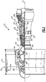
- FIG. 1 schematically illustrates a gas turbine engine 20.
- the gas turbine engine 20 is disclosed herein as a two-spool turbofan that generally incorporates a fan section 22, a compressor section 24, a combustor section 26 and a turbine section 28.
- the fan section 22 drives air along a bypass flow path B in a bypass duct defined within a housing 15 such as a fan case or nacelle, and also drives air along a core flow path C for compression and communication into the combustor section 26 then expansion through the turbine section 28.
- the exemplary engine 20 generally includes a low speed spool 30 and a high speed spool 32 mounted for rotation about an engine central longitudinal axis A relative to an engine static structure 36 via several bearing systems 38. It should be understood that various bearing systems 38 at various locations may alternatively or additionally be provided, and the location of bearing systems 38 may be varied as appropriate to the application.
- the low speed spool 30 generally includes an inner shaft 40 that interconnects, a first (or low) pressure compressor 44 and a first (or low) pressure turbine 46.
- the inner shaft 40 is connected to the fan 42 through a speed change mechanism, which in exemplary gas turbine engine 20 is illustrated as a geared architecture 48 to drive a fan 42 at a lower speed than the low speed spool 30.
- the high speed spool 32 includes an outer shaft 50 that interconnects a second (or high) pressure compressor 52 and a second (or high) pressure turbine 54.
- a combustor 56 is arranged in the exemplary gas turbine 20 between the high pressure compressor 52 and the high pressure turbine 54.
- a mid-turbine frame 57 of the engine static structure 36 may be arranged generally between the high pressure turbine 54 and the low pressure turbine 46.
- the mid-turbine frame 57 further supports bearing systems 38 in the turbine section 28.
- the inner shaft 40 and the outer shaft 50 are concentric and rotate via bearing systems 38 about the engine central longitudinal axis A which is collinear with their longitudinal axes.
- the core airflow is compressed by the low pressure compressor 44 then the high pressure compressor 52, mixed and burned with fuel in the combustor 56, then expanded through the high pressure turbine 54 and low pressure turbine 46.
- the mid-turbine frame 57 includes airfoils 59 which are in the core airflow path C.
- the turbines 46, 54 rotationally drive the respective low speed spool 30 and high speed spool 32 in response to the expansion.
- gear system 48 may be located aft of the low pressure compressor, or aft of the combustor section 26 or even aft of turbine section 28, and fan 42 may be positioned forward or aft of the location of gear system 48.
- the engine 20 in one example is a high-bypass geared aircraft engine.
- the engine 20 bypass ratio is greater than about six (6), with an example embodiment being greater than about ten (10), and can be less than or equal to about 18.0, or more narrowly can be less than or equal to 16.0.
- the geared architecture 48 is an epicyclic gear train, such as a planetary gear system or other gear system, with a gear reduction ratio of greater than about 2.3.
- the gear reduction ratio may be less than or equal to 4.0.
- the low pressure turbine 46 has a pressure ratio that is greater than about five.
- the low pressure turbine pressure ratio can be less than or equal to 13.0, or more narrowly less than or equal to 12.0.
- the engine 20 bypass ratio is greater than about ten (10:1)
- the fan diameter is significantly larger than that of the low pressure compressor 44
- the low pressure turbine 46 has a pressure ratio that is greater than about five 5:1.
- Low pressure turbine 46 pressure ratio is pressure measured prior to an inlet of low pressure turbine 46 as related to the pressure at the outlet of the low pressure turbine 46 prior to an exhaust nozzle.
- the geared architecture 48 may be an epicycle gear train, such as a planetary gear system or other gear system, with a gear reduction ratio of greater than about 2.3:1 and less than about 5:1. It should be understood, however, that the above parameters are only exemplary of one embodiment of a geared architecture engine and that the present invention is applicable to other gas turbine engines including direct drive turbofans.
- the fan section 22 of the engine 20 is designed for a particular flight condition -- typically cruise at about 0.8 Mach and about 35,000 feet (10,668 meters).
- the flight condition of 0.8 Mach and 35,000 ft (10,668 meters), with the engine at its best fuel consumption - also known as "bucket cruise Thrust Specific Fuel Consumption ('TSFC')" - is the industry standard parameter of lbm of fuel being burned divided by lbf of thrust the engine produces at that minimum point.
- 'TSFC' Thrust Specific Fuel Consumption
- “Low fan pressure ratio” is the pressure ratio across the fan blade alone, without a Fan Exit Guide Vane (“FEGV”) system.
- the low fan pressure ratio as disclosed herein according to one non-limiting embodiment is less than about 1.45, or more narrowly greater than or equal to 1.25.
- Low corrected fan tip speed is the actual fan tip speed in ft/sec divided by an industry standard temperature correction of [(Tram °R) / (518.7 °R)] 0.5 .
- the "Low corrected fan tip speed" as disclosed herein according to one non-limiting embodiment is less than about 1150.0 ft / second (350.5 meters/second), and can be greater than or equal to 1000.0 ft / second (304.8 meters/second).
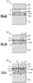
- Figure 2A illustrates a sectioned view of a representative portion of a seal system 60 of the engine 20.
- the seal system 60 may be implemented in the turbine section 28 in association with a turbine vane, a turbine blade, or a blade outer air seal, or in other components in the engine 20 that are exposed to high temperatures, such as the combustor section 26.
- the seal system 60 includes a ceramic component 62 and a metallic component 64, which is formed of a superalloy such as a nickel- or cobalt-based superalloy.
- Figure 2A is representative and the actual geometry of the components will vary depending on the particular implementation.
- the metallic component 64 is a feather seal, which is a thin, generally uniform thickness strip of metal. It is to be understood, however, that the metallic component 64 can alternatively be a component other than a feather seal, such as an adjacent component that serves other functions in addition to sealing.
- the ceramic component 62 is formed of a monolithic ceramic, a ceramic matrix composite (CMC), or a combination of monolithic ceramic and CMC.
- the monolithic ceramic may be, but is not limited to, silicon nitride or silicon carbide.
- a CMC has ceramic fiber tows that are disposed in a ceramic matrix.
- the CMC may be, but is not limited to, a SiC/SiC CMC in which SiC fiber tows are disposed within a SiC matrix.
- a fiber tow is a bundle of filaments. As an example, a single tow may have several thousand filaments.
- the tows may be arranged in a fiber architecture, which refers to an ordered arrangement of the tows relative to one another, such as, but not limited to, a 2D woven ply or a 3D structure.
- the ceramic component 62 includes a first surface region 70, which is a surface area of the ceramic component 62 at which the ceramic component 62 seals with the metallic component 64. Most typically, this will be on the backside of the ceramic component 62 rather than facing into in the core gaspath of the engine 20.
- the gaspath surfaces of a turbine component are often heavily contoured for performance and/or to reduce un-steady pressures which can have a negative impact on the life of adjacent components. This contouring, when mirrored on the non-gaspath surfaces of a ceramic component, such as by the ply layup of a CMC, can significantly impact the ability to achieve an effective seal even with a ductile metallic seal. Just as critical for sealing is the surface finish of the ceramic component.
- the first surface region 70 defines a first surface roughness SRI.
- surface roughness refers to surface roughness Ra (typically in micrometers).
- Surface roughness Ra can be measured using known profilometer or structured light scan equipment and methods.
- a CMC although the fiber tows are embedded in the matrix, the matrix may not completely smooth over the fiber tows. As a result, in comparison to surfaces of metallic components, the surface is relatively rough and "wavy" from protrusion of the tows.
- a monolithic ceramic may not be as rough or wavy as a CMC but still has a relatively rough surface in comparison to metallic components.
- This roughness presents a challenge to sealing because a mating seal, e.g., the metallic component 64, does not conform to the surface roughness, thereby leaving small gaps that may provide pathways for leakage. Moreover, it is undesirable to machine the first surface region 70 of the ceramic component 62 to be smooth, as machining would expose and damage the fiber tows and plies.
- the roughness is also a challenge to meeting geometric flow path requirements. For instance, the position of a gaspath side of a CMC component may be determined by the location of the non-gaspath surface against a mating component. Therefore, if the ceramic component 62 were to have a relatively high roughness at the non-gaspath side, then there would be a greater potential for variation in the position of the gaspath side.
- a silicon-containing layer 66 is provided on the first surface region 70 and serves to fill-in the roughness and smooth the surface of the ceramic component 62 in order to facilitate sealing.
- the silicon-containing layer 66 is deposited by known deposition techniques, such as but not limited to thermal spray, and then machined to a second surface roughness SR2 that is less than the first surface roughness SRI.
- the first surface roughness SRI is greater than 800 Ra and the second surface roughness SR2 is less than 200 Ra.
- the silicon-containing layer 66 is relatively soft and can be readily machined, such as by milling, grinding, or ultrasonic impact machining.
- the top, machined surface of the silicon-containing layer 66 then serves as a contact surface 72 for sealing with the metallic component 64.
- the silicon-containing layer 66 has a thickness of up to about 1500 micrometers, such as 10 micrometers or 250 micrometers. The thickness may be selected in accordance with the desired adherence with the ceramic component 62 and to provide a sufficient amount of material that can be removed in order to meet dimensional requirements of the flow path geometry.
- Figure 2A illustrates the system 60 prior to sealing between the metallic component 64 and the ceramic component 62
- Figure 2B illustrates the system 60 in a sealed state.
- the silicon-containing layer 66 is pure or substantially pure silicon.
- the contact surface 72 provides a smooth surface for sealing
- the metal of the metallic component 64 were to be in direct contact with silicon of the silicon-containing layer 66
- the silicon may migrate and intermix with elements of the metallic component 64, such as nickel or cobalt, to form relatively low melting temperature eutectic phases.
- Ni-Si and Co-Si eutectic phases begin at around 965 °C and 1193 °C, respectively.
- the melting temperatures of these eutectic phases are generally lower than the melting temperature of the superalloy of the metallic component 64. Therefore, eutectic formation may reduce thermal stability and durability.
- a barrier layer 68 is provided on the metallic component 64 to limit or stop interaction between the silicon of the silicon containing layer 66 and the elements of the metallic component 64.
- the metallic component 64 is situated adjacent the ceramic component 62 and includes a second surface region 74 that faces toward the ceramic component 62.
- the barrier layer 68 is a monolayer that is disposed on the second surface region 74. In the sealed state, the barrier layer 68 contacts the contact surface 72 of the silicon-containing layer 66 to provide an airtight or substantially airtight seal.
- the second surface region 74 is relatively smooth and has a roughness of less than 200 Ra.
- the barrier layer 68 can be provided as a thermally grown layer or as a deposited coating. For instance, if the selected superalloy is readily oxidizable at applicable engine temperatures, the barrier layer 68 can be thermally grown via thermal pre-treatment. As an example, some cobalt-based superalloys that contain relatively high levels of chromium are oxidizable, such as but not limited to, the superalloys known as MAR-M-509, Haynes 188, or Haynes 25. Chromium, and possibly some alloying elements of the superalloy, react with oxygen at high temperatures to develop an oxide scale, such as chromia, as the barrier layer 68.
- the oxide scale can be grown as part of the fabrication process of the metallic component 64 by heat treating the metallic component in an oxygen-containing chamber prior to use in the engine, or alternatively grown in-situ in the engine 20 from elevated temperatures and oxygen exposure during engine operation. Mechanical forces, erosion, or other factors may cause loss of portions of the barrier layer 68. However, if the selected superalloy is readily oxidizable, barrier layer 68 will re-grow.
- the barrier layer 68 can instead be deposited onto the metallic component 64 prior to its use in the engine 20.
- an MCrAlY or aluminide coating (including platinum modified aluminides) coating is deposited, and machined or otherwise made flat and smooth, and then thermally treated to produce an alumina scale as the barrier layer 68.
- M is at least one of cobalt (Co), nickel (Ni), or iron (Fe)
- Cr is chromium
- Al aluminum
- Y yttrium.
- the metallic component 64 is a nickel-based superalloy that includes single crystal nickel and the MCrAlY is deposited by, but is not limited to, physical vapor deposition, magnetron sputtering, air plasma spray, vacuum plasma spray, cathodic arc deposition, pack cementation, or chemical vapor deposition.
- an additional oxide layer such as yttria-stabilized zirconia (“YSZ”), can be deposited to form a dual-layer barrier.
- the silicon-containing layer 66 has a first thickness (ti) and the barrier layer 68 has a second thickness (t 2 ).
- the barrier layer 68 is present to mainly block interaction between the silicon and the metal, the barrier layer 68 need only be thick enough to block the silicon over the time frame and temperature of use.
- the barrier layer 68 can be thin in comparison to the silicon-containing layer 66.
- the thickness t2 of the barrier layer 68 is at least 0.5 micrometers
- the thickness t1 of the silicon-containing layer 66 is from 250 to 1500 micrometers.
- FIG. 3 illustrates another example seal system 160 in its sealed state.
- like reference numerals designate like elements where appropriate and reference numerals with the addition of one-hundred or multiples thereof designate modified elements that are understood to incorporate the same features and benefits of the corresponding elements.
- the barrier layer 168 in this example includes the barrier layer 68 as a first sub-layer, along with a second sub-layer 176 on the barrier layer 68.
- the second sub-layer 176 is an oxide that is resistant to and acts as a barrier to silicon from layer 66 while is thermally, chemically, and mechanically compatible with Co-based and Ni-based superalloys.
- One example oxide includes yttria-stabilized zirconia ("YSZ").
- the YSZ of the second sub-layer 176 also provides the metallic component 64 with enhanced wear resistance, thermal resistance, and chemical resistance. YSZ is also thermally, chemically, and mechanically compatible with Co-based and Ni-based superalloys.
- the second sub-layer 176 may be applied by, but is not limited to, air plasma spray and physical vapor deposition.
- the second sub-layer 176 can be polished smooth to an equal or substantially equal roughness as the first surface roughness of the silicon-containing layer 66.
- the second sub-layer 176 has a third thickness (t 3 ).
- the first thickness tl of the silicon-containing layer 66 is greater than each of the second thickness of the barrier layer 68 and the third thickness t3 of the second-sub-layer 176.
- the third thickness t3 is from about 50 micrometers to about 510 micrometers, for example from 75 micrometers to 385 micrometers or from 125 micrometers to 254 micrometers.
- CMC Silicon-based ceramic matrix composites
- monolithic ceramics are desirable for high temperature components in the engine 20 due to their temperature capability and low density.
- Components such as CMC or monolithic ceramic vanes, blades, and blade outer air seals are segmented circumferentially, and typically multiple parts make up a given row. The intersegment or mate-face gaps between these parts must be sealed in order to reduce exposure of metallic hardware to hot gas-path air ingestion.
- the seal systems here may be implemented pursuant to such purposes and to control leakage of secondary airflow, which may otherwise debit engine performance.
Landscapes
- Engineering & Computer Science (AREA)
- General Engineering & Computer Science (AREA)
- Mechanical Engineering (AREA)
- Chemical & Material Sciences (AREA)
- Combustion & Propulsion (AREA)
- Ceramic Engineering (AREA)
- Materials Engineering (AREA)
- Structural Engineering (AREA)
- Organic Chemistry (AREA)
- Turbine Rotor Nozzle Sealing (AREA)
- Structures Of Non-Positive Displacement Pumps (AREA)
Applications Claiming Priority (1)
| Application Number | Priority Date | Filing Date | Title |
|---|---|---|---|
| US17/377,591 US11674448B2 (en) | 2021-07-16 | 2021-07-16 | Seal system having silicon layer and barrier layer |
Publications (1)
| Publication Number | Publication Date |
|---|---|
| EP4119773A1 true EP4119773A1 (de) | 2023-01-18 |
Family
ID=82608498
Family Applications (1)
| Application Number | Title | Priority Date | Filing Date |
|---|---|---|---|
| EP22185191.8A Pending EP4119773A1 (de) | 2021-07-16 | 2022-07-15 | Dichtungssystem mit siliziumschicht und sperrschicht |
Country Status (2)
| Country | Link |
|---|---|
| US (1) | US11674448B2 (de) |
| EP (1) | EP4119773A1 (de) |
Families Citing this family (2)
| Publication number | Priority date | Publication date | Assignee | Title |
|---|---|---|---|---|
| US20240246872A1 (en) * | 2023-01-20 | 2024-07-25 | Raytheon Technologies Corporation | Sealing interface |
| US12281575B2 (en) * | 2023-01-20 | 2025-04-22 | Rtx Corporation | Ceramic component having silicon layer and barrier layer |
Citations (6)
| Publication number | Priority date | Publication date | Assignee | Title |
|---|---|---|---|---|
| US5498484A (en) * | 1990-05-07 | 1996-03-12 | General Electric Company | Thermal barrier coating system with hardenable bond coat |
| WO2002062519A1 (en) * | 2001-02-05 | 2002-08-15 | Rutgers, The State University | Transient eutectic phase process for ceramic-metal bonding, metallilzation, and compositing |
| EP1693478A2 (de) * | 2005-02-18 | 2006-08-23 | The General Electric Company | Diffusionssperschicht zur Montage mit metallischen und Silizium-enthaltenden Bauteilen und Verfahren zur Herstellung |
| EP2963250A1 (de) * | 2014-06-30 | 2016-01-06 | Rolls-Royce Corporation | Beschichtung zur isolierung von metallischen bauteilen von verbundbauteilen |
| EP3626934A1 (de) * | 2018-09-24 | 2020-03-25 | United Technologies Corporation | Turbinenabschnitt mit einer federdichtung aus cmc-material |
| FR3101642A1 (fr) * | 2019-10-03 | 2021-04-09 | Safran Ceramics | Etanchéité d’une turbine |
Family Cites Families (33)
| Publication number | Priority date | Publication date | Assignee | Title |
|---|---|---|---|---|
| US3928906A (en) * | 1972-03-06 | 1975-12-30 | Kelsey Hayes Co | Method of making a turbine regenerative seal |
| US4109031A (en) * | 1976-12-27 | 1978-08-22 | United Technologies Corporation | Stress relief of metal-ceramic gas turbine seals |
| US4481237A (en) * | 1981-12-14 | 1984-11-06 | United Technologies Corporation | Method of applying ceramic coatings on a metallic substrate |
| JPS60131875A (ja) * | 1983-12-20 | 1985-07-13 | 三菱重工業株式会社 | セラミツクと金属の接合法 |
| US6413589B1 (en) * | 1988-11-29 | 2002-07-02 | Chou H. Li | Ceramic coating method |
| JP2528718B2 (ja) * | 1989-11-30 | 1996-08-28 | いすゞ自動車株式会社 | セラミックスと金属の接合方法 |
| US5279909A (en) * | 1992-05-01 | 1994-01-18 | General Atomics | Compact multilayer ceramic-to-metal seal structure |
| US5490627A (en) * | 1994-06-30 | 1996-02-13 | Hughes Aircraft Company | Direct bonding of copper composites to ceramics |
| US7989086B2 (en) * | 2003-11-05 | 2011-08-02 | Hamilton Sundstrand Corporation | High temperature seal for joining ceramic components such as cells in a ceramic oxygen generator |
| US9365725B2 (en) * | 2007-11-16 | 2016-06-14 | General Electric Company | Articles for high temperature service and methods for their manufacture |
| CA2695850A1 (en) * | 2009-03-06 | 2010-09-06 | Pratt & Whitney Canada Corp. | Thermal barrier coating with lower thermal conductivity |
| US20110027517A1 (en) * | 2009-07-31 | 2011-02-03 | Glen Harold Kirby | Methods of improving surface roughness of an environmental barrier coating and components comprising environmental barrier coatings having improved surface roughness |
| US20110027557A1 (en) * | 2009-07-31 | 2011-02-03 | Glen Harold Kirby | Solvent based environmental barrier coatings for high temperature ceramic components |
| US20140261080A1 (en) * | 2010-08-27 | 2014-09-18 | Rolls-Royce Corporation | Rare earth silicate environmental barrier coatings |
| US8770926B2 (en) * | 2010-10-25 | 2014-07-08 | United Technologies Corporation | Rough dense ceramic sealing surface in turbomachines |
| US8770927B2 (en) * | 2010-10-25 | 2014-07-08 | United Technologies Corporation | Abrasive cutter formed by thermal spray and post treatment |
| WO2014137804A1 (en) * | 2013-03-05 | 2014-09-12 | Rolls-Royce Corporation | Long life low cost environmental barrier coating for ceramic matrix composites |
| WO2015050704A1 (en) * | 2013-10-02 | 2015-04-09 | United Technologies Corporation | Turbine abradable air seal system |
| US9890089B2 (en) * | 2014-03-11 | 2018-02-13 | General Electric Company | Compositions and methods for thermal spraying a hermetic rare earth environmental barrier coating |
| US10399911B2 (en) * | 2015-01-27 | 2019-09-03 | Rolls-Royce Corporation | Forming a surface layer of a ceramic matrix composite article |
| US10273192B2 (en) * | 2015-02-17 | 2019-04-30 | Rolls-Royce Corporation | Patterned abradable coating and methods for the manufacture thereof |
| US20180010469A1 (en) * | 2015-02-18 | 2018-01-11 | Siemens Aktiengesellschaft | Turbine component thermal barrier coating with crack isolating, cascading, multifurcated engineered groove features |
| US20180066527A1 (en) * | 2015-02-18 | 2018-03-08 | Siemens Aktiengesellschaft | Turbine component thermal barrier coating with vertically aligned, engineered surface and multifurcated groove features |
| US10100656B2 (en) | 2015-08-25 | 2018-10-16 | General Electric Company | Coated seal slot systems for turbomachinery and methods for forming the same |
| US10669878B2 (en) * | 2016-03-23 | 2020-06-02 | Raytheon Technologies Corporation | Outer airseal abradable rub strip |
| US10697464B2 (en) * | 2016-07-29 | 2020-06-30 | Raytheon Technologies Corporation | Abradable material |
| DE102017218844A1 (de) * | 2016-11-07 | 2018-05-09 | Aktiebolaget Skf | Beschichtungsverfahren für einen Lagerring |
| US20180320270A1 (en) * | 2017-05-08 | 2018-11-08 | United Technologies Corporation | Functionally graded environmental barrier coating |
| JP6744259B2 (ja) * | 2017-07-03 | 2020-08-19 | タツタ電線株式会社 | 金属セラミックス基材、金属セラミックス接合構造、金属セラミックス接合構造の作製方法、及び混合粉末材料 |
| US10900371B2 (en) * | 2017-07-27 | 2021-01-26 | Rolls-Royce North American Technologies, Inc. | Abradable coatings for high-performance systems |
| US10947625B2 (en) * | 2017-09-08 | 2021-03-16 | Raytheon Technologies Corporation | CMAS-resistant thermal barrier coating and method of making a coating thereof |
| US10871078B2 (en) * | 2017-09-27 | 2020-12-22 | Rolls-Royce Corporation | Low porosity abradable coating |
| US10808553B2 (en) | 2018-11-13 | 2020-10-20 | Rolls-Royce Plc | Inter-component seals for ceramic matrix composite turbine vane assemblies |
-
2021
- 2021-07-16 US US17/377,591 patent/US11674448B2/en active Active
-
2022
- 2022-07-15 EP EP22185191.8A patent/EP4119773A1/de active Pending
Patent Citations (6)
| Publication number | Priority date | Publication date | Assignee | Title |
|---|---|---|---|---|
| US5498484A (en) * | 1990-05-07 | 1996-03-12 | General Electric Company | Thermal barrier coating system with hardenable bond coat |
| WO2002062519A1 (en) * | 2001-02-05 | 2002-08-15 | Rutgers, The State University | Transient eutectic phase process for ceramic-metal bonding, metallilzation, and compositing |
| EP1693478A2 (de) * | 2005-02-18 | 2006-08-23 | The General Electric Company | Diffusionssperschicht zur Montage mit metallischen und Silizium-enthaltenden Bauteilen und Verfahren zur Herstellung |
| EP2963250A1 (de) * | 2014-06-30 | 2016-01-06 | Rolls-Royce Corporation | Beschichtung zur isolierung von metallischen bauteilen von verbundbauteilen |
| EP3626934A1 (de) * | 2018-09-24 | 2020-03-25 | United Technologies Corporation | Turbinenabschnitt mit einer federdichtung aus cmc-material |
| FR3101642A1 (fr) * | 2019-10-03 | 2021-04-09 | Safran Ceramics | Etanchéité d’une turbine |
Also Published As
| Publication number | Publication date |
|---|---|
| US20230019497A1 (en) | 2023-01-19 |
| US11674448B2 (en) | 2023-06-13 |
Similar Documents
| Publication | Publication Date | Title |
|---|---|---|
| US10794211B2 (en) | Seal geometries for reduced leakage in gas turbines and methods of forming | |
| US11781486B2 (en) | Ceramic component having silicon layer and barrier layer | |
| EP2540868B1 (de) | Splitterbeständige abreibbare turbinenluftdichtung | |
| US20120189434A1 (en) | Coating with abradability proportional to interaction rate | |
| US8770927B2 (en) | Abrasive cutter formed by thermal spray and post treatment | |
| US12281575B2 (en) | Ceramic component having silicon layer and barrier layer | |
| US11131206B2 (en) | Substrate edge configurations for ceramic coatings | |
| EP4119773A1 (de) | Dichtungssystem mit siliziumschicht und sperrschicht | |
| US12123307B2 (en) | Air seal system with backside abradable layer | |
| EP3196419A1 (de) | Äussere laufschaufelluftdichtung mit einer oberflächenschicht mit taschen | |
| EP3421729B1 (de) | Aluminiumoxidabdichtungsbeschichtung mit zwischenschicht | |
| US20260110096A1 (en) | Turbine blade outermost abrasive layer using graded ceramics | |
| US20150300180A1 (en) | Gas turbine engine turbine blade tip with coated recess | |
| US12110797B1 (en) | Blade outer air seal with seal plate and flexible seal | |
| KR20260058161A (ko) | 경사 세라믹을 사용하는 터빈 블레이드 최외측 연마층 | |
| EP4071337B1 (de) | Keramische komponente mit tragstruktur | |
| US20250250900A1 (en) | Aerofoil structure for a gas turbine engine | |
| EP3556998B1 (de) | Luftdichtung mit gaswegabschnitt mit geometrisch segmentierter beschichtung |
Legal Events
| Date | Code | Title | Description |
|---|---|---|---|
| PUAI | Public reference made under article 153(3) epc to a published international application that has entered the european phase |
Free format text: ORIGINAL CODE: 0009012 |
|
| STAA | Information on the status of an ep patent application or granted ep patent |
Free format text: STATUS: THE APPLICATION HAS BEEN PUBLISHED |
|
| AK | Designated contracting states |
Kind code of ref document: A1 Designated state(s): AL AT BE BG CH CY CZ DE DK EE ES FI FR GB GR HR HU IE IS IT LI LT LU LV MC MK MT NL NO PL PT RO RS SE SI SK SM TR |
|
| STAA | Information on the status of an ep patent application or granted ep patent |
Free format text: STATUS: REQUEST FOR EXAMINATION WAS MADE |
|
| 17P | Request for examination filed |
Effective date: 20230718 |
|
| RBV | Designated contracting states (corrected) |
Designated state(s): AL AT BE BG CH CY CZ DE DK EE ES FI FR GB GR HR HU IE IS IT LI LT LU LV MC MK MT NL NO PL PT RO RS SE SI SK SM TR |
|
| RAP3 | Party data changed (applicant data changed or rights of an application transferred) |
Owner name: RTX CORPORATION |
|
| STAA | Information on the status of an ep patent application or granted ep patent |
Free format text: STATUS: EXAMINATION IS IN PROGRESS |
|
| 17Q | First examination report despatched |
Effective date: 20250626 |