EP4119785A1 - Dispositif d'injection de carburant pour un moteur à combustion interne, en particulier pour un moteur à combustion d'hydrogène - Google Patents
Dispositif d'injection de carburant pour un moteur à combustion interne, en particulier pour un moteur à combustion d'hydrogène Download PDFInfo
- Publication number
- EP4119785A1 EP4119785A1 EP22182101.0A EP22182101A EP4119785A1 EP 4119785 A1 EP4119785 A1 EP 4119785A1 EP 22182101 A EP22182101 A EP 22182101A EP 4119785 A1 EP4119785 A1 EP 4119785A1
- Authority
- EP
- European Patent Office
- Prior art keywords
- fuel
- injection device
- fuel injection
- central rail
- pressure accumulator
- Prior art date
- Legal status (The legal status is an assumption and is not a legal conclusion. Google has not performed a legal analysis and makes no representation as to the accuracy of the status listed.)
- Granted
Links
Images


Classifications
-
- F—MECHANICAL ENGINEERING; LIGHTING; HEATING; WEAPONS; BLASTING
- F02—COMBUSTION ENGINES; HOT-GAS OR COMBUSTION-PRODUCT ENGINE PLANTS
- F02M—SUPPLYING COMBUSTION ENGINES IN GENERAL WITH COMBUSTIBLE MIXTURES OR CONSTITUENTS THEREOF
- F02M63/00—Other fuel-injection apparatus having pertinent characteristics not provided for in groups F02M39/00 - F02M57/00 or F02M67/00; Details, component parts, or accessories of fuel-injection apparatus, not provided for in, or of interest apart from, the apparatus of groups F02M39/00 - F02M61/00 or F02M67/00; Combination of fuel pump with other devices, e.g. lubricating oil pump
- F02M63/02—Fuel-injection apparatus having several injectors fed by a common pumping element, or having several pumping elements feeding a common injector; Fuel-injection apparatus having provisions for cutting-out pumps, pumping elements, or injectors; Fuel-injection apparatus having provisions for variably interconnecting pumping elements and injectors alternatively
- F02M63/0225—Fuel-injection apparatus having a common rail feeding several injectors ; Means for varying pressure in common rails; Pumps feeding common rails
-
- F—MECHANICAL ENGINEERING; LIGHTING; HEATING; WEAPONS; BLASTING
- F02—COMBUSTION ENGINES; HOT-GAS OR COMBUSTION-PRODUCT ENGINE PLANTS
- F02M—SUPPLYING COMBUSTION ENGINES IN GENERAL WITH COMBUSTIBLE MIXTURES OR CONSTITUENTS THEREOF
- F02M21/00—Apparatus for supplying engines with non-liquid fuels, e.g. gaseous fuels stored in liquid form
- F02M21/02—Apparatus for supplying engines with non-liquid fuels, e.g. gaseous fuels stored in liquid form for gaseous fuels
- F02M21/0218—Details on the gaseous fuel supply system, e.g. tanks, valves, pipes, pumps, rails, injectors or mixers
- F02M21/023—Valves; Pressure or flow regulators in the fuel supply or return system
- F02M21/0239—Pressure or flow regulators therefor
-
- F—MECHANICAL ENGINEERING; LIGHTING; HEATING; WEAPONS; BLASTING
- F02—COMBUSTION ENGINES; HOT-GAS OR COMBUSTION-PRODUCT ENGINE PLANTS
- F02B—INTERNAL-COMBUSTION PISTON ENGINES; COMBUSTION ENGINES IN GENERAL
- F02B43/00—Engines characterised by operating on gaseous fuels; Plants including such engines
-
- F—MECHANICAL ENGINEERING; LIGHTING; HEATING; WEAPONS; BLASTING
- F02—COMBUSTION ENGINES; HOT-GAS OR COMBUSTION-PRODUCT ENGINE PLANTS
- F02D—CONTROLLING COMBUSTION ENGINES
- F02D19/00—Controlling engines characterised by their use of non-liquid fuels, pluralities of fuels, or non-fuel substances added to the combustible mixtures
- F02D19/02—Controlling engines characterised by their use of non-liquid fuels, pluralities of fuels, or non-fuel substances added to the combustible mixtures peculiar to engines working with gaseous fuels
- F02D19/021—Control of components of the fuel supply system
- F02D19/022—Control of components of the fuel supply system to adjust the fuel pressure, temperature or composition
-
- F—MECHANICAL ENGINEERING; LIGHTING; HEATING; WEAPONS; BLASTING
- F02—COMBUSTION ENGINES; HOT-GAS OR COMBUSTION-PRODUCT ENGINE PLANTS
- F02D—CONTROLLING COMBUSTION ENGINES
- F02D19/00—Controlling engines characterised by their use of non-liquid fuels, pluralities of fuels, or non-fuel substances added to the combustible mixtures
- F02D19/02—Controlling engines characterised by their use of non-liquid fuels, pluralities of fuels, or non-fuel substances added to the combustible mixtures peculiar to engines working with gaseous fuels
- F02D19/026—Measuring or estimating parameters related to the fuel supply system
- F02D19/027—Determining the fuel pressure, temperature or volume flow, the fuel tank fill level or a valve position
-
- F—MECHANICAL ENGINEERING; LIGHTING; HEATING; WEAPONS; BLASTING
- F02—COMBUSTION ENGINES; HOT-GAS OR COMBUSTION-PRODUCT ENGINE PLANTS
- F02M—SUPPLYING COMBUSTION ENGINES IN GENERAL WITH COMBUSTIBLE MIXTURES OR CONSTITUENTS THEREOF
- F02M21/00—Apparatus for supplying engines with non-liquid fuels, e.g. gaseous fuels stored in liquid form
- F02M21/02—Apparatus for supplying engines with non-liquid fuels, e.g. gaseous fuels stored in liquid form for gaseous fuels
- F02M21/0203—Apparatus for supplying engines with non-liquid fuels, e.g. gaseous fuels stored in liquid form for gaseous fuels characterised by the type of gaseous fuel
- F02M21/0206—Non-hydrocarbon fuels, e.g. hydrogen, ammonia or carbon monoxide
-
- F—MECHANICAL ENGINEERING; LIGHTING; HEATING; WEAPONS; BLASTING
- F02—COMBUSTION ENGINES; HOT-GAS OR COMBUSTION-PRODUCT ENGINE PLANTS
- F02M—SUPPLYING COMBUSTION ENGINES IN GENERAL WITH COMBUSTIBLE MIXTURES OR CONSTITUENTS THEREOF
- F02M21/00—Apparatus for supplying engines with non-liquid fuels, e.g. gaseous fuels stored in liquid form
- F02M21/02—Apparatus for supplying engines with non-liquid fuels, e.g. gaseous fuels stored in liquid form for gaseous fuels
- F02M21/0218—Details on the gaseous fuel supply system, e.g. tanks, valves, pipes, pumps, rails, injectors or mixers
- F02M21/0221—Fuel storage reservoirs, e.g. cryogenic tanks
- F02M21/0224—Secondary gaseous fuel storages
-
- F—MECHANICAL ENGINEERING; LIGHTING; HEATING; WEAPONS; BLASTING
- F02—COMBUSTION ENGINES; HOT-GAS OR COMBUSTION-PRODUCT ENGINE PLANTS
- F02M—SUPPLYING COMBUSTION ENGINES IN GENERAL WITH COMBUSTIBLE MIXTURES OR CONSTITUENTS THEREOF
- F02M21/00—Apparatus for supplying engines with non-liquid fuels, e.g. gaseous fuels stored in liquid form
- F02M21/02—Apparatus for supplying engines with non-liquid fuels, e.g. gaseous fuels stored in liquid form for gaseous fuels
- F02M21/0218—Details on the gaseous fuel supply system, e.g. tanks, valves, pipes, pumps, rails, injectors or mixers
- F02M21/023—Valves; Pressure or flow regulators in the fuel supply or return system
-
- F—MECHANICAL ENGINEERING; LIGHTING; HEATING; WEAPONS; BLASTING
- F02—COMBUSTION ENGINES; HOT-GAS OR COMBUSTION-PRODUCT ENGINE PLANTS
- F02M—SUPPLYING COMBUSTION ENGINES IN GENERAL WITH COMBUSTIBLE MIXTURES OR CONSTITUENTS THEREOF
- F02M21/00—Apparatus for supplying engines with non-liquid fuels, e.g. gaseous fuels stored in liquid form
- F02M21/02—Apparatus for supplying engines with non-liquid fuels, e.g. gaseous fuels stored in liquid form for gaseous fuels
- F02M21/0218—Details on the gaseous fuel supply system, e.g. tanks, valves, pipes, pumps, rails, injectors or mixers
- F02M21/023—Valves; Pressure or flow regulators in the fuel supply or return system
- F02M21/0233—Details of actuators therefor
-
- F—MECHANICAL ENGINEERING; LIGHTING; HEATING; WEAPONS; BLASTING
- F02—COMBUSTION ENGINES; HOT-GAS OR COMBUSTION-PRODUCT ENGINE PLANTS
- F02M—SUPPLYING COMBUSTION ENGINES IN GENERAL WITH COMBUSTIBLE MIXTURES OR CONSTITUENTS THEREOF
- F02M21/00—Apparatus for supplying engines with non-liquid fuels, e.g. gaseous fuels stored in liquid form
- F02M21/02—Apparatus for supplying engines with non-liquid fuels, e.g. gaseous fuels stored in liquid form for gaseous fuels
- F02M21/0218—Details on the gaseous fuel supply system, e.g. tanks, valves, pipes, pumps, rails, injectors or mixers
- F02M21/0245—High pressure fuel supply systems; Rails; Pumps; Arrangement of valves
-
- F—MECHANICAL ENGINEERING; LIGHTING; HEATING; WEAPONS; BLASTING
- F02—COMBUSTION ENGINES; HOT-GAS OR COMBUSTION-PRODUCT ENGINE PLANTS
- F02D—CONTROLLING COMBUSTION ENGINES
- F02D2200/00—Input parameters for engine control
- F02D2200/02—Input parameters for engine control the parameters being related to the engine
- F02D2200/06—Fuel or fuel supply system parameters
- F02D2200/0602—Fuel pressure
-
- F—MECHANICAL ENGINEERING; LIGHTING; HEATING; WEAPONS; BLASTING
- F02—COMBUSTION ENGINES; HOT-GAS OR COMBUSTION-PRODUCT ENGINE PLANTS
- F02M—SUPPLYING COMBUSTION ENGINES IN GENERAL WITH COMBUSTIBLE MIXTURES OR CONSTITUENTS THEREOF
- F02M2200/00—Details of fuel-injection apparatus, not otherwise provided for
- F02M2200/40—Fuel-injection apparatus with fuel accumulators, e.g. a fuel injector having an integrated fuel accumulator
-
- Y—GENERAL TAGGING OF NEW TECHNOLOGICAL DEVELOPMENTS; GENERAL TAGGING OF CROSS-SECTIONAL TECHNOLOGIES SPANNING OVER SEVERAL SECTIONS OF THE IPC; TECHNICAL SUBJECTS COVERED BY FORMER USPC CROSS-REFERENCE ART COLLECTIONS [XRACs] AND DIGESTS
- Y02—TECHNOLOGIES OR APPLICATIONS FOR MITIGATION OR ADAPTATION AGAINST CLIMATE CHANGE
- Y02T—CLIMATE CHANGE MITIGATION TECHNOLOGIES RELATED TO TRANSPORTATION
- Y02T10/00—Road transport of goods or passengers
- Y02T10/10—Internal combustion engine [ICE] based vehicles
- Y02T10/30—Use of alternative fuels, e.g. biofuels
Definitions
- the invention relates to a fuel injection device for an internal combustion engine, comprising at least one rail that is part of two fuel paths.
- the opening duration of the specific injector, via which the current fuel supply is to take place in the respective combustion chamber, is lengthened.
- the drop in rail pressure caused by this is kept within certain limits even with a longer injection duration and thus an increased fuel delivery quantity from the rail, which enables compensation with regard to the fuel delivery rate.
- this additional opening time of the injector can in turn contain the period of time that includes the drop in the fuel mass flow that occurs as a result of the drop in rail pressure.
- the rail pump delivers a higher fuel quantity, which leads to the rail pressure setpoint being reached again even if the increased fuel consumption persists.
- a rail pump that is in delivery mode usually delivers such a quantity of fuel to the rail that is at least slightly greater than the instantaneous fuel consumption of the internal combustion engine. If the rail pressure has reached or already exceeded its target value, the excess amount of fuel is diverted from the rail and generally fed back into the primary fuel tank.
- liquids can be compressed much more easily than gases to a pressure level of a few 10 bar up to many hundreds of bar, at the same time have a significantly higher volumetric density than gases and the widespread liquid fuels (diesel and diesel-like fuels, petrol, LPG, etc. ) can be stored under atmospheric or slightly higher pressure at normal ambient temperatures in a primary fuel tank that is simple in design and handling, the above-mentioned measures are technically still comparatively easy to implement with regard to the possibility of a rapid increase in the fuel supply rate for the aforementioned fuels. In other words: assuming that high-pressure fuel injection exists or is mandatory, the additional effort required to be able to increase the supply of liquid fuel within a short period of time is comparatively low.
- a rapid increase in the mechanical power output of an internal combustion engine also requires a corresponding dynamic increase in the amount of air to be supplied. If the request for a transient power increase occurs during an initial situation in which the momentary air supply into the combustion chambers is limited by throttling in the air path and/or the admixture of exhaust gas, at least a certain increase in the air supply is relatively short-term possible. Furthermore, certain aids are known with which the air supply can be increased significantly and in a comparatively short-term manner, for example by means of an electrically driven compressor integrated in the air path.
- the rail pressure can be increased quickly and easily.
- a comparatively high proportion of the gaseous fuel in the primary tank cannot be used with a correspondingly high desired value.
- the gaseous fuel has a very low boiling point and is stored as liquid gas, conditioning the fuel requires it to be heated to a high degree.
- an increase in fuel demand i.e. an increase in compressed gaseous fuel in terms of the required pressure level and quantity, entails the need for a temporally and locally coordinated increase in the heat input into the fuel supply path.
- fuels are liquid hydrogen and liquefied natural gas.
- the gaseous fuel in the primary tank is not stored in its molecular form, but chemically bound, an increased supply of fuel in terms of its pressure level and its quantity includes all process steps along a multi-stage conditioning path.
- LOHC Liquid Organic Hydrogen Carriers
- this carrier liquid must first be conditioned for a reformation process and must go through this conditioning process.
- the resulting molecular hydrogen is then already in gas form and must then be compressed (again) if the pressure level required in the rail is higher than the corresponding pressure level under which the liquid organic hydrogen carrier can be fed to the reformation process in order to to obtain compressed hydrogen to a corresponding extent.
- the object of the present invention is to provide a modified fuel injection device which is distinguished by a simple construction in terms of apparatus and offers an energy-efficient option for rapidly increasing the fuel supply rate up to the intended maximum rate in the combustion chambers.
- the injection device it is proposed to supplement the injection device with at least one additional fuel pressure accumulator, the internal volume of which is connected to the at least one rail via at least one control valve.
- the internal combustion engine has several combustion chambers, there is preferably a so-called central rail over which the fuel path extends to supply several or all of the combustion chambers.
- the valve actuation allows the fluid connection between the additional fuel accumulator and the central rail to be opened and closed as required. This opens up the possibility of making a larger quantity of fuel available to the central rail for a limited period of time, ie almost without delay.
- the control valve is open, in addition to the regular fuel path from the primary fuel tank, the central rail is also supplied with a certain amount of fuel from the additional fuel pressure accumulator.
- Such a parallel supply from the primary fuel tank and the additional fuel pressure accumulator makes sense particularly in the case of a comparatively high rate of increase in the desired fuel metering. Due to the additional supply of fuel from the additional fuel pressure reservoir, a pressure drop in the central rail can be avoided or reduced, which would otherwise be present or occur to a significantly greater extent due to the longer opening times of the injectors. If there is a sufficiently high fuel reserve in the additional fuel pressure accumulator, a possible fuel deficit can be compensated for until the regular fuel path from the primary fuel tank to the central rail has been adapted to the higher fuel supply.
- the primary fuel tank is suitable for providing the fuel, in particular hydrogen, it being possible for the fuel to be stored in the primary tank in liquid or gaseous form.
- the hydrogen may be in (i) molecular form, or (i) alternatively, as a gas admixed in molecular form to another fuel gas, e.g.
- methane or (iii) alternatively, be stored in such a chemically bound form that a so-called hydrogen reformation occurs in that System example.
- a preloaded pressure accumulator is preferably used as the additional fuel pressure accumulator.
- the use of a bladder accumulator is conceivable.
- connection between the additional fuel pressure accumulator and the central rail that extends only via the control valve and is otherwise direct.
- the fluid connection should be kept as short as possible so that the reaction time is as short as possible. This is crucial in order to be able to compensate for any fuel deficit, which can be caused by a sharp increase in the target delivery quantity, as quickly as possible or even to prevent it, thereby keeping a pressure drop in the central rail low or ideally avoiding it.
- a particularly short line route between the central rail and the additional fuel accumulator arises in the event that the additional fuel pressure accumulator is arranged directly on the central rail or at least in the immediate vicinity of the central rail.
- the fluid connection between the central rail and the additional fuel pressure accumulator extends only along aligned openings in the housing walls of the central rail and the additional fuel pressure accumulator.
- the control valve and any sealing elements can be partially or completely integrated in a housing of the additional fuel pressure accumulator or the central rail.
- all gas paths leading to and leading from the auxiliary fuel accumulator extend exclusively across the central rail.
- the fuel is fed into the additional fuel pressure accumulator via the central rail.
- the additional fuel pressure accumulator can also be charged in portions if no fuel is drawn from the additional fuel pressure accumulator between two or more subsequent charging processes, as can be shown using a simple example: Within a certain period of time there is an operating phase in which the internal combustion engine is working at around 50% full load, for example, and the instantaneous fuel supply can already be completely covered by simultaneous fuel removal from the primary tank. If the internal pressure in the additional fuel pressure accumulator is lower than the rail pressure, the corresponding control valve is actuated accordingly, so that after a while the pressure in the additional fuel pressure accumulator has the same value as the rail pressure.
- a simple and inexpensive design of the control valve as a simple directional control valve that only has two switching states and therefore does not allow a continuous change in the flow rate is sufficient.
- the valve can be actuated by an actuator based, for example, on an electromagnet.
- the operating environment requires a physical separation and/or isolation of the actuator, in particular the electrical part, from the fluid-carrying, i.e. the fuel-carrying components, in particular the valve part.
- the central rail can be equipped with at least one internal pressure sensor integrated therein in order to monitor the current rail pressure and/or be part of a rail pressure control system. It is expedient to place the rail pressure sensor within the central rail so that it is as protected as possible from a possible pressure wave in order to ensure that representative measured values are recorded.
- the pressure sensor should be positioned at a sufficient distance from the inlet passage of the fluid connection of the additional fuel pressure accumulator on the central rail.
- the auxiliary fuel accumulator can be equipped with its own physically present internal pressure sensor.
- the state of the additional fuel pressure accumulator can also be monitored by evaluating the measured values of the rail pressure sensor.
- the currently measured pressure value of the rail pressure sensor can be selected as a substitute value for the internal pressure in the additional fuel pressure accumulator, whereas when a closed control valve is present, the respective end value of the rail pressure sensor at the time is used as a substitute value for the internal pressure of the additional fuel pressure accumulator is used immediately before the last closing of the control valve.
- a software-supported evaluation of several raw data sampled values is preferably used in order to obtain a rail pressure value considered relevant, which is then used for all further processes, including any subsequent calculations that are to be influenced by the actual rail pressure value.
- such a procedure is appropriate for the raw measured values obtained from a pressure sensor and/or temperature sensor, etc. that may be present and that can be installed inside the additional fuel pressure accumulator.
- the fuel injector may be equipped with a controller configured to keep the control valve closed during normal engine operation.
- the controller can be configured to open the control valve as of a specific increase in the required setpoint fuel metering, in particular when the associated rate of increase is above a certain threshold value in relation to the currently available fuel supply quantity. After opening the control valve, it can be kept open for a certain period of time and/or depending on certain parameters—for example, the fuel quantity to be substituted, the pressure difference in the rail and the additional fuel pressure accumulator, etc. It may be better not to keep the control valve open continuously, but to open and close it alternately as a function of the aforementioned and other criteria, ie the control valve is according to FIG switched to a fixed and preferably variably definable cycle.
- the switching cycle can preferably be determined dynamically, in particular on the basis of one or more engine operating parameters and/or operating variables of the internal combustion engine.
- the current rail pressure and/or the current engine speed or crankshaft speed and/or the target value of the fuel metering that can currently be carried out and/or the desired value for the current fuel metering can be relevant.
- control can include the coordination for charging the additional fuel pressure accumulator via the central rail.
- the controller takes into account the current internal pressures of the additional fuel pressure accumulator and the central rail and the currently possible fuel delivery rate into the central rail. If the internal pressure in the additional fuel pressure accumulator is lower than the internal pressure in the central rail, the control valve can be opened to equalize the pressure between the additional fuel pressure accumulator and the central rail. This is sensibly coordinated as a function of the current load or currently required fuel quantity, taking into account the currently possible fuel delivery rate, so that the current fuel supply to the internal combustion engine is not impaired by a current charging of the additional fuel pressure accumulator.
- the controller causes the control valve to close at the latest when the pressure between the two accumulators has equalized.
- the fuel injection device With the fuel injection device according to the invention, dynamic control of the fuel supply rate that can be provided from a central rail is possible.
- influencing the air path of the internal combustion engine can also be considered. It is conceivable, for example, that the controller that coordinates the opening and closing of the control valve, possibly in an extended coordination with a monitoring of the air path and options for intervention in the air path, the control valve and/or one or more actuators in the air path, such as a throttle valve or a switchable device by means of which an increase in charge air compression can be achieved.
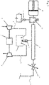
- FIG 1 shows a first exemplary embodiment of the invention with the injection device according to the invention for direct injection into the combustion chamber 1 of an internal combustion engine.
- the present case is a gas engine that is operated with hydrogen as the fuel.
- an injector 2 via which the required quantity of fuel is injected into the combustion chamber 1 of the internal combustion engine.
- the injector 2 or all injectors of the internal combustion engine are supplied from a central rail 10 which is connected to the primary fuel tank (not shown) via a primary fuel path 12 provided with the rail pressure control valve 11 .
- the internal combustion engine is over the charge air path 8 provided the amount of air required for combustion. This is a supercharged internal combustion engine.
- the turbine 3 is driven by the exhaust gas volume flow in the exhaust gas path 6 and drives the compressor 4 to compress the charge air in the charge air path 8 .
- An electric machine 7 can be present as support, in order to be able to supply additional drive power to the compressor 4 if a rapid increase in the available quantity of charge air is required.
- the idea according to the invention provides that the central rail 10 is supplied with fuel exclusively via the primary fuel path 12 during normal operation, but in the event of a certain rate of increase in the requested setpoint fuel quantity for the combustion chamber 1, however, an additional fuel quantity from a separate additional fuel pressure accumulator 20 is deployable.
- the additional fuel pressure accumulator 20, designed here as a preloaded pressure accumulator, is fluidically connected directly to the central rail 10 via a control valve 13 designed as a 2/2-way valve, whereby an additional fuel quantity can be made available over the shortest possible line route within a short reaction time.
- the control valve 13 is actuated via an electromagnet 14 which acts on the control valve 13 via a tappet.
- the additional fuel pressure reservoir 20 has a certain amount of fuel, ie there is a certain pressure level in it, the control valve 13 is opened when there is a sharp increase in the target output power of the internal combustion engine. As a result, a higher fuel supply rate is temporarily available, which can be made available to the combustion chambers 1 immediately in terms of time. If there is a sufficiently high fuel reserve in the additional fuel pressure accumulator 20, the occurrence of a fuel deficit can be compensated for until the device for providing fuel from the primary fuel tank, which is located in the primary fuel path 12, has adapted to the required higher fuel supply rate and the Occurrence of a fuel deficit has become unnecessary.
- the additional fuel pressure accumulator 20 is then filled exclusively via the central rail 10 with the control valve 13 open.
- the control valve 13 remains closed during normal operation and is only opened if fuel is to be supplied to the additional fuel pressure accumulator 20 via the central rail 10 or if fuel is to be supplied from the additional fuel pressure accumulator 20 to the central rail 10 or the additional fuel pressure accumulator 20 is to be discharged via the control valve 13 for safety reasons target.
- the control valve 13 should have the highest possible dynamics and generate the lowest possible pressure loss in the open state. Since the control valve 13 is predominantly closed during operation of the internal combustion engine, it is energetically advantageous if it is open when the electromagnet 14 is activated.
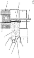
- the fuel injection device shown can also be used for an internal combustion engine with intake manifold injection, as is shown in figure 2 is shown.
- the fuel is injected through the injector 2 into a common intake manifold 15 of a plurality of combustion chambers 1 or into an inlet port of the combustion chamber 1 .
- the fuel/air mixture is generated in the intake manifold 15 or the intake port and fed to the combustion chamber 1 .
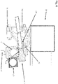
- FIG 3 shows a bottom view of an air distributor 30 for an internal combustion engine.
- the air distributor 30 shown here is mounted with its side 31 on the internal combustion engine or on the cylinder head 52 and, in the embodiment shown, supplies six combustion chambers 1 of the internal combustion engine, for example.
- the charge air flows out of the air distributor 30 into a respective inlet channel 52a of the internal combustion engine or of the cylinder head 52, which is identified here by the reference numeral 33a as an example.
- the individual feed tubes 32 serve to supply fuel into an inlet channel 52a from the central rail 10 directly attached to the air distributor 30.
- the gas connection or the fuel connection of the central rail 10 to the primary fuel path 12 is indicated with the reference number 17.
- the indicated exit of fuel from a feed tube 32 is shown as an example with an arrow 34 .
- the cylinder-specific supply tubes 32 each extend, starting from the end of the injector 2 protruding into the central rail 10, through the air distributor 30 and into the inlet channel 52a. In the figure 3 The installation position of the injectors 2 is only partially visible, because the component ends of the injectors 2 that are outside the central rail 10 are covered by the additional fuel pressure accumulator 20 in this view.
- the central rail 10 is attached to the housing wall of the air distributor 30 opposite the wall 31 . Cast-on sockets on the central rail 10 are used for the screw connection between the air distributor 30 and the central rail 10.
- the gas connection of the central rail 10 to the primary fuel path 12 is indicated with the reference number 17.
- the additional fuel pressure accumulator 20 is mounted behind the central rail 10 . It can be seen here that the fluid connection between these two inner volumes extends along correspondingly aligned openings in the housing walls.
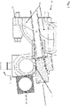
- the representation of figure 4 shows a view of the air distributor 30, which is turned away from the internal combustion engine in relation to an attached air distributor 30. In the illustration, only five injectors 2 have so far been installed in the corresponding installation openings of the central rail 10, with the second injector from the left only being placed at one installation location, but not yet fixed.
- the required fluid paths between the central rail 10 and additional fuel pressure accumulator 20 are reduced to a minimum, so that in the event of a highly dynamic increase in the required fuel supply quantity in the combustion chambers 1 within a very short period of time additional amount of fuel from the additional fuel pressure accumulator 20 can be provided.
- FIGS. 5 to 7 are sectional views of the exemplary embodiment, in which the arrangement and some of the fluid connections of the components that are particularly in focus can be seen.
- These include the central rail 10, the additional fuel pressure accumulator 20, the air distributor 30 and a fuel injector 2 as well as its reaching into the recess present in the cylinder head 52, which forms the inlet channel 52a there.
- figure 5 shows a section through the internal combustion engine, parts that are not essential to the invention being shown only schematically. the figure 5 however, serves to visualize the exemplary embodiment in relation to the installation position of the air distributor 30, the central rail 10 and the additional fuel pressure accumulator 20 on the internal combustion engine.
- the figures 6 , 7 are respective enlargements of the relevant interface area.
- the engine block 51 houses the liner 53, which in turn houses the piston 57.
- the cylinder head cover 58 is located above the cylinder head 52. Apart from the indicated spark plug 56 and a valve tappet 55, the components located below the cylinder head cover are not shown because they are not shown in the Focus of the invention are.
- the flow path of the air-fuel mixture along the inlet channel 52a to the combustion chamber is respectively opened and closed in a defined manner by means of the valve tappet 55 .
- the fluid connection between the inner volume of the central rail 10 and the injector 2 can still be seen in the enlarged illustrations.
- the injector 2 has a circumferential annular groove with a row of radial bores figure 7 are recognizable, through which the fuel can penetrate from the central rail 10 into the injector 2 and can be injected via the supply tube 32 into the inlet channel 52a.
- Precise coordination of these opening and closing interval times of the control valve 13 is implemented by an actuator system, with the corresponding coordination preferably being undertaken by a control unit which can be specified by a corresponding actuator system with knowledge of certain engine parameters and operating variables.
- Examples of such possible operating variables are the current one Rail pressure actual value, the actual crankshaft speed, the target value of the fuel injection that can actually be carried out, the desired value of the fuel injection (ie the amount of fuel under whose availability and usability in the combustion chamber the requested output power could be provided), the switching timing of the control valve 13, etc.
- the control unit or another control unit networked with it takes on coordination with the operating state of the air section by recording certain operating parameters of the air section (e.g.
- the control unit can determine the degrees of freedom of the internal combustion engine under the given current conditions - for example, the actual and target operating point of the speed-torque trajectory, the actual and target value of the rail pressure, the actual pressure in the additional fuel pressure accumulator 20, the operating state of the air path are called - use in order to achieve the best possible utilization of the fuel quantity available in the additional fuel pressure accumulator 20.
- the additional fuel pressure accumulator 20 only contains very little fuel - ie the level of fuel in it is comparatively low - or the additional fuel pressure accumulator 20 only contains ambient air because the safety concept provides for flushing with air the invention can clearly not yet be used. Provision could be made here for the user to be informed that the functional capability of the boost function, ie the functional capability of the invention, is only achieved through temporary high-load operation, which only needs to be of a very short duration.
- the system according to the invention is preferably suitable for the use of dynamically operated gas engines and particularly preferably for hydrogen engines.
- the system according to the invention is particularly suitable for gas engines that are used in mobile applications, e.g. road vehicles, mobile work machines, etc.
- a system according to the invention is particularly advantageous for hydrogen engines because gaseous hydrogen has a particularly low volumetric energy density compared to all other fuels.
- a corresponding increase in the internal volume of the rail or central rail is disadvantageous because if the mechanical power output required by the hydrogen engine decreases and the rail pressure is reduced, the amount of hydrogen to be removed from the rail increases accordingly. a diesel-like fuel etc. cannot simply be returned to the primary fuel tank.
Landscapes
- Engineering & Computer Science (AREA)
- Chemical & Material Sciences (AREA)
- Combustion & Propulsion (AREA)
- Mechanical Engineering (AREA)
- General Engineering & Computer Science (AREA)
- Chemical Kinetics & Catalysis (AREA)
- General Chemical & Material Sciences (AREA)
- Oil, Petroleum & Natural Gas (AREA)
- Analytical Chemistry (AREA)
- Fuel-Injection Apparatus (AREA)
Applications Claiming Priority (1)
| Application Number | Priority Date | Filing Date | Title |
|---|---|---|---|
| CH70041/21A CH718806A1 (de) | 2021-07-12 | 2021-07-12 | Kraftstoffeinspritzvorrichtung für eine Brennkraftmaschine, insbesondere für einen Wasserstoffverbrennungsmotor. |
Publications (2)
| Publication Number | Publication Date |
|---|---|
| EP4119785A1 true EP4119785A1 (fr) | 2023-01-18 |
| EP4119785B1 EP4119785B1 (fr) | 2025-09-10 |
Family
ID=82547103
Family Applications (1)
| Application Number | Title | Priority Date | Filing Date |
|---|---|---|---|
| EP22182101.0A Active EP4119785B1 (fr) | 2021-07-12 | 2022-06-30 | Dispositif d'injection de carburant pour un moteur à combustion interne, en particulier pour un moteur à combustion d'hydrogène |
Country Status (3)
| Country | Link |
|---|---|
| US (1) | US11885284B2 (fr) |
| EP (1) | EP4119785B1 (fr) |
| CH (1) | CH718806A1 (fr) |
Cited By (1)
| Publication number | Priority date | Publication date | Assignee | Title |
|---|---|---|---|---|
| WO2024256305A1 (fr) * | 2023-06-12 | 2024-12-19 | Daimler Truck AG | Dispositif d'injection pour moteur à gaz |
Families Citing this family (1)
| Publication number | Priority date | Publication date | Assignee | Title |
|---|---|---|---|---|
| CN119244403A (zh) * | 2024-09-30 | 2025-01-03 | 北京理工大学 | 一种基于气态高压储氢的氢气加压装置及方法 |
Citations (4)
| Publication number | Priority date | Publication date | Assignee | Title |
|---|---|---|---|---|
| WO2015169684A1 (fr) * | 2014-05-09 | 2015-11-12 | Robert Bosch Gmbh | Dispositif et procédé pour faire fonctionner un moteur à combustion interne avec un carburant gazeux |
| WO2018072839A1 (fr) * | 2016-10-21 | 2018-04-26 | Volvo Truck Corporation | Système de réservoir de gaz |
| WO2019048134A1 (fr) * | 2017-09-06 | 2019-03-14 | Robert Bosch Gmbh | Dispositif de refoulement de carburant pour moteur à combustion interne et procédé pour améliorer la capacité de démarrage pour un dispositif de refoulement de carburant |
| EP3741984A1 (fr) * | 2019-05-22 | 2020-11-25 | Liebherr Machines Bulle SA | Système de réservoirs pressurisés pour la fourniture de gaz |
Family Cites Families (16)
| Publication number | Priority date | Publication date | Assignee | Title |
|---|---|---|---|---|
| DE19547877A1 (de) * | 1995-12-21 | 1997-06-26 | Bosch Gmbh Robert | Kraftstoffhochdruckspeichersystem für ein in Brennkraftmaschinen eingesetztes Kraftstoffeinspritzsystem |
| DE19753072C2 (de) * | 1997-11-29 | 1999-11-18 | Bosch Gmbh Robert | Kraftstoffversorgungssystem für eine Brennkraftmaschine insbesondere eines Kraftfahrzeugs |
| DE19858095C2 (de) * | 1998-12-16 | 2000-10-19 | Siemens Ag | Vorrichtung zur Verbesserung des Startverhaltens von Verbrennungsmotoren mit Speichereinspritzsystemen |
| CA2538980C (fr) * | 2006-03-10 | 2008-09-23 | Westport Research Inc. | Methode et appareil de fonctionnement d'un moteur a combustion interne mixte |
| EP2180174B1 (fr) * | 2008-10-22 | 2012-01-25 | Delphi Technologies Holding S.à.r.l. | Agencement d'accumulateur de fluide pour moteur à combustion interne |
| DE102009028739A1 (de) * | 2009-08-20 | 2011-03-31 | Ford Global Technologies, LLC, Dearborn | Schnellstart eines Common Rail-Systems |
| DE102012224027A1 (de) * | 2012-12-20 | 2014-06-26 | Robert Bosch Gmbh | Kraftstoff-Einspritzsystem für eine Brennkraftmaschine |
| US9599082B2 (en) * | 2013-02-12 | 2017-03-21 | Ford Global Technologies, Llc | Direct injection fuel pump |
| US9308909B2 (en) * | 2013-06-06 | 2016-04-12 | Ford Global Technologies, Llc | Method and system for engine control |
| WO2015196244A1 (fr) * | 2014-06-25 | 2015-12-30 | Orbital Australia Pty Ltd | Ensemble rail de carburant |
| US10041435B2 (en) * | 2014-12-16 | 2018-08-07 | Fca Us Llc | Direct injection fuel system with controlled accumulator energy storage and delivery |
| US9638153B2 (en) * | 2015-02-20 | 2017-05-02 | Ford Global Technologies, Llc | Method for cooling a direct injection pump |
| US10100774B2 (en) * | 2015-06-25 | 2018-10-16 | Ford Global Technologies, Llc | Systems and methods for fuel injection |
| DE102017213120A1 (de) * | 2017-07-31 | 2019-01-31 | Bayerische Motoren Werke Aktiengesellschaft | Brennkraftmaschine mit einer Kraftstoffeinspritzung |
| US20190368449A1 (en) * | 2018-06-01 | 2019-12-05 | GM Global Technology Operations LLC | Returnless fuel system with accumulator |
| CH717258A1 (de) * | 2020-03-24 | 2021-09-30 | Liebherr Machines Bulle Sa | Vorrichtung zum Zuführen eines gasförmigen Kraftstoffs an einen Motor. |
-
2021
- 2021-07-12 CH CH70041/21A patent/CH718806A1/de not_active Application Discontinuation
-
2022
- 2022-06-30 EP EP22182101.0A patent/EP4119785B1/fr active Active
- 2022-07-11 US US17/861,821 patent/US11885284B2/en active Active
Patent Citations (4)
| Publication number | Priority date | Publication date | Assignee | Title |
|---|---|---|---|---|
| WO2015169684A1 (fr) * | 2014-05-09 | 2015-11-12 | Robert Bosch Gmbh | Dispositif et procédé pour faire fonctionner un moteur à combustion interne avec un carburant gazeux |
| WO2018072839A1 (fr) * | 2016-10-21 | 2018-04-26 | Volvo Truck Corporation | Système de réservoir de gaz |
| WO2019048134A1 (fr) * | 2017-09-06 | 2019-03-14 | Robert Bosch Gmbh | Dispositif de refoulement de carburant pour moteur à combustion interne et procédé pour améliorer la capacité de démarrage pour un dispositif de refoulement de carburant |
| EP3741984A1 (fr) * | 2019-05-22 | 2020-11-25 | Liebherr Machines Bulle SA | Système de réservoirs pressurisés pour la fourniture de gaz |
Cited By (1)
| Publication number | Priority date | Publication date | Assignee | Title |
|---|---|---|---|---|
| WO2024256305A1 (fr) * | 2023-06-12 | 2024-12-19 | Daimler Truck AG | Dispositif d'injection pour moteur à gaz |
Also Published As
| Publication number | Publication date |
|---|---|
| CH718806A1 (de) | 2023-01-13 |
| US20230019785A1 (en) | 2023-01-19 |
| US11885284B2 (en) | 2024-01-30 |
| EP4119785B1 (fr) | 2025-09-10 |
Similar Documents
| Publication | Publication Date | Title |
|---|---|---|
| EP1797297B1 (fr) | Procede et dispositif d'augmentation du couple d'un moteur alternatif a combustion interne, en particulier d'un moteur diesel | |
| EP2167799B1 (fr) | Procédé et dispositif pour augmenter la puissance de freinage moteur d'un moteur à combustion interne à piston alternatif dans un véhicule, en particulier d'un moteur diesel | |
| EP3029301B1 (fr) | Procede et systeme de fonctionnement d'au moins une unite fonctionnelle d'un vehicule automobile | |
| EP3885640A2 (fr) | Dispositif d'alimentation d'un moteur en un carburant gazeux | |
| DE69918589T2 (de) | Kraftstoffeinspritzsystem | |
| EP4119785B1 (fr) | Dispositif d'injection de carburant pour un moteur à combustion interne, en particulier pour un moteur à combustion d'hydrogène | |
| EP4245975A1 (fr) | Moteur à combustion interne à gaz à récupération de gaz combustible | |
| EP2876275B1 (fr) | Moteur à combustion interne à piston élévateur et procédé de fonctionnement d'un moteur à combustion interne à piston élévateur | |
| DE102014006533A1 (de) | Dual-Brennstoffmotorsystem und Motorsystembetriebsverfahren | |
| EP0946828B1 (fr) | Systeme d'injection de carburant d'un moteur a combustion interne | |
| EP2010983A2 (fr) | Régulateur de pression pour des substances gazeuses | |
| WO2017174118A1 (fr) | Systeme d'échange de carburant et de refoulement de carburant pour systèmes d'alimentation en carburant | |
| DE102019129982A1 (de) | System und verfahren zur ventilsitzeinspritzung | |
| DE10303573B4 (de) | Verfahren, Computerprogramm, Speichermedium und Steuer- und/oder Regelgerät zum Betreiben einer Brennkraftmaschine, sowie Brennkraftmaschine insbesondere für ein Kraftfahrzeug | |
| DE69415140T2 (de) | STEUERSYSTEM FüR EIN HOCHDRUCK-KRAFTSTOFFEINSPRITZSYSTEM FüR EINE BRENNKRAFTMASCHINE | |
| EP1361359B1 (fr) | Dispositif d'injection de carburant pour moteurs à combustion interne | |
| AT408137B (de) | Einrichtung zum einbringen von kraftstoff in den brennraum einer brennkraftmaschine | |
| EP4191044B1 (fr) | Procédé de fonctionnement d'un moteur à combustion interne doté d'un carburant gazeux et moteur à combustion interne | |
| EP4191036A1 (fr) | Procédé de fonctionnement d'un moteur à combustion interne suralimenté et dispositif de fourniture d'air de combustion pour un moteur à combustion interne suralimenté | |
| DE10346920B4 (de) | Motor mit einem System zur Kraftstoffsteuerung von Einspritzeinrichtungen und Verfahren dafür | |
| DE10315318A1 (de) | Verfahren zum Betreiben einer Brennkraftmaschine | |
| EP0923669A1 (fr) | Fonctionnement d'un moteur a combustion interne, notamment d'automobile | |
| DE102011076472B4 (de) | Schmierölzuführvorrichtung für eine brennkraftmaschine | |
| AT514107B1 (de) | Kraftstoffversorgungsanlage | |
| DE102010031356A1 (de) | Hochdruck-Einspritzsystem für Kraftstoff-Verbrennungsmaschinen |
Legal Events
| Date | Code | Title | Description |
|---|---|---|---|
| PUAI | Public reference made under article 153(3) epc to a published international application that has entered the european phase |
Free format text: ORIGINAL CODE: 0009012 |
|
| STAA | Information on the status of an ep patent application or granted ep patent |
Free format text: STATUS: THE APPLICATION HAS BEEN PUBLISHED |
|
| AK | Designated contracting states |
Kind code of ref document: A1 Designated state(s): AL AT BE BG CH CY CZ DE DK EE ES FI FR GB GR HR HU IE IS IT LI LT LU LV MC MK MT NL NO PL PT RO RS SE SI SK SM TR |
|
| STAA | Information on the status of an ep patent application or granted ep patent |
Free format text: STATUS: REQUEST FOR EXAMINATION WAS MADE |
|
| 17P | Request for examination filed |
Effective date: 20230714 |
|
| STAA | Information on the status of an ep patent application or granted ep patent |
Free format text: STATUS: EXAMINATION IS IN PROGRESS |
|
| 17Q | First examination report despatched |
Effective date: 20240625 |
|
| GRAP | Despatch of communication of intention to grant a patent |
Free format text: ORIGINAL CODE: EPIDOSNIGR1 |
|
| STAA | Information on the status of an ep patent application or granted ep patent |
Free format text: STATUS: GRANT OF PATENT IS INTENDED |
|
| INTG | Intention to grant announced |
Effective date: 20250508 |
|
| GRAS | Grant fee paid |
Free format text: ORIGINAL CODE: EPIDOSNIGR3 |
|
| GRAA | (expected) grant |
Free format text: ORIGINAL CODE: 0009210 |
|
| STAA | Information on the status of an ep patent application or granted ep patent |
Free format text: STATUS: THE PATENT HAS BEEN GRANTED |
|
| AK | Designated contracting states |
Kind code of ref document: B1 Designated state(s): AL AT BE BG CH CY CZ DE DK EE ES FI FR GB GR HR HU IE IS IT LI LT LU LV MC MK MT NL NO PL PT RO RS SE SI SK SM TR |
|
| REG | Reference to a national code |
Ref country code: GB Ref legal event code: FG4D Free format text: NOT ENGLISH |
|
| REG | Reference to a national code |
Ref country code: CH Ref legal event code: EP |
|
| REG | Reference to a national code |
Ref country code: DE Ref legal event code: R096 Ref document number: 502022005384 Country of ref document: DE |
|
| REG | Reference to a national code |
Ref country code: IE Ref legal event code: FG4D Free format text: LANGUAGE OF EP DOCUMENT: GERMAN |
|
| PG25 | Lapsed in a contracting state [announced via postgrant information from national office to epo] |
Ref country code: NO Free format text: LAPSE BECAUSE OF FAILURE TO SUBMIT A TRANSLATION OF THE DESCRIPTION OR TO PAY THE FEE WITHIN THE PRESCRIBED TIME-LIMIT Effective date: 20251210 |
|
| REG | Reference to a national code |
Ref country code: LT Ref legal event code: MG9D |
|
| PG25 | Lapsed in a contracting state [announced via postgrant information from national office to epo] |
Ref country code: FI Free format text: LAPSE BECAUSE OF FAILURE TO SUBMIT A TRANSLATION OF THE DESCRIPTION OR TO PAY THE FEE WITHIN THE PRESCRIBED TIME-LIMIT Effective date: 20250910 |
|
| REG | Reference to a national code |
Ref country code: NL Ref legal event code: MP Effective date: 20250910 |
|
| PG25 | Lapsed in a contracting state [announced via postgrant information from national office to epo] |
Ref country code: HR Free format text: LAPSE BECAUSE OF FAILURE TO SUBMIT A TRANSLATION OF THE DESCRIPTION OR TO PAY THE FEE WITHIN THE PRESCRIBED TIME-LIMIT Effective date: 20250910 |
|
| PG25 | Lapsed in a contracting state [announced via postgrant information from national office to epo] |
Ref country code: GR Free format text: LAPSE BECAUSE OF FAILURE TO SUBMIT A TRANSLATION OF THE DESCRIPTION OR TO PAY THE FEE WITHIN THE PRESCRIBED TIME-LIMIT Effective date: 20251211 |
|
| PG25 | Lapsed in a contracting state [announced via postgrant information from national office to epo] |
Ref country code: SE Free format text: LAPSE BECAUSE OF FAILURE TO SUBMIT A TRANSLATION OF THE DESCRIPTION OR TO PAY THE FEE WITHIN THE PRESCRIBED TIME-LIMIT Effective date: 20250910 |
|
| PG25 | Lapsed in a contracting state [announced via postgrant information from national office to epo] |
Ref country code: LV Free format text: LAPSE BECAUSE OF FAILURE TO SUBMIT A TRANSLATION OF THE DESCRIPTION OR TO PAY THE FEE WITHIN THE PRESCRIBED TIME-LIMIT Effective date: 20250910 |
|
| PG25 | Lapsed in a contracting state [announced via postgrant information from national office to epo] |
Ref country code: BG Free format text: LAPSE BECAUSE OF FAILURE TO SUBMIT A TRANSLATION OF THE DESCRIPTION OR TO PAY THE FEE WITHIN THE PRESCRIBED TIME-LIMIT Effective date: 20250910 Ref country code: PL Free format text: LAPSE BECAUSE OF FAILURE TO SUBMIT A TRANSLATION OF THE DESCRIPTION OR TO PAY THE FEE WITHIN THE PRESCRIBED TIME-LIMIT Effective date: 20250910 |
|
| PG25 | Lapsed in a contracting state [announced via postgrant information from national office to epo] |
Ref country code: RS Free format text: LAPSE BECAUSE OF FAILURE TO SUBMIT A TRANSLATION OF THE DESCRIPTION OR TO PAY THE FEE WITHIN THE PRESCRIBED TIME-LIMIT Effective date: 20251210 |
|
| PG25 | Lapsed in a contracting state [announced via postgrant information from national office to epo] |
Ref country code: ES Free format text: LAPSE BECAUSE OF FAILURE TO SUBMIT A TRANSLATION OF THE DESCRIPTION OR TO PAY THE FEE WITHIN THE PRESCRIBED TIME-LIMIT Effective date: 20250910 |
|
| PG25 | Lapsed in a contracting state [announced via postgrant information from national office to epo] |
Ref country code: NL Free format text: LAPSE BECAUSE OF FAILURE TO SUBMIT A TRANSLATION OF THE DESCRIPTION OR TO PAY THE FEE WITHIN THE PRESCRIBED TIME-LIMIT Effective date: 20250910 |
|
| PG25 | Lapsed in a contracting state [announced via postgrant information from national office to epo] |
Ref country code: SM Free format text: LAPSE BECAUSE OF FAILURE TO SUBMIT A TRANSLATION OF THE DESCRIPTION OR TO PAY THE FEE WITHIN THE PRESCRIBED TIME-LIMIT Effective date: 20250910 |
|
| PG25 | Lapsed in a contracting state [announced via postgrant information from national office to epo] |
Ref country code: IT Free format text: LAPSE BECAUSE OF FAILURE TO SUBMIT A TRANSLATION OF THE DESCRIPTION OR TO PAY THE FEE WITHIN THE PRESCRIBED TIME-LIMIT Effective date: 20250910 |
|
| PG25 | Lapsed in a contracting state [announced via postgrant information from national office to epo] |
Ref country code: IS Free format text: LAPSE BECAUSE OF FAILURE TO SUBMIT A TRANSLATION OF THE DESCRIPTION OR TO PAY THE FEE WITHIN THE PRESCRIBED TIME-LIMIT Effective date: 20260110 |
|
| PG25 | Lapsed in a contracting state [announced via postgrant information from national office to epo] |
Ref country code: CZ Free format text: LAPSE BECAUSE OF FAILURE TO SUBMIT A TRANSLATION OF THE DESCRIPTION OR TO PAY THE FEE WITHIN THE PRESCRIBED TIME-LIMIT Effective date: 20250910 Ref country code: PT Free format text: LAPSE BECAUSE OF FAILURE TO SUBMIT A TRANSLATION OF THE DESCRIPTION OR TO PAY THE FEE WITHIN THE PRESCRIBED TIME-LIMIT Effective date: 20260112 |
|
| PG25 | Lapsed in a contracting state [announced via postgrant information from national office to epo] |
Ref country code: SK Free format text: LAPSE BECAUSE OF FAILURE TO SUBMIT A TRANSLATION OF THE DESCRIPTION OR TO PAY THE FEE WITHIN THE PRESCRIBED TIME-LIMIT Effective date: 20250910 Ref country code: EE Free format text: LAPSE BECAUSE OF FAILURE TO SUBMIT A TRANSLATION OF THE DESCRIPTION OR TO PAY THE FEE WITHIN THE PRESCRIBED TIME-LIMIT Effective date: 20250910 |