EP4119817B1 - Anordnung zur schmierung eines getriebes - Google Patents
Anordnung zur schmierung eines getriebes Download PDFInfo
- Publication number
- EP4119817B1 EP4119817B1 EP21185795.8A EP21185795A EP4119817B1 EP 4119817 B1 EP4119817 B1 EP 4119817B1 EP 21185795 A EP21185795 A EP 21185795A EP 4119817 B1 EP4119817 B1 EP 4119817B1
- Authority
- EP
- European Patent Office
- Prior art keywords
- gear
- axial
- shoulder
- lubricant
- discontinuities
- Prior art date
- Legal status (The legal status is an assumption and is not a legal conclusion. Google has not performed a legal analysis and makes no representation as to the accuracy of the status listed.)
- Active
Links
Images






Classifications
-
- F—MECHANICAL ENGINEERING; LIGHTING; HEATING; WEAPONS; BLASTING
- F16—ENGINEERING ELEMENTS AND UNITS; GENERAL MEASURES FOR PRODUCING AND MAINTAINING EFFECTIVE FUNCTIONING OF MACHINES OR INSTALLATIONS; THERMAL INSULATION IN GENERAL
- F16H—GEARING
- F16H57/00—General details of gearing
- F16H57/04—Features relating to lubrication or cooling or heating
- F16H57/048—Type of gearings to be lubricated, cooled or heated
- F16H57/0482—Gearings with gears having orbital motion
- F16H57/0484—Gearings with gears having orbital motion with variable gear ratio or for reversing rotary motion
-
- F—MECHANICAL ENGINEERING; LIGHTING; HEATING; WEAPONS; BLASTING
- F16—ENGINEERING ELEMENTS AND UNITS; GENERAL MEASURES FOR PRODUCING AND MAINTAINING EFFECTIVE FUNCTIONING OF MACHINES OR INSTALLATIONS; THERMAL INSULATION IN GENERAL
- F16H—GEARING
- F16H57/00—General details of gearing
- F16H57/04—Features relating to lubrication or cooling or heating
- F16H57/042—Guidance of lubricant
- F16H57/0421—Guidance of lubricant on or within the casing, e.g. shields or baffles for collecting lubricant, tubes, pipes, grooves, channels or the like
- F16H57/0426—Means for guiding lubricant into an axial channel of a shaft
-
- F—MECHANICAL ENGINEERING; LIGHTING; HEATING; WEAPONS; BLASTING
- F16—ENGINEERING ELEMENTS AND UNITS; GENERAL MEASURES FOR PRODUCING AND MAINTAINING EFFECTIVE FUNCTIONING OF MACHINES OR INSTALLATIONS; THERMAL INSULATION IN GENERAL
- F16H—GEARING
- F16H57/00—General details of gearing
- F16H57/04—Features relating to lubrication or cooling or heating
- F16H57/042—Guidance of lubricant
- F16H57/043—Guidance of lubricant within rotary parts, e.g. axial channels or radial openings in shafts
- F16H57/0431—Means for guiding lubricant directly onto a tooth surface or to foot areas of a gear, e.g. by holes or grooves in a tooth flank
-
- F—MECHANICAL ENGINEERING; LIGHTING; HEATING; WEAPONS; BLASTING
- F16—ENGINEERING ELEMENTS AND UNITS; GENERAL MEASURES FOR PRODUCING AND MAINTAINING EFFECTIVE FUNCTIONING OF MACHINES OR INSTALLATIONS; THERMAL INSULATION IN GENERAL
- F16H—GEARING
- F16H57/00—General details of gearing
- F16H57/04—Features relating to lubrication or cooling or heating
- F16H57/0467—Elements of gearings to be lubricated, cooled or heated
-
- F—MECHANICAL ENGINEERING; LIGHTING; HEATING; WEAPONS; BLASTING
- F16—ENGINEERING ELEMENTS AND UNITS; GENERAL MEASURES FOR PRODUCING AND MAINTAINING EFFECTIVE FUNCTIONING OF MACHINES OR INSTALLATIONS; THERMAL INSULATION IN GENERAL
- F16H—GEARING
- F16H57/00—General details of gearing
- F16H57/04—Features relating to lubrication or cooling or heating
- F16H57/0467—Elements of gearings to be lubricated, cooled or heated
- F16H57/0479—Gears or bearings on planet carriers
-
- F—MECHANICAL ENGINEERING; LIGHTING; HEATING; WEAPONS; BLASTING
- F16—ENGINEERING ELEMENTS AND UNITS; GENERAL MEASURES FOR PRODUCING AND MAINTAINING EFFECTIVE FUNCTIONING OF MACHINES OR INSTALLATIONS; THERMAL INSULATION IN GENERAL
- F16H—GEARING
- F16H57/00—General details of gearing
- F16H57/04—Features relating to lubrication or cooling or heating
- F16H57/048—Type of gearings to be lubricated, cooled or heated
- F16H57/0482—Gearings with gears having orbital motion
Definitions
- the invention relates to an arrangement for lubricating gears in transmission gearing, said arrangement including at least one conduit which is intended to deliver lubricant under pressure, and which has an outlet orifice is located adjacent the gear to be lubricated.
- a planetary gearing comprises a component in the form of a ring gear provided with internal splines substantially matching the profile of the teeth on the sun gear. The tips of the splines are terminated before the root section between adjacent teeth on the sun gear. This allows lubricant under pressure to flow in ducts from a central supply duct in the main shaft, radially outwards to the internal splines on the ring gear and towards the meshing teeth between the sun gear and the planetary gears of the planetary gearing.
- a problem with this arrangement is that the manufacturing of such components will be relatively complicated and therefore expensive and time consuming. Also, the mounting of the component and the sealing of the ducts supplying lubricant will be relatively complex.
- the object of the invention is to provide an improved arrangement for lubricating gears that solves the above problems relating to lubrication and cooling of gears under heavy loads, as well as providing an arrangement that is more cost effective to manufacture and easier to assemble.
- vehicle is intended to describe any type of land-based vehicle, airborne vehicles or marine vessel that can comprise a transmission provided with a lubricating arrangement according to the claims.
- the arrangement is suitable for toothed gearings in general.
- the claimed arrangement is intended for use in connection with transmissions comprising toothed gearings requiring a continuous flow of lubricant to provide both lubrication and cooling to a set of meshing teeth between cooperating gears.
- This type of lubrication arrangement is particularly suited for a transmission under heavy loading.
- a typical example of such a transmission is a gearbox comprising a planetary gearing, as described in the published application WO 2011/069526 A1 .
- the operation of a planetary gearbox is described in detail in this document. Examples of how the arrangement can be applied is described below with reference to such a planetary gearing.
- EP1633998A1 discloses an arrangement according to the preamble of claim 1.
- the invention relates to an arrangement for lubricating a gear in a toothed gearing as defined in claim 1.
- a non-exclusive list of toothed gearings for which the arrangement is applicable includes vehicle transmissions, in particular heavy-duty transmissions and transmissions for marine vessels, in particular vessels comprising an in-board power unit with a transmission.
- Arrangements for lubricating gears in a toothed gearing are commonly connected to a supply of lubricant under pressure.
- a source of pressure such as a suitable pump can supply lubricant to the arrangement directly or via a pressurized tank.
- Lubricant can be directed to desired locations by means of individual conduits in the form of pipes or by using conduits within rotating shafts or shafts within a transmission.
- Such means for supplying lubricant under pressure are well known in the art and will not be described in further detail.
- the toothed gearing is a planetary gearing in a vehicle transmission and the component comprising a central annular portion is an engaging ring of the planetary gearing.
- the annular portion of the component is press-fitted onto the shoulder on the gear.
- the gear in this example is a sun gear in said planetary gearing.
- the shoulder has a diameter greater than the root circle of the gear. This can be achieved by machining the teeth of the sun gear at an end portion thereof until a portion of the root section between adjacent teeth remain.
- the axial discontinuities or recesses are formed by axial extensions of roots between each gear tooth and extend axially along the length of the peripheral surface of the shoulder. The discontinuities form recesses for guiding and distributing lubricant to the roots of the sun gear.
- the outer peripheral surface of the shoulder can comprise an undercut adjacent the teeth of the lubricated gear.
- the undercut is a circumferential undercut or groove that has been machined into the shoulder adjacent the teeth of the sun gear to be lubricated.
- the undercut provides stress relief and eliminates the risk of cracks forming at the transition between the shoulder and the teeth of the sun gear.
- the undercut also facilitates mounting of the annular portion of the ring gear flush against a radial surface formed by the end of the teeth of the sun gear.
- the depth of an outer portion of the axial discontinuities forming recesses for guiding and distributing lubricant to the roots of the gear increases in the direction of the component.
- the increase in depth is achieved by machining the outer end of each axial discontinuity, providing it with an angled surface that slopes radially inwards in the direction of the free end of the shoulder.
- This arrangement increases the cross-sectional surface area of the outer portion of the axial discontinuity, which causes an increase of the area at the opening the axial discontinuity where lubricant under pressure is supplied.
- the increased area will in turn cause an increased flow rate of the lubricant into the axial discontinuity.
- An effect of the increased flow rate is that the velocity of the lubricant will increase when the lubricant reaches the portion of the axial discontinuity that has not been machined.
- the width of an outer portion of the axial discontinuities forming recesses for guiding and distributing lubricant to the roots of the gear increases in the direction of the component.
- the increase in width is achieved by machining the outer end of each axial discontinuity, providing it with a pair of opposed angled side surfaces that diverge outwards in the direction of the free end of the shoulder.
- this arrangement increases the cross-sectional surface area of the outer portion of the axial discontinuity, which causes an increase of the area at the opening the axial discontinuity where lubricant under pressure is supplied.
- the increased area will in turn cause an increased flow rate of the lubricant into the axial discontinuity.
- An effect of the increased flow rate is that the velocity of the lubricant will increase when the lubricant reaches the portion of the axial discontinuity that has not been machined.
- both the width and the depth of an outer portion of the axial discontinuities increase in the direction of the component. Combining the above examples will contribute to a further increase in the flow rate of the lubricant into the axial discontinuity, and an increase in the velocity of the lubricant reaching the gear teeth.
- the invention relates to a vehicle comprising a transmission with a lubrication arrangement as described above.
- the ring component can according to one example simply be provided with an annular portion that can be press-fitted onto a shoulder of the sun gear.
- the ring gear can be made without the need for machining splines and reducing the number of seals required for lubricating ducts.
- the sun gear merely needs to be machined at one end to provide a shoulder having suitable dimensions for fitting the annular portion of the ring component.
- a further advantage is that the arrangement of the axial discontinuities allows them to be modified for different embodiments of a gearbox.
- a type of gearbox requires an increased amount of lubricant for, e.g. the planetary gearing, then the entrance portions of the axial discontinuities in the shoulder of the sun gear can be modified to provide an enlarged cross-sectional area.
- FIG. 1 shows a schematically indicated vehicle 101 with a transmission comprising a lubrication arrangement according to the invention.
- the vehicle 101 is provided with an internal combustion engine (ICE) 102 connected to a transmission with a gearbox 103, such as an automated manual transmission (AMT), for transmitting torque to a vehicle drive shaft (not shown).
- the lubrication arrangement is arranged to lubricate at least one gear in a toothed gearing inside the gearbox 103.
- the ICE 102 is connected to a radiator arrangement 104 for cooling engine coolant and oil from the ICE 102.
- the gearbox 103 is controlled by the driver or automatically via an electronic control unit (ECU) 105.
- the ECU 105 is provided with control algorithms for controlling the transmission independently during, for instance, an engine start requested by the driver.
- the transmission gearbox is controlled to select a gear ratio between the engine 102 and a pair of driven wheels 106.
- FIG. 2 shows a schematic diagram of a gearbox 200 comprising a lubrication arrangement according to the invention.
- the gearbox shown in Figure 2 is a stepped compound splitter and range transmission comprising a clutch 201, a splitter section 202, a main section 203 and a range section 204 with a planetary gear 205.
- the operation of such a gearbox is well known in the art and will not be described in further detail here.
- the subsequent examples describe a lubrication arrangement arranged to lubricate at least one gear in the planetary gear 205.
- the gearbox 200 is enclosed by an outer gearbox casing 206 which comprises transverse walls 207, 208 providing support for the rotary shafts of the different gearbox sections.
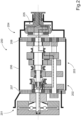
- FIG 3A shows a schematic cross-section of a planetary gear 300 in the range section 204 of a gearbox 200 as shown in Figure 2 .
- the planetary gear 300 comprises an input shaft or main shaft 301, which is the output shaft from the main section 203 shown in Figure 2 .
- An engaging ring 302 and a sun wheel 303 are rotatably fixed to the end of the main shaft 301 by means of axial splines or similar suitable fixing means.
- a central portion 312 of the engaging ring 302 is directly connected to the sun wheel 303, for instance by means of press-fitting.
- the sun wheel 303 is a central gear that is in driving connection with planet gears 304 rotatable about individual planet gear axles 305 supported by a planet carrier 306 that can be fixed to or, as shown in Figure 3A , part of a gearbox output shaft 307.
- the main shaft 301 and the gearbox output shaft 307 are arranged to rotate about a common axis X.
- the planetary gear 300 further comprises an outer ring gear 308 in driving connection with the planet gears 304.
- the outer ring gear 308 comprises teeth around its inner periphery and is displaceable in the axial direction of the planetary gear 300, in order to provide a low range mode or a high range mode of operation (see Figs.4A-4B ).
- the planetary gear 300 is enclosed by a casing 309 at one end of the gearbox casing 206 shown in Figure 2 .
- the gearbox output shaft 307 is supported by a bearing 310 relative to the casing 309 surrounding the planetary gear 300.
- Figure 3B shows a cross-section A-A through Figure 3A at right angles to the axis X of the main shaft 301.
- Figure 3B shows the central sun wheel 303 in driving contact with four planet gears 304 which are rotatable about their respective planet gear axles 305.
- the figure further shows the outer ring gear 308 in driving connection with each of the four planet gears 304.
- FIGs 4A and 4B show schematic cross-sections of a planetary gear 400 of the same type as described for Figure 3A .
- the planetary gear 400 comprises a main shaft 401 extending from the main section 203 shown in Figure 2 .
- An engaging ring 402 and a sun wheel 403 are rotatably fixed to the end of the main shaft 401.
- a central portion 412 of the engaging ring 402 is directly connected to the sun wheel 403, for instance by means of press-fitting.
- the sun wheel 403 is in driving connection with planet gears 404 rotatable about individual planet gear axles 405 supported by a planet carrier 406 that is part of a gearbox output shaft 407.
- the main shaft 401 and the gearbox output shaft 407 are arranged to rotate about a common axis X.
- the planetary gear 400 further comprises an outer ring gear 408 in driving connection with the planet gears 404.
- the outer ring gear 408 comprises teeth around its inner periphery and is displaceable in the axial direction of the planetary gear 400.
- the planetary gear 400 is enclosed by a casing 409 at one end of the gearbox casing 206 shown in Figure 2 .
- the gearbox output shaft 407 is supported by a bearing 410 relative to the casing 409 surrounding the planetary gear 400.
- Figure 4A shows the planetary gear 400 in a low range mode of operation.
- the ring gear 408 In the low range mode, the ring gear 408 is displaced into a first position as indicated by the arrow A. In the first position, the ring gear 408 is connected to the casing 409 and is fixed against rotation. Input torque from the main section of the gearbox (see Fig.2 ) causes rotation of the main shaft 401 and its sun wheel 403, which will in turn rotate the planet gears 404 relative to the non-rotating ring gear 408. Subsequently, the planet gear axles 405 supporting the planet gears 404 will rotate about the sun wheel 403 and cause a rotation of the planet carrier 406 and the gearbox output shaft 407. This mode of operation causes a speed reduction from the main shaft 401 to the gearbox output shaft 407.
- Figure 4B shows the planetary gear 400 in a high range mode of operation.
- the ring gear 408 In the high range mode, the ring gear 408 is displaced into a second position indicated by the arrow B. In the second position, the internal teeth of the ring gear 408 are connected to a toothed outer periphery (not shown) of the engaging ring 402 and is allowed to rotate with the main shaft 401.
- Input torque from the main section of the gearbox causes rotation of the main shaft 401, which will in turn rotate the engaging ring 402 and the planet gears 404.
- Figure 5A shows a schematic cross-section through a first example of an arrangement suitable for lubricating a toothed gearing such as a sun wheel 503 and a set of cooperating planetary wheels 504 in a planetary gear of the type described above.
- the planetary wheels 504 are mounted on shafts 505 supported on a planet carrier (not shown; see Fig.3A , "306").
- the arrangement in Figure 5A comprises a main shaft 501 on which the sun wheel 503 is fixed against rotation by means of cooperating splines 521 on the main shaft 501 and the sun wheel 503, respectively.
- the sun wheel 503 is fixed in a predetermined axial position on the main shaft 501 by means of a retaining nut 522 mounted at a threaded end section 523 of the main shaft 501.
- An engaging ring 502 is arranged on the opposite side of the sun wheel 503.
- a central portion 512 of the engaging ring 502 is fixed against rotation by means of cooperating splines 525 on the main shaft 501 and the central portion 512, respectively.
- the location and function of the engaging ring 502 has been described in connection with Figure 4A-B above.
- the central portion 512 of the engaging ring 502 can be located in a predetermined axial position on the main shaft 501 by a stepped section (not shown) provided on the main shaft 501.
- the central portion 512 is arranged around the main shaft 501 and comprises a radial surface 526 that is facing and spaced from an end surface 527 the sun gear 503.
- the central portion 512 further comprises an annular portion 528 with an inner peripheral surface 529.
- the annular portion 528 extends towards an outer peripheral surface 535 of a shoulder 530 on the sun gear 503.
- the annular portion 528 of the central portion 512 has an inner diameter less than the pitch circle of the sun gear 503.
- the annular portion 528 of the central portion 512 is fixed in position on the shoulder 530 of the sun gear 503 by press-fitting.
- the main shaft 501 comprises a central duct 531 for supplying lubricant under pressure, which central duct 531 is connected to a source of lubricant for the toothed gearing.
- the main shaft 501 further comprises a number of radial ducts 532 each having an opening in the outer periphery of the main shaft 501 in an area located in proximity to the sun gear 503. Specifically, the radial ducts 532 open up in a gap 533 between the facing radial surfaces 526, 527 of the central portion 512 and the sun gear 503, respectively.
- the gap 533 is arranged for guiding and distributing lubricant from the radial ducts 532 and radially outwards to the meshing teeth 540, 541 of the sun gear 503 and the planetary gears 504.
- the facing surfaces 526, 527 are shown as radial surfaces in Figure 5A for reasons of clarity. Alternative surfaces, such as concave, convex or conical facing surfaces can be used within the scope of the invention.
- the radial ducts 532 extending through the main shaft 501 can be arranged at any suitable angle within the scope of the invention.
- lubricant under pressure can be supplied from a suitable source and be supplied to the gap 533 through the splines on the main shaft 501 and the central portion 512, respectively.
- the flow of lubricant is indicated by a dashed arrow B'.
- axial discontinuities 534 are provided between the shoulder 530 on the sun gear 503 and the annular portion 528 of the central portion 512.
- the axial discontinuities 534 are arranged along the peripheral surface of the shoulder 530, which axial discontinuities 534 form axial recesses guiding and distributing lubricant to the roots of the teeth 540 of the sun gear 503.
- the axial discontinuities 534 are formed by machining a section of the sun gear 503 to remove an axial section of an outer portion of the gear teeth 540 when making the shoulder 530.
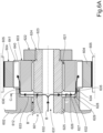
- Figure 6A shows a cross-section through a second example of an arrangement suitable for lubricating a toothed gearing such as a sun wheel 603 and a set of cooperating planetary wheels 604 in a planetary gear of the type described above.
- the planetary wheels 604 are mounted on shafts 605 supported on a planet carrier (not shown; see Fig.3A , "306").
- the arrangement in Figure 6A comprises a main shaft 601 on which the sun wheel 603 is fixed against rotation by means of cooperating splines 621 on the main shaft 601 and the sun wheel 603, respectively.
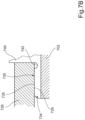
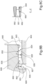
- Figures 8A-8C illustrate axial discontinuities in a shoulder of the type described in connection with the example in Figures 5A and 5B .
- the enlargement of the outer portion of the axial discontinuities 834 as shown in Figures 8B and 8C can also be used in a shoulder according to the example shown in Figures 6A and 6B , specifically for examples where the shoulder has been machined to leave a portion of the roots in the outer surface thereof.
Landscapes
- Engineering & Computer Science (AREA)
- General Engineering & Computer Science (AREA)
- Mechanical Engineering (AREA)
- General Details Of Gearings (AREA)
Claims (11)
- Anordnung zum Schmieren eines Zahnrads (503; 603; 703; 803) in einem Zahnradgetriebe, umfassend:- eine Welle (501; 601; 701; 801), auf der das Zahnrad (503; 603; 703; 803) angeordnet ist,- einen Eingriffsring (502; 602; 702; 802), der um die Welle (501; 601; 701; 801) herum angeordnet ist und eine Oberfläche (526; 626; 726; 826) umfasst, die einer Endoberfläche (527; 627; 727; 827) des Zahnrads (503; 603; 703; 803) zugewandt und von dieser beabstandet ist, wobei ein Spalt (533; 633; 733; 833) zum Leiten und Verteilen von Schmiermittel an das Zahnrad geschaffen wird,- mindestens einen ersten Kanal (531, 532; 525; 631, 632; 625; 731, 732; 725; 831, 832; 825) zum Zuführen von Schmiermittel unter Druck, wobei der Kanal mindestens eine Öffnung in den Spalt (533; 633; 733; 833) neben dem zu schmierenden Zahnrad (503; 603; 703; 803) aufweist,
wobeider Eingriffsring einen ringförmigen Abschnitt (528; 628; 728; 828) mit einer inneren Umfangsoberfläche umfasst, die auf einer äußeren Umfangsoberfläche einer Schulter (530; 630; 730; 830) auf dem Zahnrad montiert ist;wobei der ringförmige Abschnitt einen Innendurchmesser aufweist, der kleiner als der Teilkreis des Zahnrads ist; und wobei zwischen der Schulter (530; 630; 730; 830) und dem ringförmigen Abschnitt des Eingriffsrings axiale Diskontinuitäten (534; 634; 734; 834) bereitgestellt sind, wobei die Diskontinuitäten Vertiefungen zum Leiten und Verteilen von Schmiermittel zu den Wurzeln des Zahnrads (503; 603; 703; 803) ausbilden,
dadurch gekennzeichnet, dassder ringförmige Abschnitt des Eingriffsrings (502; 602; 702; 802) auf die Schulter (530; 630; 730; 830) an dem Zahnrad (503; 603; 703; 803) eingepresst ist. - Anordnung nach Anspruch 1, wobei der Eingriffsring (502; 602; 702; 802) ein Eingriffsring in einem Planetengetriebe ist.
- Anordnung nach einem der Ansprüche 1 bis 2, wobei das Zahnrad (503; 603; 703; 803) ein Sonnenrad in einem Planetengetriebe ist.
- Anordnung nach einem der Ansprüche 1 bis 3, wobei die Schulter (530; 630; 730; 830) einen Durchmesser aufweist, der größer als der Fußkreis des Zahnrads (503; 603; 703; 803) ist.
- Anordnung nach einem der Ansprüche 1 bis 4, wobei die axialen Diskontinuitäten (534; 634; 734; 834) axiale Verlängerungen von Wurzeln zwischen jedem Zahnradzahn des Zahnrads (503; 603; 703; 803) sind.
- Anordnung nach einem der Ansprüche 1 bis 5, wobei die Schulter (530; 730; 830) axiale Diskontinuitäten (534; 734; 834) entlang ihrer Umfangsoberfläche (535; 735; 835) aufweist, wobei die Diskontinuitäten Vertiefungen (534; 734; 834) zum Leiten und Verteilen von Schmiermittel an die Wurzeln des Zahnrads (503; 703; 803) ausbilden.
- Anordnung nach einem der Ansprüche 1 bis 6, wobei der ringförmige Abschnitt (628) des Eingriffsrings entlang seiner inneren Umfangsoberfläche axiale Diskontinuitäten (634) zum Leiten und Verteilen von Schmiermittel an die Wurzeln des Zahnrads (603) aufweist.
- Anordnung nach einem der Ansprüche 1 bis 7, wobei die äußere Umfangsoberfläche (735; 835) der Schulter (730; 830) einen Hinterschnitt (742; 842) neben den Zähnen (740; 840) des geschmierten Zahnrads (703; 803) umfasst.
- Anordnung nach einem der Ansprüche 1 bis 8, wobei die Breite eines äußeren Abschnitts (850) der axialen Diskontinuitäten (834), die Vertiefungen zum Leiten und Verteilen von Schmiermittel an die Wurzeln des Zahnrads (803) ausbilden, in Richtung des Eingriffsrings (802) zunimmt.
- Anordnung nach einem der Ansprüche 1 bis 9, wobei die Tiefe eines äußeren Abschnitts (850) der axialen Diskontinuitäten (834), die Vertiefungen zum Leiten und Verteilen von Schmiermittel an die Wurzeln des Zahnrads (803) ausbilden, in Richtung des Eingriffsrings (802) zunimmt.
- Fahrzeug, umfassend ein Getriebe mit einer Schmieranordnung nach Anspruch 1.
Priority Applications (4)
| Application Number | Priority Date | Filing Date | Title |
|---|---|---|---|
| EP21185795.8A EP4119817B1 (de) | 2021-07-15 | 2021-07-15 | Anordnung zur schmierung eines getriebes |
| US17/859,165 US11662015B2 (en) | 2021-07-15 | 2022-07-07 | Arrangement for lubricating a gear |
| CN202210814572.8A CN115614457A (zh) | 2021-07-15 | 2022-07-12 | 用于润滑齿轮的设备 |
| JP2022111725A JP2023014024A (ja) | 2021-07-15 | 2022-07-12 | 歯車を潤滑するための機構 |
Applications Claiming Priority (1)
| Application Number | Priority Date | Filing Date | Title |
|---|---|---|---|
| EP21185795.8A EP4119817B1 (de) | 2021-07-15 | 2021-07-15 | Anordnung zur schmierung eines getriebes |
Publications (2)
| Publication Number | Publication Date |
|---|---|
| EP4119817A1 EP4119817A1 (de) | 2023-01-18 |
| EP4119817B1 true EP4119817B1 (de) | 2025-01-29 |
Family
ID=76942878
Family Applications (1)
| Application Number | Title | Priority Date | Filing Date |
|---|---|---|---|
| EP21185795.8A Active EP4119817B1 (de) | 2021-07-15 | 2021-07-15 | Anordnung zur schmierung eines getriebes |
Country Status (4)
| Country | Link |
|---|---|
| US (1) | US11662015B2 (de) |
| EP (1) | EP4119817B1 (de) |
| JP (1) | JP2023014024A (de) |
| CN (1) | CN115614457A (de) |
Families Citing this family (4)
| Publication number | Priority date | Publication date | Assignee | Title |
|---|---|---|---|---|
| EP3974681A1 (de) * | 2020-09-29 | 2022-03-30 | Volvo Truck Corporation | Zahnradanordnung |
| US12152664B2 (en) * | 2022-10-31 | 2024-11-26 | Dana Heavy Vehicle Systems Group, Llc | Lubrication directing ring |
| EP4571148A1 (de) * | 2023-12-15 | 2025-06-18 | Volvo Truck Corporation | Anordnung zum schmieren eines zahnrades eines getriebes, getriebe und fahrzeug |
| US12460572B1 (en) * | 2024-08-06 | 2025-11-04 | Deere & Company | Gear shaft and internal combustion engine having a gear shaft |
Family Cites Families (9)
| Publication number | Priority date | Publication date | Assignee | Title |
|---|---|---|---|---|
| US5242033A (en) * | 1991-09-13 | 1993-09-07 | General Electric Company | High power gear cooling system |
| SE525207C2 (sv) * | 2003-05-28 | 2004-12-28 | Volvo Lastvagnar Ab | Anordning för smörjning av en kuggväxel |
| JP2007500326A (ja) | 2003-05-30 | 2007-01-11 | フオルクスワーゲン・アクチエンゲゼルシヤフト | ダブルクラッチトランスミッション |
| DE102008058949B4 (de) * | 2008-11-25 | 2014-07-03 | Getrag Ford Transmissions Gmbh | Getriebe mit Zahnrädern und Ölkanal |
| EP2510259B1 (de) | 2009-12-09 | 2015-12-02 | Volvo Lastvagnar AB | Lastschaltgetriebe für ein kraftfahrzeug |
| DE102010060147B4 (de) * | 2010-10-25 | 2017-03-09 | Eickhoff Antriebstechnik Gmbh | Planetengetriebe mit einem Zentralverteiler |
| DE102016102096A1 (de) * | 2016-02-05 | 2017-08-10 | Rolls-Royce Deutschland Ltd & Co Kg | Verzahnungskörper mit einer Schmiermittelzuführeinrichtung und Strahltriebwerk mit einem derartigen Verzahnungskörper |
| FR3084427B1 (fr) * | 2018-07-26 | 2021-03-12 | Safran Trans Systems | Dispositif de type reducteur mecanique pour une turbomachine |
| DE102019214843A1 (de) * | 2019-09-27 | 2021-04-01 | Zf Friedrichshafen Ag | Kraftfahrzeuggetriebe |
-
2021
- 2021-07-15 EP EP21185795.8A patent/EP4119817B1/de active Active
-
2022
- 2022-07-07 US US17/859,165 patent/US11662015B2/en active Active
- 2022-07-12 JP JP2022111725A patent/JP2023014024A/ja active Pending
- 2022-07-12 CN CN202210814572.8A patent/CN115614457A/zh active Pending
Also Published As
| Publication number | Publication date |
|---|---|
| US20230023243A1 (en) | 2023-01-26 |
| US11662015B2 (en) | 2023-05-30 |
| JP2023014024A (ja) | 2023-01-26 |
| EP4119817A1 (de) | 2023-01-18 |
| CN115614457A (zh) | 2023-01-17 |
Similar Documents
| Publication | Publication Date | Title |
|---|---|---|
| EP4119817B1 (de) | Anordnung zur schmierung eines getriebes | |
| US11143271B2 (en) | Cage for a turbomachine speed reducer with planetary gear set | |
| EP1435475B1 (de) | Lagerung für Planetenrad eines Planetengetriebes | |
| EP1488139B1 (de) | Schmierung einer getriebeeinheit | |
| US11976786B2 (en) | Oil restrictor for emergency lubrication of a component for an aircraft turbine engine | |
| CN110770476B (zh) | 用于涡轮机的周转或行星减速齿轮的圈形齿轮 | |
| US11242925B2 (en) | Ring gear for an epicyclic or planetary reduction gear of a turbomachine | |
| US20070175706A1 (en) | Positive lubrication of a meshing gear | |
| US5557980A (en) | One-piece gear rattle prevention for countershaft transmission | |
| CN115574074B (zh) | 一种高速行星齿轮箱离心式润滑油路系统 | |
| US11428310B2 (en) | Stepped spindle | |
| EP3936736B1 (de) | Innere kerbverzahnung mit feuerstegablaufloch | |
| US20230167857A1 (en) | Hollow-Shaft Assembly for a Motor Vehicle | |
| US20080060877A1 (en) | Oil Supply Device | |
| US20210254706A1 (en) | Rotary planet carrier for a mechanical reduction gear of a turbomachine | |
| US11754171B2 (en) | Gearwheel arrangement | |
| GB2166813A (en) | Tapered roller bearing assembly | |
| EP0424341B1 (de) | Schmiereinrichtung für ein Zahnrädergetriebe | |
| US12578010B2 (en) | Oil guiding component for an oil guiding arrangement | |
| US12429129B2 (en) | Assembly for lubricating a gearwheel of a transmission, a transmission and a vehicle | |
| US20260002521A1 (en) | Shaft-hub connection for a transmission | |
| US20260117856A1 (en) | Shaft-hub connection for a transmission | |
| CN112272734A (zh) | 用于涡轮机的减速器的旋转行星架的油分配装置 | |
| US20200271213A1 (en) | Transmission Shaft, Transmission, and Motor Vehicle Drivetrain | |
| GB2641234A (en) | Bearing sleeve |
Legal Events
| Date | Code | Title | Description |
|---|---|---|---|
| PUAI | Public reference made under article 153(3) epc to a published international application that has entered the european phase |
Free format text: ORIGINAL CODE: 0009012 |
|
| STAA | Information on the status of an ep patent application or granted ep patent |
Free format text: STATUS: THE APPLICATION HAS BEEN PUBLISHED |
|
| AK | Designated contracting states |
Kind code of ref document: A1 Designated state(s): AL AT BE BG CH CY CZ DE DK EE ES FI FR GB GR HR HU IE IS IT LI LT LU LV MC MK MT NL NO PL PT RO RS SE SI SK SM TR |
|
| STAA | Information on the status of an ep patent application or granted ep patent |
Free format text: STATUS: REQUEST FOR EXAMINATION WAS MADE |
|
| 17P | Request for examination filed |
Effective date: 20230711 |
|
| RBV | Designated contracting states (corrected) |
Designated state(s): AL AT BE BG CH CY CZ DE DK EE ES FI FR GB GR HR HU IE IS IT LI LT LU LV MC MK MT NL NO PL PT RO RS SE SI SK SM TR |
|
| GRAP | Despatch of communication of intention to grant a patent |
Free format text: ORIGINAL CODE: EPIDOSNIGR1 |
|
| STAA | Information on the status of an ep patent application or granted ep patent |
Free format text: STATUS: GRANT OF PATENT IS INTENDED |
|
| INTG | Intention to grant announced |
Effective date: 20241118 |
|
| GRAS | Grant fee paid |
Free format text: ORIGINAL CODE: EPIDOSNIGR3 |
|
| GRAA | (expected) grant |
Free format text: ORIGINAL CODE: 0009210 |
|
| STAA | Information on the status of an ep patent application or granted ep patent |
Free format text: STATUS: THE PATENT HAS BEEN GRANTED |
|
| AK | Designated contracting states |
Kind code of ref document: B1 Designated state(s): AL AT BE BG CH CY CZ DE DK EE ES FI FR GB GR HR HU IE IS IT LI LT LU LV MC MK MT NL NO PL PT RO RS SE SI SK SM TR |
|
| REG | Reference to a national code |
Ref country code: GB Ref legal event code: FG4D |
|
| REG | Reference to a national code |
Ref country code: CH Ref legal event code: EP |
|
| REG | Reference to a national code |
Ref country code: DE Ref legal event code: R096 Ref document number: 602021025313 Country of ref document: DE |
|
| REG | Reference to a national code |
Ref country code: IE Ref legal event code: FG4D |
|
| REG | Reference to a national code |
Ref country code: NL Ref legal event code: MP Effective date: 20250129 |
|
| PG25 | Lapsed in a contracting state [announced via postgrant information from national office to epo] |
Ref country code: NL Free format text: LAPSE BECAUSE OF FAILURE TO SUBMIT A TRANSLATION OF THE DESCRIPTION OR TO PAY THE FEE WITHIN THE PRESCRIBED TIME-LIMIT Effective date: 20250129 |
|
| PG25 | Lapsed in a contracting state [announced via postgrant information from national office to epo] |
Ref country code: RS Free format text: LAPSE BECAUSE OF FAILURE TO SUBMIT A TRANSLATION OF THE DESCRIPTION OR TO PAY THE FEE WITHIN THE PRESCRIBED TIME-LIMIT Effective date: 20250429 |
|
| PG25 | Lapsed in a contracting state [announced via postgrant information from national office to epo] |
Ref country code: FI Free format text: LAPSE BECAUSE OF FAILURE TO SUBMIT A TRANSLATION OF THE DESCRIPTION OR TO PAY THE FEE WITHIN THE PRESCRIBED TIME-LIMIT Effective date: 20250129 |
|
| PG25 | Lapsed in a contracting state [announced via postgrant information from national office to epo] |
Ref country code: PL Free format text: LAPSE BECAUSE OF FAILURE TO SUBMIT A TRANSLATION OF THE DESCRIPTION OR TO PAY THE FEE WITHIN THE PRESCRIBED TIME-LIMIT Effective date: 20250129 |
|
| PG25 | Lapsed in a contracting state [announced via postgrant information from national office to epo] |
Ref country code: ES Free format text: LAPSE BECAUSE OF FAILURE TO SUBMIT A TRANSLATION OF THE DESCRIPTION OR TO PAY THE FEE WITHIN THE PRESCRIBED TIME-LIMIT Effective date: 20250129 |
|
| REG | Reference to a national code |
Ref country code: LT Ref legal event code: MG9D |
|
| PG25 | Lapsed in a contracting state [announced via postgrant information from national office to epo] |
Ref country code: NO Free format text: LAPSE BECAUSE OF FAILURE TO SUBMIT A TRANSLATION OF THE DESCRIPTION OR TO PAY THE FEE WITHIN THE PRESCRIBED TIME-LIMIT Effective date: 20250429 Ref country code: IS Free format text: LAPSE BECAUSE OF FAILURE TO SUBMIT A TRANSLATION OF THE DESCRIPTION OR TO PAY THE FEE WITHIN THE PRESCRIBED TIME-LIMIT Effective date: 20250529 |
|
| REG | Reference to a national code |
Ref country code: AT Ref legal event code: MK05 Ref document number: 1763722 Country of ref document: AT Kind code of ref document: T Effective date: 20250129 |
|
| PG25 | Lapsed in a contracting state [announced via postgrant information from national office to epo] |
Ref country code: HR Free format text: LAPSE BECAUSE OF FAILURE TO SUBMIT A TRANSLATION OF THE DESCRIPTION OR TO PAY THE FEE WITHIN THE PRESCRIBED TIME-LIMIT Effective date: 20250129 |
|
| PG25 | Lapsed in a contracting state [announced via postgrant information from national office to epo] |
Ref country code: LV Free format text: LAPSE BECAUSE OF FAILURE TO SUBMIT A TRANSLATION OF THE DESCRIPTION OR TO PAY THE FEE WITHIN THE PRESCRIBED TIME-LIMIT Effective date: 20250129 Ref country code: PT Free format text: LAPSE BECAUSE OF FAILURE TO SUBMIT A TRANSLATION OF THE DESCRIPTION OR TO PAY THE FEE WITHIN THE PRESCRIBED TIME-LIMIT Effective date: 20250529 |
|
| PG25 | Lapsed in a contracting state [announced via postgrant information from national office to epo] |
Ref country code: GR Free format text: LAPSE BECAUSE OF FAILURE TO SUBMIT A TRANSLATION OF THE DESCRIPTION OR TO PAY THE FEE WITHIN THE PRESCRIBED TIME-LIMIT Effective date: 20250430 Ref country code: BG Free format text: LAPSE BECAUSE OF FAILURE TO SUBMIT A TRANSLATION OF THE DESCRIPTION OR TO PAY THE FEE WITHIN THE PRESCRIBED TIME-LIMIT Effective date: 20250129 |
|
| PG25 | Lapsed in a contracting state [announced via postgrant information from national office to epo] |
Ref country code: AT Free format text: LAPSE BECAUSE OF FAILURE TO SUBMIT A TRANSLATION OF THE DESCRIPTION OR TO PAY THE FEE WITHIN THE PRESCRIBED TIME-LIMIT Effective date: 20250129 |
|
| PG25 | Lapsed in a contracting state [announced via postgrant information from national office to epo] |
Ref country code: SE Free format text: LAPSE BECAUSE OF FAILURE TO SUBMIT A TRANSLATION OF THE DESCRIPTION OR TO PAY THE FEE WITHIN THE PRESCRIBED TIME-LIMIT Effective date: 20250129 |
|
| PG25 | Lapsed in a contracting state [announced via postgrant information from national office to epo] |
Ref country code: SM Free format text: LAPSE BECAUSE OF FAILURE TO SUBMIT A TRANSLATION OF THE DESCRIPTION OR TO PAY THE FEE WITHIN THE PRESCRIBED TIME-LIMIT Effective date: 20250129 |
|
| PG25 | Lapsed in a contracting state [announced via postgrant information from national office to epo] |
Ref country code: DK Free format text: LAPSE BECAUSE OF FAILURE TO SUBMIT A TRANSLATION OF THE DESCRIPTION OR TO PAY THE FEE WITHIN THE PRESCRIBED TIME-LIMIT Effective date: 20250129 |
|
| PGFP | Annual fee paid to national office [announced via postgrant information from national office to epo] |
Ref country code: DE Payment date: 20250728 Year of fee payment: 5 |
|
| PG25 | Lapsed in a contracting state [announced via postgrant information from national office to epo] |
Ref country code: IT Free format text: LAPSE BECAUSE OF FAILURE TO SUBMIT A TRANSLATION OF THE DESCRIPTION OR TO PAY THE FEE WITHIN THE PRESCRIBED TIME-LIMIT Effective date: 20250129 |
|
| PGFP | Annual fee paid to national office [announced via postgrant information from national office to epo] |
Ref country code: FR Payment date: 20250725 Year of fee payment: 5 |
|
| PG25 | Lapsed in a contracting state [announced via postgrant information from national office to epo] |
Ref country code: EE Free format text: LAPSE BECAUSE OF FAILURE TO SUBMIT A TRANSLATION OF THE DESCRIPTION OR TO PAY THE FEE WITHIN THE PRESCRIBED TIME-LIMIT Effective date: 20250129 Ref country code: CZ Free format text: LAPSE BECAUSE OF FAILURE TO SUBMIT A TRANSLATION OF THE DESCRIPTION OR TO PAY THE FEE WITHIN THE PRESCRIBED TIME-LIMIT Effective date: 20250129 |
|
| PG25 | Lapsed in a contracting state [announced via postgrant information from national office to epo] |
Ref country code: RO Free format text: LAPSE BECAUSE OF FAILURE TO SUBMIT A TRANSLATION OF THE DESCRIPTION OR TO PAY THE FEE WITHIN THE PRESCRIBED TIME-LIMIT Effective date: 20250129 |
|
| PG25 | Lapsed in a contracting state [announced via postgrant information from national office to epo] |
Ref country code: SK Free format text: LAPSE BECAUSE OF FAILURE TO SUBMIT A TRANSLATION OF THE DESCRIPTION OR TO PAY THE FEE WITHIN THE PRESCRIBED TIME-LIMIT Effective date: 20250129 |
|
| REG | Reference to a national code |
Ref country code: DE Ref legal event code: R097 Ref document number: 602021025313 Country of ref document: DE |
|
| PLBE | No opposition filed within time limit |
Free format text: ORIGINAL CODE: 0009261 |
|
| STAA | Information on the status of an ep patent application or granted ep patent |
Free format text: STATUS: NO OPPOSITION FILED WITHIN TIME LIMIT |
|
| REG | Reference to a national code |
Ref country code: CH Ref legal event code: L10 Free format text: ST27 STATUS EVENT CODE: U-0-0-L10-L00 (AS PROVIDED BY THE NATIONAL OFFICE) Effective date: 20251210 |
|
| 26N | No opposition filed |
Effective date: 20251030 |
|
| REG | Reference to a national code |
Ref country code: CH Ref legal event code: H13 Free format text: ST27 STATUS EVENT CODE: U-0-0-H10-H13 (AS PROVIDED BY THE NATIONAL OFFICE) Effective date: 20260224 |
|
| PG25 | Lapsed in a contracting state [announced via postgrant information from national office to epo] |
Ref country code: LU Free format text: LAPSE BECAUSE OF NON-PAYMENT OF DUE FEES Effective date: 20250715 |
|
| GBPC | Gb: european patent ceased through non-payment of renewal fee |
Effective date: 20250715 |
|
| REG | Reference to a national code |
Ref country code: BE Ref legal event code: MM Effective date: 20250731 |
|
| PG25 | Lapsed in a contracting state [announced via postgrant information from national office to epo] |
Ref country code: GB Free format text: LAPSE BECAUSE OF NON-PAYMENT OF DUE FEES Effective date: 20250715 |
|
| PG25 | Lapsed in a contracting state [announced via postgrant information from national office to epo] |
Ref country code: BE Free format text: LAPSE BECAUSE OF NON-PAYMENT OF DUE FEES Effective date: 20250731 |
|
| PG25 | Lapsed in a contracting state [announced via postgrant information from national office to epo] |
Ref country code: CH Free format text: LAPSE BECAUSE OF NON-PAYMENT OF DUE FEES Effective date: 20250731 |