EP4119845B1 - Procédé et appareil de commande pour faire fonctionner un appareil à brûleur à gaz - Google Patents
Procédé et appareil de commande pour faire fonctionner un appareil à brûleur à gaz Download PDFInfo
- Publication number
- EP4119845B1 EP4119845B1 EP21185472.4A EP21185472A EP4119845B1 EP 4119845 B1 EP4119845 B1 EP 4119845B1 EP 21185472 A EP21185472 A EP 21185472A EP 4119845 B1 EP4119845 B1 EP 4119845B1
- Authority
- EP
- European Patent Office
- Prior art keywords
- gas
- burner
- safety valve
- absolute pressure
- gas safety
- Prior art date
- Legal status (The legal status is an assumption and is not a legal conclusion. Google has not performed a legal analysis and makes no representation as to the accuracy of the status listed.)
- Active
Links
Images


Classifications
-
- F—MECHANICAL ENGINEERING; LIGHTING; HEATING; WEAPONS; BLASTING
- F23—COMBUSTION APPARATUS; COMBUSTION PROCESSES
- F23N—REGULATING OR CONTROLLING COMBUSTION
- F23N5/00—Systems for controlling combustion
- F23N5/02—Systems for controlling combustion using devices responsive to thermal changes or to thermal expansion of a medium
- F23N5/12—Systems for controlling combustion using devices responsive to thermal changes or to thermal expansion of a medium using ionisation-sensitive elements, i.e. flame rods
- F23N5/123—Systems for controlling combustion using devices responsive to thermal changes or to thermal expansion of a medium using ionisation-sensitive elements, i.e. flame rods using electronic means
-
- F—MECHANICAL ENGINEERING; LIGHTING; HEATING; WEAPONS; BLASTING
- F23—COMBUSTION APPARATUS; COMBUSTION PROCESSES
- F23N—REGULATING OR CONTROLLING COMBUSTION
- F23N1/00—Regulating fuel supply
- F23N1/02—Regulating fuel supply conjointly with air supply
- F23N1/022—Regulating fuel supply conjointly with air supply using electronic means
-
- F—MECHANICAL ENGINEERING; LIGHTING; HEATING; WEAPONS; BLASTING
- F23—COMBUSTION APPARATUS; COMBUSTION PROCESSES
- F23N—REGULATING OR CONTROLLING COMBUSTION
- F23N1/00—Regulating fuel supply
- F23N1/02—Regulating fuel supply conjointly with air supply
- F23N1/025—Regulating fuel supply conjointly with air supply using electrical or electromechanical means
-
- F—MECHANICAL ENGINEERING; LIGHTING; HEATING; WEAPONS; BLASTING
- F23—COMBUSTION APPARATUS; COMBUSTION PROCESSES
- F23N—REGULATING OR CONTROLLING COMBUSTION
- F23N5/00—Systems for controlling combustion
- F23N5/24—Preventing development of abnormal or undesired conditions, i.e. safety arrangements
- F23N5/242—Preventing development of abnormal or undesired conditions, i.e. safety arrangements using electronic means
-
- F—MECHANICAL ENGINEERING; LIGHTING; HEATING; WEAPONS; BLASTING
- F23—COMBUSTION APPARATUS; COMBUSTION PROCESSES
- F23N—REGULATING OR CONTROLLING COMBUSTION
- F23N5/00—Systems for controlling combustion
- F23N5/18—Systems for controlling combustion using detectors sensitive to rate of flow of air or fuel
- F23N2005/181—Systems for controlling combustion using detectors sensitive to rate of flow of air or fuel using detectors sensitive to rate of flow of air
-
- F—MECHANICAL ENGINEERING; LIGHTING; HEATING; WEAPONS; BLASTING
- F23—COMBUSTION APPARATUS; COMBUSTION PROCESSES
- F23N—REGULATING OR CONTROLLING COMBUSTION
- F23N2231/00—Fail safe
- F23N2231/12—Fail safe for ignition failures
-
- F—MECHANICAL ENGINEERING; LIGHTING; HEATING; WEAPONS; BLASTING
- F23—COMBUSTION APPARATUS; COMBUSTION PROCESSES
- F23N—REGULATING OR CONTROLLING COMBUSTION
- F23N2233/00—Ventilators
- F23N2233/06—Ventilators at the air intake
- F23N2233/08—Ventilators at the air intake with variable speed
-
- F—MECHANICAL ENGINEERING; LIGHTING; HEATING; WEAPONS; BLASTING
- F23—COMBUSTION APPARATUS; COMBUSTION PROCESSES
- F23N—REGULATING OR CONTROLLING COMBUSTION
- F23N2235/00—Valves, nozzles or pumps
- F23N2235/12—Fuel valves
- F23N2235/16—Fuel valves variable flow or proportional valves
-
- F—MECHANICAL ENGINEERING; LIGHTING; HEATING; WEAPONS; BLASTING
- F23—COMBUSTION APPARATUS; COMBUSTION PROCESSES
- F23N—REGULATING OR CONTROLLING COMBUSTION
- F23N2241/00—Applications
- F23N2241/04—Heating water
Definitions
- the invention relates to a method for operating a gas burner appliance. Further on, the invention relates to a gas burner appliance having a controller for operating the gas burner appliance.
- EP 2 667 097 A1 discloses a method for operating a gas burner appliance.
- a gas/air mixture having a defined mixing ratio of gas and air is provided to a combustion chamber for combusting the gas/air mixture.
- the mixing ratio of gas and air of the gas/air mixture corresponds to the so-called ⁇ -value of the gas/air mixture.
- the gas/air mixture is provided by a mixing device mixing an air flow provided by an air duct with a gas flow provided by a gas duct.
- the mixing device may be provided by a Venturi nozzle.
- the air flow flowing through the air duct is provided by fan in such a way that the nominal fan speed of the fan depends on a nominal burner-load of the gas burner appliance, wherein a fan speed range of the fan defines a so-called modulation range of the gas burner appliance.
- a pneumatic gas flow regulator is provided by a gas armature.
- the gas armature comprises a safety gas valve and a throttle used for calibration.
- the pneumatic gas flow regulator uses a pressure difference between the gas pressure of the gas flow in the gas duct and a reference pressure, wherein either the air pressure of the air flow in the air duct or the ambient pressure is used as reference pressure, and wherein the pressure difference between the gas pressure of the gas flow in the gas duct and the reference pressure is determined and controlled pneumatically.
- EP 2 667 097 A1 discloses a method for operating a gas burner appliance in which the defined mixing ratio of the gas/air mixture is kept constant over the entire modulation range of the gas burner. This is done by the pneumatic gas flow regulator establishing a pneumatic control to keep the mixing ratio of gas and air within the gas/air mixture constant.
- DE 198 24 521 A1 discloses a method to control in a regular combustion mode the mixing ratio of gas and air of the gas/air mixture and thereby the ⁇ -value of the gas/air mixture on basis of a signal provided by an electrical or electronic pressure sensor or flow meter.
- An actual value corresponding to a pressure ratio between a gas pressure in a gas duct and an air pressure in an air duct or corresponding to a pressure ratio between the gas pressure in the gas duct and the air pressure at the reference point is provided by the electrical or electronic sensor, wherein this actual value is compared with a nominal value.
- a control variable for the electric gas flow modulator is generated on basis of the control deviation between the actual value and nominal value, wherein the electric gas flow modulator is adjusted on basis of this control variable to control the defined mixing ratio of gas and air in the gas/air mixture thereby keeping the ⁇ -value of the gas/air mixture preferably constant.
- EP 2 998 652 B1 and US 9 074 770 B2 both disclose gas valve units having multiple pressure sensors and temperature sensors.
- EP 1 000 301 B1 discloses a burner system having a first pressure sensor assigned to an air duct and a second pressure sensor assigned to a gas duct.
- JP 2017 116382 A , US 2004/062290 A1 and US 2015/045971 A1 disclose further prior art.
- the amount of the air flow and thereby the amount of the flow of the gas/air mixture having the defined mixing ratio of gas and air provided to the combustion chamber depends on the nominal burner load.
- the nominal burner-load corresponds to a desired heat demand.
- the nominal burner-load defines the nominal fan speed at which the fan is operated.
- the fan speed range of the fan of the gas burner appliance defines the modulation range of the gas burner appliance.
- a maximum fan speed of the fan defines the maximum burner-load of the gas burner appliance. If a desired heat demand requires maximum burner load, then the fan is operated at maximum fan speed. If a desired heat demand requires burner-load being 50% of the maximum burner load, then the fan is operated at 50% of the maximum fan speed.
- the mixing ratio of gas and air of the gas/air mixture is kept at a defined value, preferably constant, either by using an electric gas flow modulator or by using a pneumatic gas flow regulator.
- the gas burner appliance needs to execute a burner-start-up in which a provided gas/air mixture having a defined mixing ratio of gas and air is successfully ignited. Only after successfully executing such a burner-start-up and thereby successfully igniting the gas/air mixture, the gas burner appliance can be operated in a regular combustion mode.
- a gas burner appliance goes into lockout state if a defined number of subsequent burner-start-ups of the gas burner appliance failed, namely did not result into a combustion.
- a burner-start-up of the burner appliance fails because a gas inlet pressure of the gas burner appliance is too low. If the gas inlet pressure is too low, the gas content within the gas/air mixture is too low to provide an ignitable gas/air mixture. However, a gas burner appliance should not go into lockout state if a burner-start-up failed because of a gas inlet pressure being too low.
- a mechanical pressure switch may be integrated into gas valves of the gas burner appliance or may be provided as a separate unit of the gas burner appliance. If a mechanical pressure switch measures that a gas inlet pressure is too low, a burner stat-up is not allowed.
- the method according to the present invention provides an electrical or electronic pressure-switch functionality and eliminates the need of a mechanical pressure switch by executing the following steps: Before each burner-start-up of the gas burner appliance, measuring a first absolute pressure by the absolute pressure sensor assigned to the gas duct when the first gas safety valve is closed, said first absolute pressure being representative of an ambient pressure. If the electrical or electronic absolute pressure sensor is positioned downstream of the first gas safety valve and upstream of the second gas safety valve then measuring the first absolute pressure when the first gas safety valve is closed, when the second gas safety valve is opened, and when the fan is not running. If the electrical or electronic absolute pressure sensor is positioned downstream of the second gas safety valve then measuring the first absolute pressure when the first gas safety valve is closed, when second gas safety valve is opened or closed, and when the fan is not running.
- measuring a second absolute pressure by the same absolute pressure sensor assigned to the gas duct when the first gas safety valve is opened said second absolute pressure being representative of a gas pressure. If the electrical or electronic absolute pressure sensor is positioned downstream of the first gas safety valve and upstream of the second gas safety valve then measuring the second absolute pressure during the burner-start-up when the first gas safety valve and the second gas safety valve are both opened and when the fan is running. If the electrical or electronic absolute pressure sensor is positioned downstream of the second gas safety valve then measuring the second absolute pressure during the burner-start-up when the first gas safety valve and the second gas safety valve are both opened and when the fan is running. Further determining a pressure difference between the first absolute pressure and the second absolute pressure, and further comparing the pressure difference with a threshold.
- a lockout of the gas burner appliance is allowed or prevented on basis of the comparison of the pressure difference with the threshold.
- the method makes use of only one electrical or electronic absolute pressure sensor assigned to the gas duct downstream of a first gas safety valve to measure the above pressures.
- the second pressure is measured continuously or at a defined sampling rate, further the pressure difference between the first absolute pressure and the second absolute pressure is determined continuously or at the defined sampling rate, and still further the pressure difference is compared with the threshold continuously or at the defined sampling rate.
- the burner-start-up is terminated if during the respective burner-start-up the pressure difference is below the threshold, wherein the terminated burner-start-up is not considered as a failed burner-start-up. It is possible to avoid that a gas burner appliance goes into lockout state because of a gas inlet pressure being too low without the need of a mechanical pressure switch.
- each burner-start-up of the gas burner appliance it is monitored if the burner-start-up results into a combustion of the gas/air mixture within a defined start-up time interval. If the burner-start-up did not result into a combustion within the defined start-up time interval and if the pressure difference determined during the start-up time interval is below the threshold, then not considering the burner-start-up as a failed burner-start-up. If the burner-start-up did not result into a combustion within the defined start-up time interval and if the pressure difference determined during the start-up time interval is above the threshold, then considering the burner-start-up as a failed burner-start-up. It is possible to avoid that a gas burner appliance goes into lockout state because of a gas inlet pressure being too low without the need of a mechanical pressure switch.
- the first gas safety valve and the second gas safety valve can be opened and closed independently from each other, then measuring also before the burner-start-up of the gas burner appliance the second absolute pressure by the absolute pressure sensor when the first gas safety valve is opened, when the second gas safety valve is closed and when the fan is not running, determining the pressure difference between the first absolute pressure and the second absolute pressure, comparing the pressure difference with the threshold, wherein the burner-start-up is prevented when the pressure difference is below the threshold, and wherein the burner-start-up is allowed when the pressure difference is above the threshold.
- This is of advantage to prevent a burner-start-up when the pressure difference is below the threshold thereby preventing that gas enters into the combustion chamber which cannot be successfully ignited.
- a burner-start-up without successful ignition of the gas/air mixture has not been considered as a failed burner-start-up due to an insufficient gas inlet pressure, then preventing a new burner-start-up of the gas burner appliance for a defined recheck time interval.
- the start-up time interval may also be called safety time interval.
- This start-up time interval is the maximum time interval for the burner-start-up in which the safety gas valves are opened without detection of a flame.
- a burner-start-up may be terminated before the end of the defined start-up time interval if it is detected during this start-up time interval that the pressure difference is below the threshold, meaning that the gas inlet pressure is insufficient.
- the burner-start-up results into a combustion within the defined start-up time interval, then measure during a regular combustion mode the second pressure continuously or at a defined sampling rate, determine during the regular combustion mode the pressure difference between the first absolute pressure and the second absolute pressure continuously or at the defined sampling , and compare during the regular combustion mode the pressure difference with the threshold continuously or at the defined sampling rate. If during the regular combustion mode the pressure difference drops below the threshold, then terminate the regular combustion mode. This allows to improve security during regular combustion.
- the gas burner appliance according to the present invention is defined in claim 7.
- the present invention relates to a method and a gas burner appliance.
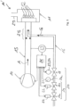
- FIG. 1 shows a schematic view of a first exemplary gas burner appliance 10.
- the gas burner appliance 10 comprises a combustion chamber 11 in which combustion of a gas/air mixture M having a defined mixing ratio of gas G and air A takes place during a regular combustion mode of the gas burner appliance 10, namely after a start-up of the gas burner appliance 10 and after successfully igniting the gas/air mixture M.
- the combustion of the gas/air mixture M results into flames 12 and into exhaust gas E.
- the flames 12 are monitored by a combustion quality sensor, preferably by a flame ionization sensor 13 providing as output signal an electrical flame ionization current.
- the flame ionization sensor 13 provides its output signal to a controller 26.
- the exhaust gas E emanates from the combustion chamber 11 through an exhaust pipe 29.
- the gas/air mixture M is provided to the combustion chamber 11 of the gas burner appliance 10 by mixing a flow of the air A with a flow of the gas G.
- a fan 14 sucks in air A flowing through an air duct 15 and gas G flowing through a gas duct 16.
- a gas flow modulator 18 for adjusting the gas flow through the gas duct 16 and a gas safety valve unit 19 having preferably two gas safety valves 19a, 19b are assigned to the gas duct 16.
- the gas flow modulator 18 and the gas safety valves 19a, 19b are part of a gas armature 17 further comprising a sieve 20 and an electrical or electronic absolute pressure sensor 21.
- the sieve 20 and the electrical or electronic absolute pressure sensor 21 are both assigned to the gas duct 16.
- the absolute pressure sensor 21 provides its output signal to the controller 26.
- the electrical or electronic absolute pressure sensor 21, namely the measuring point 21a of the same is positioned downstream of gas safety valve unit 19, namely downstream of the second gas safety valve 19b.
- the electrical or electronic absolute pressure sensor 21, namely the measuring point 21a of the same is positioned downstream of gas safety valve unit 19 und upstream of the gas flow modulator 18.
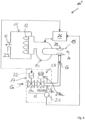
- the gas armature 17 of Figure 1 can be replaced by the gas armature 17 of Figure 2 .
- the electrical or electronic absolute pressure sensor 21, namely the measuring point 21a of the same is positioned downstream of the first gas safety valve 19a of the gas safety valve unit 19 and upstream or the second gas safety valve 19b of the gas safety valve unit 19.
- the gas safety valves 19a, 19b of the gas safety valve unit 19 are operated by electric coils 22 being part of the gas armature 17. In a regular combustion mode the electric coils 22 are energized by the controller 26 to open the gas safety valves 19a, 19b. In burner-off phases the gas safety valves 19 are closed.
- each gas safety valve 19a, 19b is operated by one separate electric coil 22. With the use of separate electric coils 22 is possible to open and close the gas safety valves 19a, 19b independently from each other. Alternatively, the gas safety valves 19a, 19b may be operated commonly by a common electric coil 22.
- the gas flow modulator 18 is operated by an actuator 23 also having at least one electric coil 24.
- the gas flow modulator 18 is an electric gas flow modulator 18 operated by the controller 26.
- the gas/air mixture M having the defined mixing ratio of gas G and air A is provided to the combustion chamber 11 of the gas burner appliance 10.
- the gas/air mixture M is provided by mixing the air flow A provided by an air duct 15 with a gas flow G provided by a gas duct 16.
- the air flow and the gas flow become preferably mixed by a mixing device 25.
- the mixing device 25 may be a venturi nozzle.
- the quantity of the air flow A and thereby the quantity of the gas/air mixture flow M is adjusted by the fan 14, namely by the speed of the fan 14.
- the fan speed can be adjusted on basis of a nominal burner-load.
- a nominal fan speed of the fan 14 depends on the nominal burner load.
- the fan 14 is operated by the controller 26.
- the fan speed range of the fan 14 defines a modulation range of the gas burner appliance 10.
- a modulation of "1" means that the fan 14 is operated at maximum fan speed (100% of maximum fan speed) and thereby at a full-load of the gas burner appliance 10.
- a modulation of "2” means that the fan 14 is operated at 50% of the maximum fan speed and a modulation of "5" means that the fan 14 is operated at 20% of the maximum fan speed.
- the defined mixing ratio of gas G and air A within the gas/air mixture M and thereby the ⁇ -value of the gas/air mixture M is kept at a defined value, preferably constant, over the entire modulation range of the gas burner appliance 10.
- Said defined mixing ratio of gas G and air A or said ⁇ -value of the gas/air mixture M is controlled over the modulation range of the gas burner appliance using the electric gas flow modulator 18 of a gas armature 17 to keep the defined mixing ratio of gas and air and thereby the ⁇ -value preferably constant over the modulation range of the gas burner appliance.
- the control variable for the electric gas flow modulator 18 in order to keep the ⁇ -value constant is generated by the controller 26 on basis of the flame ionization current provided by the flame ionization sensor 13.
- Figures 3 and 4 show schematic views of other exemplary gas burner appliances 10' and 10".
- Figures 1 , 2 , 3 and 4 identical reference numbers are used for identical parts. In order to avoid unnecessary repetitions, below only the differences of the gas burner appliances 10, 10' and 10, 10" will be described.
- the constant mixing ratio of gas G and air A within the gas/air mixture M is controlled by the electric gas flow modulator 18 on basis of a signal provided by an electric or electronic pressure sensor or flow meter 27 and not on basis of the flame ionization current provided by the flame ionization sensor 13.
- the electric or electronic sensor 27 may provide to the controller 26 an actual value corresponding to a pressure ratio between a gas pressure in a gas duct 16 and an air pressure in an air duct 15 or corresponding to a pressure ratio between the gas pressure in the gas duct 16 and the air pressure at the reference point, wherein the controller 26 may compare said actual value with a nominal value.
- the controller 26 may generate the control variable for the electric gas flow modulator 18 on basis of the control deviation between the actual value and the nominal value, wherein the gas flow modulator 18 may be operated on basis of this control variable to keep over the entire modulation range of the gas burner appliance 10 the defined mixing ratio of gas and air and thereby the ⁇ -value constant.
- the absolute pressure sensor 21 is positioned between the gas safety valve unit 19 and the gas flow modulator 18.
- the absolute pressure sensor 21, namely the measuring point 21a of the same may be positioned downstream of the first gas safety valve 19a and upstream of the second gas safety valve 19b.
- the gas armature 17 comprises a pneumatic gas flow regulator 28.
- a pneumatic controller 28a of the pneumatic gas flow regulator 28 controls the opening/closing position of the gas regulation valve 28b.
- the position of the pneumatic gas regulation valve 28b is adjusted by the pneumatic controller 28a on basis of a pressure difference between the gas pressure of the gas flow in the gas duct 16 and a reference pressure.
- the pneumatic gas regulation valve 28a is controlled by the pneumatic controller 28b in such a way that at the outlet pressure of the gas regulation valve 28b is equal to the reference pressure.
- the ambient pressure serves as reference pressure. However, it is also possible to use the air pressure of the air flow in the air duct 15 as reference pressure.
- the pressure difference between the gas pressure and the reference pressure is determined pneumatically a by pneumatic sensor of the pneumatic controller 28a.
- the mixing ratio of the defined gas/air mixture is controlled by the pneumatic controller 28a in such a way that over the entire modulation range of the gas burner appliance 10 the defined mixing ratio of the gas/air mixture M and thereby the ⁇ -value constant is kept constant.
- the absolute pressure sensor 21, namely the measuring point 21a of the same, is positioned between the pneumatic gas flow regulator 28 and the mixing device 25.
- the gas regulation valve 28b is in its closed position gas tight and acts also as second gas safety valve 19b. If the gas regulation valve 28b is in its closed position not gas tight, there would be separate second gas safety valve 19b and the absolute pressure sensor 21 may then alternatively be positioned between the first gas safety valve unit 19 and the pneumatic gas flow regulator 28 or between the two gas safety valves 19a, 19b.
- the gas burner appliances 10, 10', 10" need to execute a burner-start-up in which a provided gas/air mixture M having a defined mixing ratio of gas G and air A is successfully ignited. Only after successfully executing such a burner-start-up and thereby successfully igniting the gas/air mixture M, the gas burner appliance 10, 10', 10" can be operated in a regular combustion mode.
- Such a burner-start-up has at least an ignition phase and may in addition have a ventilation phase before the ignition phase.
- the ignition phase may also be called safety phase.
- the gas safety valves 19a, 19b are both closed and the fan 14 is running.
- the gas safety valves 19a, 19b are both opened and the fan 14 is running.
- an ignition device (not shown) is operated to ignite the gas/air mixture M.
- the output signal provided by the combustion quality sensor, in Figures 1 and 2 the output signal by the flame ionization sensor 13, may be used to detect if a burner-start-up was successful and resulted into an ignition of the gas/air mixture M.
- the gas burner appliances 10, 10', 10" go into lockout state if a defined number of burner-start-ups failed, namely did not result into a combustion. It is possible that a burner-start-up fails because a gas inlet pressure of the gas burner appliance 10, 10', 10" is too low. If the gas inlet pressure is too low, the gas content within the gas/air mixture M is too low to provide an ignitable gas/air mixture M. However, the gas burner appliance 10, 10', 10" should not go into a lockout state if a burner-start-up failed because of a gas inlet pressure being too low.
- the present invention relates to a method for operating such a gas burner appliance 10, 10', 10", to provide an electrical or electronic pressure-switch functionality thereby securing that the gas burner appliance 10, 10', 10" does not go into a lockout state if a burner-start-up failed because of a gas inlet pressure being too low.
- At least the following steps are executed: Before each burner-start-up of the gas burner appliance 10, 10', 10", measuring a first absolute pressure by the absolute pressure sensor 21 assigned to the gas duct 16 when the first gas safety valve 19a is closed, said first absolute pressure being representative of an ambient pressure.
- the absolute pressure sensor 21 is positioned downstream of the first gas safety valve 19a and upstream of the second gas safety valve 19 (see Figure 2 ), then the first absolute pressure is measured when the first gas safety valve 19b is closed, when the second gas safety valve 19a is opened, when the gas flow modulator 18 being in its closed position not gas tight is opened or closed, and when the fan 14 is not running.
- the gas regulation valve 28b is opened for the measurement of the first absolute pressure.
- the first absolute pressure is measured when the first gas safety valve 19a is closed, when second gas safety valve 19b is opened or closed, when the gas flow modulator 18 ( Figures 1 , 3 ) being in its closed position not gas tight is opened or closed, and when the fan 14 is not running.
- the gas regulation valve 28b is opened for the measurement of the first absolute pressure.
- the following step is executed: Measuring a second absolute pressure by the absolute pressure sensor 21, said second absolute pressure being representative of a gas pressure.
- the second absolute pressure is measured when the first gas safety valve 19a and the second gas safety valve 19b are both opened and when the fan 14 is running. Further, the gas flow modulator 18 or the gas regulation valve 28b is opened during a burner-start-up to provide a gas/air mixture M to the combustion chamber 11.
- a lockout of gas burner appliance 10, 10', 10" is allowed or prevented on basis of the comparison of the pressure difference with the threshold.
- the second pressure is measured continuously or at a defined sampling rate. Further, during each burner-start-up the pressure difference between the first absolute pressure and the second absolute pressure is determined continuously or at the defined sampling rate. Still further, during each burner-start-up the pressure difference is compared with the threshold continuously or at the defined sampling rate.
- the burner-start-up is terminated if during the respective burner-start-up the pressure difference is below the threshold.
- the terminated burner-start-up is not considered as a failed burner-start-up.
- each burner-start-up of the gas burner appliance 10, 10', 10" it is monitored if the burner-start-up results into a combustion of the gas/air mixture within a defined start-up time interval. If the burner-start-up did not result into a combustion within the defined start-up time interval and if the pressure difference determined during the start-up time interval is below the threshold, then not considering the burner-start-up is as a failed burner-start-up. If the burner-start-up did not result into a combustion within a defined start-up time interval and if the pressure difference determined during the start-up time interval is above the threshold, then considering the burner-start-up as a failed burner-start-up.
- first gas safety valve 19a and a second gas safety valve 19b can be opened and closed independently from each other, then the following streps may be executed: Measuring also before the burner-start-up of the gas burner appliance 10 the second absolute pressure by the absolute pressure sensor 21 when the first gas safety valve 19a is opened and the second gas safety valve 19b is closed. For this measurement the fan 14 is not running. Further, determining the pressure difference between the first absolute pressure and the second absolute pressure. Still further, comparing the pressure difference with the threshold. The burner-start-up is prevented when the pressure difference is below the threshold. The burner-start-up is allowed when the pressure difference is above the threshold. This is of advantage to avoid that a gas/air mixture which is not ignitable enters into the combustion chamber 11 in connection with a burner-start-up.
- the method may comprise the following additional steps: If a burner-start-up has not been considered as a failed burner-start-up, then preventing a new burner-start-up of the gas burner appliance 10 for a defined recheck time interval. Executing again the above steps providing the electrical or electronic pressure-switch functionality after the defined recheck time interval is expired. So, if a burner-start-up did not result into an ignition but has not been considered as a failed burner-start-up, then a new burner-start-up is executed for security reasons only after the defined recheck time interval.
- the start-up time interval is also called safety time interval.
- This start-up time interval is the maximum time interval for the burner-start-up in which the safety gas valves 19a, 19b are opened without detection of a flame 12.
- a burner-start-up may be terminated before the end of the defined start-up time interval if it is detected during this start-up time interval that the pressure difference is below the threshold, meaning that the gas inlet pressure is insufficient. Such a terminated burner-start-up will also not be considered as a failed burner-start-up.
- the method may comprise the following additional steps: If the burner-start-up results into a combustion within the defined start-up time interval, then measuring during a regular combustion mode the second pressure continuously or at a defined sampling rate. Determining during the regular combustion mode the pressure difference between the first absolute pressure and the second absolute pressure continuously or at the defined sampling rate during combustion. Comparing during the regular combustion mode the pressure difference with the threshold continuously or at the defined sampling rate. If during regular combustion the pressure difference drops below the threshold during combustion, then terminating the combustion. This increases security during a regular combustion mode.
- the invention also relates to a gas burner appliance 10, 10', 10" having the controller 26 for operating the gas burner appliance 10, 10', 10", wherein the controller 26 is configured to execute the above-described method.
- the controller 26 is configured provide an electrical or electronic pressure-switch functionality by executing the following steps: Before each burner-start-up of the gas burner appliance 10, 10', 10", measure a first absolute pressure by the absolute pressure sensor 21 when the first gas safety valve 19a is closed, said first absolute pressure being representative of an ambient pressure.
- Allow or prevent a lockout of gas burner appliance 10, 10', 10" is on basis of the comparison of the pressure difference with the threshold.
Landscapes
- Engineering & Computer Science (AREA)
- Chemical & Material Sciences (AREA)
- Combustion & Propulsion (AREA)
- Mechanical Engineering (AREA)
- General Engineering & Computer Science (AREA)
- Regulation And Control Of Combustion (AREA)
Claims (7)
- Procédé pour faire fonctionner un appareil à brûleur à gaz (10, 10', 10"), l'appareil à brûleur à gaz comprenant :une chambre de combustion (11) configurée pour brûler un mélange gaz/air défini,un dispositif de mélange (23) configuré pour fournir ledit mélange gaz/air en mélangeant un flux d'air fourni par un conduit d'air (15) avec un flux de gaz fourni par un conduit de gaz (16),un ventilateur (14) configuré pour fournir le flux d'air ou le flux du mélange gaz/air,une unité de soupape de sécurité de gaz (19) associée au conduit de gaz (16) et configurée pour ouvrir ou fermer le conduit de gaz (16),
l'unité de soupape de sécurité de gaz (19) comportant une première soupape de sécurité de gaz (19a) et une seconde soupape de sécurité de gaz (19b) positionnée en aval de la première soupape de sécurité de gaz (19a),un modulateur d'écoulement de gaz (18) ou un régulateur d'écoulement de gaz (28) associé au conduit de gaz (16) étant configuré pour maintenir le rapport de mélange du gaz et de l'air à une valeur définie,un capteur de pression absolue électrique ou électronique (21) associé au conduit de gaz (16) et positionné en aval de la première soupape de sécurité de gaz (19a),dans lequel l'appareil à brûleur à gaz (10) passe en état de verrouillage si un nombre défini de démarrages du brûleur de l'appareil à brûleur à gaz a échoué, à savoir n'a pas abouti à une combustion,dans lequel l'appareil à brûleur à gaz (10, 10', 10") est actionné par l'exécution des étapes suivantes pour fournir une fonctionnalité de commutation de pression électrique ou électronique :avant chaque démarrage du brûleur de l'appareil à brûleur à gaz, mesurer une première pression absolue par le capteur de pression absolue (21) lorsque la première soupape de sécurité de gaz (19a) est fermée, ladite première pression absolue étant représentative d'une pression ambiante, dans lequelsi le capteur de pression absolue électrique ou électronique (21) est positionné en aval de la première soupape de sécurité de gaz (19a) et en amont de la seconde soupape de sécurité de gaz (19b), mesurer la première pression absolue lorsque la première soupape de sécurité de gaz (19a) est fermée, lorsque la seconde soupape de sécurité de gaz (19b) est ouverte et lorsque le ventilateur (14) ne fonctionne pas, ousi le capteur de pression absolue électrique ou électronique (21) est positionné en aval de la seconde soupape de sécurité de gaz (19b), mesurer la première pression absolue lorsque la première soupape de sécurité de gaz (19a) est fermée, lorsque la seconde soupape de sécurité de gaz (19b) est ouverte ou fermée, et lorsque le ventilateur (14) ne fonctionne pas,pendant chaque démarrage du brûleur de l'appareil à brûleur à gaz :mesurer une seconde pression absolue par le capteur de pression absolue (21) lorsque la première soupape de sécurité de gaz (19a) est ouverte, cette seconde pression absolue étant représentative d'une pression de gaz, dans lequelsi le capteur de pression absolue électrique ou électronique (21) est positionné en aval de la première soupape de sécurité de gaz (19a) et en amont de la seconde soupape de sécurité de gaz (19b), mesurer la seconde pression absolue pendant le démarrage du brûleur, lorsque la première soupape de sécurité de gaz (19a) et la seconde soupape de sécurité de gaz (19b) sont toutes deux ouvertes et que le ventilateur (14) fonctionne,si le capteur de pression absolue électrique ou électronique (21) est positionné en aval de la seconde soupape de sécurité de gaz (19b), mesurer la seconde pression absolue pendant le démarrage du brûleur, lorsque la première soupape de sécurité de gaz (19a) et la seconde soupape de sécurité de gaz (19b) sont toutes deux ouvertes et que le ventilateur fonctionne,déterminer une différence de pression entre la première pression absolue et la seconde pression absolue,comparer la différence de pression à un seuil,dans lequel un verrouillage de l'appareil à brûleur à gaz est autorisé ou empêché sur la base de la comparaison de la différence de pression avec le seuil. - Procédé selon la revendication 1, dans lequelpendant chaque démarrage du brûleur de l'appareil à brûleur à gazla seconde pression est mesurée en continu ou à une fréquence d'échantillonnage définie,la différence de pression entre la première pression absolue et la seconde pression absolue est déterminée en continu ou à la fréquence d'échantillonnage définie,la différence de pression est comparée au seuil en continu ou à la fréquence d'échantillonnage définie,le démarrage du brûleur est interrompu si, au cours de ce démarrage, la différence de pression est inférieure au seuil,un tel démarrage de brûleur terminé n'est pas considéré comme un démarrage de brûleur échoué.
- Procédé selon la revendication 1 ou 2, dans lequel
pendant chaque démarrage du brûleur de l'appareil à brûleur à gaz, on vérifie si le démarrage du brûleur aboutit à une combustion du mélange gaz/air dans un intervalle de temps de démarrage défini, dans lequelsi le démarrage du brûleur n'a pas abouti à une combustion dans l'intervalle de temps de démarrage défini et si la différence de pression déterminée pendant l'intervalle de temps de démarrage est inférieure au seuil, le démarrage du brûleur n'est pas considéré comme un démarrage de brûleur échoué,si le démarrage du brûleur n'a pas abouti à une combustion dans l'intervalle de temps de démarrage défini et si la différence de pression déterminée pendant l'intervalle de temps de démarrage est supérieure au seuil, le démarrage du brûleur est considéré comme un démarrage de brûleur échoué, - Procédé selon l'une des revendications 1 à 3, dans lequel
si la première soupape de sécurité de gaz (19a) et la seconde soupape de sécurité de gaz (19b) peuvent être ouvertes et fermées indépendamment l'une de l'autre, alorsmesurer également, avant le démarrage du brûleur de l'appareil à brûleur à gaz, la seconde pression absolue par le capteur de pression absolue (21) lorsque la première soupape de sécurité de gaz (19a) est ouverte, lorsque la seconde soupape de sécurité de gaz (19b) est fermée et lorsque le ventilateur (14) ne fonctionne pas,déterminer la différence de pression entre la première pression absolue et la seconde pression absolue,comparer la différence de pression avec le seuil,dans lequel le démarrage du brûleur est empêché lorsque la différence de pression est inférieure au seuil,dans lequel le démarrage du brûleur est autorisé lorsque la différence de pression est supérieure au seuil. - Procédé selon l'une des revendications 1 à 4, dans lequelsi un démarrage du brûleur n'a pas été considéré comme un démarrage de brûleur échoué, empêcher un nouveau démarrage du brûleur à gaz pendant un intervalle de temps de revérification défini,exécuter à nouveau les étapes selon l'une des revendications 1 à 4 en assurant la fonctionnalité de commutation de pression électrique ou électronique après l'expiration de l'intervalle de temps de revérification défini.
- Procédé selon l'une des revendications 1 à 5, dans lequel
si le démarrage du brûleur aboutit à une combustion, alorsmesurer, pendant un mode de combustion normal, la seconde pression en continu ou à une fréquence d'échantillonnage définie,déterminer, pendant le mode de combustion normal, la différence de pression entre la première pression absolue et la seconde pression absolue en continu ou à la fréquence d'échantillonnage définie pendant la combustion, etcomparer, pendant le mode de combustion normal, la différence de pression avec le seuil en continu ou à la fréquence d'échantillonnage définie,si, au cours de la combustion, la différence de pression tombe en dessous du seuil, la combustion est interrompue. - Appareil à brûleur à gaz (10, 10', 10") comprenant un dispositif de commande (26) pour faire fonctionner l'appareil à brûleur à gaz (10, 10', 10"),le dispositif de commande (26) est configuré pour fournir une fonctionnalité de commutation de pression électrique ou électronique en exécutant les étapes suivantes :
avant chaque démarrage du brûleur de l'appareil à brûleur à gaz (10, 10', 10"), mesurer une première pression absolue par un capteur de pression absolue (21) associé à un conduit de gaz lorsqu'une première soupape de sécurité de gaz (19a) associée au conduit de gaz est fermée, une seconde soupape de sécurité de gaz (19b) étant positionnée en aval de la première soupape de sécurité de gaz (19a), ladite première pression absolue étant représentative d'une pression ambiante, dans lequelsi le capteur de pression absolue électrique ou électronique (21) est positionné en aval de la première soupape de sécurité de gaz (19a) et en amont de la seconde soupape de sécurité de gaz (19b), mesurer la première pression absolue lorsque la première soupape de sécurité de gaz (19a) est fermée, lorsque la seconde soupape de sécurité de gaz (19b) est ouverte et lorsque le ventilateur (14) ne fonctionne pas, ousi le capteur de pression absolue électrique ou électronique (21) est positionné en aval de la seconde soupape de sécurité de gaz (19b), mesurer la première pression absolue lorsque la première soupape de sécurité de gaz (19a) est fermée, lorsque la seconde soupape de sécurité de gaz (19b) est ouverte ou fermée, et lorsque le ventilateur (14) ne fonctionne pas,pendant chaque démarrage du brûleur de l'appareil à brûleur à gaz (10, 10', 10") :mesurer une seconde pression absolue par le capteur de pression absolue (21) lorsqu'au moins la première soupape de sécurité de gaz (19a) est ouverte, cette seconde pression absolue étant représentative d'une pression de gaz, dans lequelsi le capteur de pression absolue électrique ou électronique (21) est positionné en aval de la première soupape de sécurité de gaz (19a) et en amont de la seconde soupape de sécurité de gaz (19b), mesurer la seconde pression absolue pendant le démarrage du brûleur, lorsque la première soupape de sécurité de gaz (19a) et la seconde soupape de sécurité de gaz (19b) sont toutes deux ouvertes et que le ventilateur (14) fonctionne,si le capteur de pression absolue électrique ou électronique (21) est positionné en aval de la seconde soupape de sécurité de gaz (19b), mesurer la seconde pression absolue pendant le démarrage du brûleur, lorsque la première soupape de sécurité de gaz (19a) et la seconde soupape de sécurité de gaz (19b) sont toutes deux ouvertes et que le ventilateur fonctionne,déterminer une différence de pression entre la première pression absolue et la seconde pression absolue,comparer la différence de pression à un seuil,autoriser ou empêcher le verrouillage de l'appareil à brûleur à gaz (10, 10', 10") sur la base de la comparaison de la différence de pression avec le seuil.
Priority Applications (4)
| Application Number | Priority Date | Filing Date | Title |
|---|---|---|---|
| EP21185472.4A EP4119845B1 (fr) | 2021-07-14 | 2021-07-14 | Procédé et appareil de commande pour faire fonctionner un appareil à brûleur à gaz |
| CN202280061968.8A CN117940705A (zh) | 2021-07-14 | 2022-07-11 | 用于操作燃气燃烧器设备的方法和控制器 |
| PCT/EP2022/069242 WO2023285345A1 (fr) | 2021-07-14 | 2022-07-11 | Procédé et dispositif de commande d'actionnement d'appareil à brûleur à gaz |
| US18/579,207 US20240328621A1 (en) | 2021-07-14 | 2022-07-11 | Method and Controller for Operating a Gas Burner Appliance |
Applications Claiming Priority (1)
| Application Number | Priority Date | Filing Date | Title |
|---|---|---|---|
| EP21185472.4A EP4119845B1 (fr) | 2021-07-14 | 2021-07-14 | Procédé et appareil de commande pour faire fonctionner un appareil à brûleur à gaz |
Publications (2)
| Publication Number | Publication Date |
|---|---|
| EP4119845A1 EP4119845A1 (fr) | 2023-01-18 |
| EP4119845B1 true EP4119845B1 (fr) | 2024-10-16 |
Family
ID=77042704
Family Applications (1)
| Application Number | Title | Priority Date | Filing Date |
|---|---|---|---|
| EP21185472.4A Active EP4119845B1 (fr) | 2021-07-14 | 2021-07-14 | Procédé et appareil de commande pour faire fonctionner un appareil à brûleur à gaz |
Country Status (4)
| Country | Link |
|---|---|
| US (1) | US20240328621A1 (fr) |
| EP (1) | EP4119845B1 (fr) |
| CN (1) | CN117940705A (fr) |
| WO (1) | WO2023285345A1 (fr) |
Families Citing this family (1)
| Publication number | Priority date | Publication date | Assignee | Title |
|---|---|---|---|---|
| EP4033148B1 (fr) * | 2021-01-25 | 2023-11-01 | Pittway Sarl | Procédé et appareil de commande pour faire fonctionner un appareil à brûleur à gaz |
Family Cites Families (8)
| Publication number | Priority date | Publication date | Assignee | Title |
|---|---|---|---|---|
| GB9716151D0 (en) | 1997-08-01 | 1997-10-08 | Heanley Christopher R | Boiler systems |
| DE19824521B4 (de) | 1998-06-02 | 2004-12-23 | Honeywell B.V. | Regeleinrichtung für Gasbrenner |
| FR2818746B1 (fr) * | 2000-12-26 | 2003-03-28 | Gaz De France | Procede et dispositif d'evaluation de l'indice de wobbe d'un gaz combustible |
| US9846440B2 (en) * | 2011-12-15 | 2017-12-19 | Honeywell International Inc. | Valve controller configured to estimate fuel comsumption |
| US9074770B2 (en) | 2011-12-15 | 2015-07-07 | Honeywell International Inc. | Gas valve with electronic valve proving system |
| EP2667097B1 (fr) | 2012-05-24 | 2018-03-07 | Honeywell Technologies Sarl | Procédé de fonctionnement d'un brûleur à gaz |
| US9645584B2 (en) | 2014-09-17 | 2017-05-09 | Honeywell International Inc. | Gas valve with electronic health monitoring |
| JP2017116382A (ja) * | 2015-12-24 | 2017-06-29 | 三浦工業株式会社 | ガス漏れ検出装置及びガス漏れ検出方法 |
-
2021
- 2021-07-14 EP EP21185472.4A patent/EP4119845B1/fr active Active
-
2022
- 2022-07-11 US US18/579,207 patent/US20240328621A1/en active Pending
- 2022-07-11 WO PCT/EP2022/069242 patent/WO2023285345A1/fr not_active Ceased
- 2022-07-11 CN CN202280061968.8A patent/CN117940705A/zh active Pending
Also Published As
| Publication number | Publication date |
|---|---|
| EP4119845A1 (fr) | 2023-01-18 |
| WO2023285345A1 (fr) | 2023-01-19 |
| US20240328621A1 (en) | 2024-10-03 |
| CN117940705A (zh) | 2024-04-26 |
Similar Documents
| Publication | Publication Date | Title |
|---|---|---|
| EP3228936B1 (fr) | Procédé de fonctionnement d'un appareil à brûleur à gaz | |
| US7241135B2 (en) | Feedback control for modulating gas burner | |
| EP2685169B1 (fr) | Procédé de fonctionnement d'un brûleur à gaz | |
| EP4119845B1 (fr) | Procédé et appareil de commande pour faire fonctionner un appareil à brûleur à gaz | |
| US11635206B2 (en) | Method and controller for operating a gas burner appliance | |
| EP3043115B1 (fr) | Procédé pour faire fonctionner un brûleur à gaz à prémélange | |
| EP2631541B1 (fr) | Procédé de fonctionnement d'un brûleur à gaz | |
| EP4092325B1 (fr) | Procédé et appareil de commande pour faire fonctionner un appareil à brûleur à gaz | |
| EP4119846B1 (fr) | Procédé et appareil de commande pour faire fonctionner un appareil à brûleur à gaz | |
| EP4155609B1 (fr) | Procédé et appareil de commande pour faire fonctionner un appareil à brûleur à gaz | |
| EP4033148B1 (fr) | Procédé et appareil de commande pour faire fonctionner un appareil à brûleur à gaz | |
| US20230090905A1 (en) | Flame monitoring device for a gas burner appliance and gas burner appliance | |
| US11287131B2 (en) | Method for operating a gas burner appliance | |
| JP2001235141A (ja) | 燃焼装置 | |
| WO2024228280A1 (fr) | Dispositif de combustion | |
| JP2024002212A (ja) | 燃焼装置 | |
| JPH01174820A (ja) | ガス燃焼機器の空燃比調整装置 | |
| JPH08320117A (ja) | ガス燃焼器 | |
| JPH0440609B2 (fr) | ||
| JP2001235140A (ja) | 全一次式燃焼バーナの燃焼制御装置 |
Legal Events
| Date | Code | Title | Description |
|---|---|---|---|
| PUAI | Public reference made under article 153(3) epc to a published international application that has entered the european phase |
Free format text: ORIGINAL CODE: 0009012 |
|
| STAA | Information on the status of an ep patent application or granted ep patent |
Free format text: STATUS: THE APPLICATION HAS BEEN PUBLISHED |
|
| AK | Designated contracting states |
Kind code of ref document: A1 Designated state(s): AL AT BE BG CH CY CZ DE DK EE ES FI FR GB GR HR HU IE IS IT LI LT LU LV MC MK MT NL NO PL PT RO RS SE SI SK SM TR |
|
| STAA | Information on the status of an ep patent application or granted ep patent |
Free format text: STATUS: REQUEST FOR EXAMINATION WAS MADE |
|
| 17P | Request for examination filed |
Effective date: 20230717 |
|
| RBV | Designated contracting states (corrected) |
Designated state(s): AL AT BE BG CH CY CZ DE DK EE ES FI FR GB GR HR HU IE IS IT LI LT LU LV MC MK MT NL NO PL PT RO RS SE SI SK SM TR |
|
| P01 | Opt-out of the competence of the unified patent court (upc) registered |
Effective date: 20230827 |
|
| RIC1 | Information provided on ipc code assigned before grant |
Ipc: F23N 5/18 20060101ALN20240322BHEP Ipc: F23N 5/24 20060101ALI20240322BHEP Ipc: F23N 5/12 20060101ALI20240322BHEP Ipc: F23N 1/02 20060101AFI20240322BHEP |
|
| GRAP | Despatch of communication of intention to grant a patent |
Free format text: ORIGINAL CODE: EPIDOSNIGR1 |
|
| STAA | Information on the status of an ep patent application or granted ep patent |
Free format text: STATUS: GRANT OF PATENT IS INTENDED |
|
| RIC1 | Information provided on ipc code assigned before grant |
Ipc: F23N 5/18 20060101ALN20240402BHEP Ipc: F23N 5/24 20060101ALI20240402BHEP Ipc: F23N 5/12 20060101ALI20240402BHEP Ipc: F23N 1/02 20060101AFI20240402BHEP |
|
| INTG | Intention to grant announced |
Effective date: 20240506 |
|
| RIC1 | Information provided on ipc code assigned before grant |
Ipc: F23N 5/18 20060101ALN20240419BHEP Ipc: F23N 5/24 20060101ALI20240419BHEP Ipc: F23N 5/12 20060101ALI20240419BHEP Ipc: F23N 1/02 20060101AFI20240419BHEP |
|
| GRAS | Grant fee paid |
Free format text: ORIGINAL CODE: EPIDOSNIGR3 |
|
| GRAA | (expected) grant |
Free format text: ORIGINAL CODE: 0009210 |
|
| STAA | Information on the status of an ep patent application or granted ep patent |
Free format text: STATUS: THE PATENT HAS BEEN GRANTED |
|
| AK | Designated contracting states |
Kind code of ref document: B1 Designated state(s): AL AT BE BG CH CY CZ DE DK EE ES FI FR GB GR HR HU IE IS IT LI LT LU LV MC MK MT NL NO PL PT RO RS SE SI SK SM TR |
|
| REG | Reference to a national code |
Ref country code: GB Ref legal event code: FG4D |
|
| REG | Reference to a national code |
Ref country code: CH Ref legal event code: EP Ref country code: DE Ref legal event code: R096 Ref document number: 602021020250 Country of ref document: DE |
|
| REG | Reference to a national code |
Ref country code: IE Ref legal event code: FG4D |
|
| REG | Reference to a national code |
Ref country code: NL Ref legal event code: FP |
|
| REG | Reference to a national code |
Ref country code: LT Ref legal event code: MG9D |
|
| REG | Reference to a national code |
Ref country code: AT Ref legal event code: MK05 Ref document number: 1733177 Country of ref document: AT Kind code of ref document: T Effective date: 20241016 |
|
| PG25 | Lapsed in a contracting state [announced via postgrant information from national office to epo] |
Ref country code: IS Free format text: LAPSE BECAUSE OF FAILURE TO SUBMIT A TRANSLATION OF THE DESCRIPTION OR TO PAY THE FEE WITHIN THE PRESCRIBED TIME-LIMIT Effective date: 20250216 Ref country code: PT Free format text: LAPSE BECAUSE OF FAILURE TO SUBMIT A TRANSLATION OF THE DESCRIPTION OR TO PAY THE FEE WITHIN THE PRESCRIBED TIME-LIMIT Effective date: 20250217 Ref country code: HR Free format text: LAPSE BECAUSE OF FAILURE TO SUBMIT A TRANSLATION OF THE DESCRIPTION OR TO PAY THE FEE WITHIN THE PRESCRIBED TIME-LIMIT Effective date: 20241016 |
|
| PG25 | Lapsed in a contracting state [announced via postgrant information from national office to epo] |
Ref country code: FI Free format text: LAPSE BECAUSE OF FAILURE TO SUBMIT A TRANSLATION OF THE DESCRIPTION OR TO PAY THE FEE WITHIN THE PRESCRIBED TIME-LIMIT Effective date: 20241016 |
|
| PG25 | Lapsed in a contracting state [announced via postgrant information from national office to epo] |
Ref country code: BG Free format text: LAPSE BECAUSE OF FAILURE TO SUBMIT A TRANSLATION OF THE DESCRIPTION OR TO PAY THE FEE WITHIN THE PRESCRIBED TIME-LIMIT Effective date: 20241016 |
|
| PG25 | Lapsed in a contracting state [announced via postgrant information from national office to epo] |
Ref country code: ES Free format text: LAPSE BECAUSE OF FAILURE TO SUBMIT A TRANSLATION OF THE DESCRIPTION OR TO PAY THE FEE WITHIN THE PRESCRIBED TIME-LIMIT Effective date: 20241016 |
|
| PG25 | Lapsed in a contracting state [announced via postgrant information from national office to epo] |
Ref country code: NO Free format text: LAPSE BECAUSE OF FAILURE TO SUBMIT A TRANSLATION OF THE DESCRIPTION OR TO PAY THE FEE WITHIN THE PRESCRIBED TIME-LIMIT Effective date: 20250116 |
|
| PG25 | Lapsed in a contracting state [announced via postgrant information from national office to epo] |
Ref country code: GR Free format text: LAPSE BECAUSE OF FAILURE TO SUBMIT A TRANSLATION OF THE DESCRIPTION OR TO PAY THE FEE WITHIN THE PRESCRIBED TIME-LIMIT Effective date: 20250117 Ref country code: AT Free format text: LAPSE BECAUSE OF FAILURE TO SUBMIT A TRANSLATION OF THE DESCRIPTION OR TO PAY THE FEE WITHIN THE PRESCRIBED TIME-LIMIT Effective date: 20241016 Ref country code: LV Free format text: LAPSE BECAUSE OF FAILURE TO SUBMIT A TRANSLATION OF THE DESCRIPTION OR TO PAY THE FEE WITHIN THE PRESCRIBED TIME-LIMIT Effective date: 20241016 |
|
| PG25 | Lapsed in a contracting state [announced via postgrant information from national office to epo] |
Ref country code: PL Free format text: LAPSE BECAUSE OF FAILURE TO SUBMIT A TRANSLATION OF THE DESCRIPTION OR TO PAY THE FEE WITHIN THE PRESCRIBED TIME-LIMIT Effective date: 20241016 |
|
| PG25 | Lapsed in a contracting state [announced via postgrant information from national office to epo] |
Ref country code: RS Free format text: LAPSE BECAUSE OF FAILURE TO SUBMIT A TRANSLATION OF THE DESCRIPTION OR TO PAY THE FEE WITHIN THE PRESCRIBED TIME-LIMIT Effective date: 20250116 |
|
| PG25 | Lapsed in a contracting state [announced via postgrant information from national office to epo] |
Ref country code: SM Free format text: LAPSE BECAUSE OF FAILURE TO SUBMIT A TRANSLATION OF THE DESCRIPTION OR TO PAY THE FEE WITHIN THE PRESCRIBED TIME-LIMIT Effective date: 20241016 |
|
| PG25 | Lapsed in a contracting state [announced via postgrant information from national office to epo] |
Ref country code: DK Free format text: LAPSE BECAUSE OF FAILURE TO SUBMIT A TRANSLATION OF THE DESCRIPTION OR TO PAY THE FEE WITHIN THE PRESCRIBED TIME-LIMIT Effective date: 20241016 |
|
| REG | Reference to a national code |
Ref country code: DE Ref legal event code: R097 Ref document number: 602021020250 Country of ref document: DE |
|
| PG25 | Lapsed in a contracting state [announced via postgrant information from national office to epo] |
Ref country code: EE Free format text: LAPSE BECAUSE OF FAILURE TO SUBMIT A TRANSLATION OF THE DESCRIPTION OR TO PAY THE FEE WITHIN THE PRESCRIBED TIME-LIMIT Effective date: 20241016 |
|
| PG25 | Lapsed in a contracting state [announced via postgrant information from national office to epo] |
Ref country code: RO Free format text: LAPSE BECAUSE OF FAILURE TO SUBMIT A TRANSLATION OF THE DESCRIPTION OR TO PAY THE FEE WITHIN THE PRESCRIBED TIME-LIMIT Effective date: 20241016 |
|
| PG25 | Lapsed in a contracting state [announced via postgrant information from national office to epo] |
Ref country code: SK Free format text: LAPSE BECAUSE OF FAILURE TO SUBMIT A TRANSLATION OF THE DESCRIPTION OR TO PAY THE FEE WITHIN THE PRESCRIBED TIME-LIMIT Effective date: 20241016 |
|
| PG25 | Lapsed in a contracting state [announced via postgrant information from national office to epo] |
Ref country code: CZ Free format text: LAPSE BECAUSE OF FAILURE TO SUBMIT A TRANSLATION OF THE DESCRIPTION OR TO PAY THE FEE WITHIN THE PRESCRIBED TIME-LIMIT Effective date: 20241016 |
|
| PGFP | Annual fee paid to national office [announced via postgrant information from national office to epo] |
Ref country code: NL Payment date: 20250724 Year of fee payment: 5 |
|
| PLBE | No opposition filed within time limit |
Free format text: ORIGINAL CODE: 0009261 |
|
| STAA | Information on the status of an ep patent application or granted ep patent |
Free format text: STATUS: NO OPPOSITION FILED WITHIN TIME LIMIT |
|
| PG25 | Lapsed in a contracting state [announced via postgrant information from national office to epo] |
Ref country code: SE Free format text: LAPSE BECAUSE OF FAILURE TO SUBMIT A TRANSLATION OF THE DESCRIPTION OR TO PAY THE FEE WITHIN THE PRESCRIBED TIME-LIMIT Effective date: 20241016 |
|
| 26N | No opposition filed |
Effective date: 20250717 |
|
| PGFP | Annual fee paid to national office [announced via postgrant information from national office to epo] |
Ref country code: DE Payment date: 20250827 Year of fee payment: 5 |
|
| PGFP | Annual fee paid to national office [announced via postgrant information from national office to epo] |
Ref country code: TR Payment date: 20250702 Year of fee payment: 5 Ref country code: IT Payment date: 20250721 Year of fee payment: 5 |
|
| PGFP | Annual fee paid to national office [announced via postgrant information from national office to epo] |
Ref country code: GB Payment date: 20250722 Year of fee payment: 5 |
|
| PGFP | Annual fee paid to national office [announced via postgrant information from national office to epo] |
Ref country code: FR Payment date: 20250725 Year of fee payment: 5 |
|
| REG | Reference to a national code |
Ref country code: CH Ref legal event code: H13 Free format text: ST27 STATUS EVENT CODE: U-0-0-H10-H13 (AS PROVIDED BY THE NATIONAL OFFICE) Effective date: 20260224 |
|
| PG25 | Lapsed in a contracting state [announced via postgrant information from national office to epo] |
Ref country code: LU Free format text: LAPSE BECAUSE OF NON-PAYMENT OF DUE FEES Effective date: 20250714 |
|
| REG | Reference to a national code |
Ref country code: BE Ref legal event code: MM Effective date: 20250731 |
|
| PG25 | Lapsed in a contracting state [announced via postgrant information from national office to epo] |
Ref country code: BE Free format text: LAPSE BECAUSE OF NON-PAYMENT OF DUE FEES Effective date: 20250731 |