EP4119876A1 - Appareil frigorifique électroménager doté d'un récipient interne et d'un module de source lumineuse disposé sur celui-ci, comportant un bord spécifique de sortie de la lumière - Google Patents
Appareil frigorifique électroménager doté d'un récipient interne et d'un module de source lumineuse disposé sur celui-ci, comportant un bord spécifique de sortie de la lumière Download PDFInfo
- Publication number
- EP4119876A1 EP4119876A1 EP22181740.6A EP22181740A EP4119876A1 EP 4119876 A1 EP4119876 A1 EP 4119876A1 EP 22181740 A EP22181740 A EP 22181740A EP 4119876 A1 EP4119876 A1 EP 4119876A1
- Authority
- EP
- European Patent Office
- Prior art keywords
- cover
- light source
- housing
- refrigeration appliance
- source module
- Prior art date
- Legal status (The legal status is an assumption and is not a legal conclusion. Google has not performed a legal analysis and makes no representation as to the accuracy of the status listed.)
- Granted
Links
Images


Classifications
-
- F—MECHANICAL ENGINEERING; LIGHTING; HEATING; WEAPONS; BLASTING
- F25—REFRIGERATION OR COOLING; COMBINED HEATING AND REFRIGERATION SYSTEMS; HEAT PUMP SYSTEMS; MANUFACTURE OR STORAGE OF ICE; LIQUEFACTION SOLIDIFICATION OF GASES
- F25D—REFRIGERATORS; COLD ROOMS; ICE-BOXES; COOLING OR FREEZING APPARATUS NOT OTHERWISE PROVIDED FOR
- F25D11/00—Self-contained movable devices, e.g. domestic refrigerators
- F25D11/02—Self-contained movable devices, e.g. domestic refrigerators with cooling compartments at different temperatures
-
- F—MECHANICAL ENGINEERING; LIGHTING; HEATING; WEAPONS; BLASTING
- F25—REFRIGERATION OR COOLING; COMBINED HEATING AND REFRIGERATION SYSTEMS; HEAT PUMP SYSTEMS; MANUFACTURE OR STORAGE OF ICE; LIQUEFACTION SOLIDIFICATION OF GASES
- F25D—REFRIGERATORS; COLD ROOMS; ICE-BOXES; COOLING OR FREEZING APPARATUS NOT OTHERWISE PROVIDED FOR
- F25D27/00—Lighting arrangements
-
- F—MECHANICAL ENGINEERING; LIGHTING; HEATING; WEAPONS; BLASTING
- F21—LIGHTING
- F21V—FUNCTIONAL FEATURES OR DETAILS OF LIGHTING DEVICES OR SYSTEMS THEREOF; STRUCTURAL COMBINATIONS OF LIGHTING DEVICES WITH OTHER ARTICLES, NOT OTHERWISE PROVIDED FOR
- F21V33/00—Structural combinations of lighting devices with other articles, not otherwise provided for
- F21V33/0004—Personal or domestic articles
- F21V33/0044—Household appliances, e.g. washing machines or vacuum cleaners
-
- F—MECHANICAL ENGINEERING; LIGHTING; HEATING; WEAPONS; BLASTING
- F21—LIGHTING
- F21V—FUNCTIONAL FEATURES OR DETAILS OF LIGHTING DEVICES OR SYSTEMS THEREOF; STRUCTURAL COMBINATIONS OF LIGHTING DEVICES WITH OTHER ARTICLES, NOT OTHERWISE PROVIDED FOR
- F21V5/00—Refractors for light sources
- F21V5/02—Refractors for light sources of prismatic shape
-
- F—MECHANICAL ENGINEERING; LIGHTING; HEATING; WEAPONS; BLASTING
- F25—REFRIGERATION OR COOLING; COMBINED HEATING AND REFRIGERATION SYSTEMS; HEAT PUMP SYSTEMS; MANUFACTURE OR STORAGE OF ICE; LIQUEFACTION SOLIDIFICATION OF GASES
- F25D—REFRIGERATORS; COLD ROOMS; ICE-BOXES; COOLING OR FREEZING APPARATUS NOT OTHERWISE PROVIDED FOR
- F25D23/00—General constructional features
- F25D23/06—Walls
- F25D23/065—Details
-
- F—MECHANICAL ENGINEERING; LIGHTING; HEATING; WEAPONS; BLASTING
- F21—LIGHTING
- F21Y—INDEXING SCHEME ASSOCIATED WITH SUBCLASSES F21K, F21L, F21S and F21V, RELATING TO THE FORM OR THE KIND OF THE LIGHT SOURCES OR OF THE COLOUR OF THE LIGHT EMITTED
- F21Y2115/00—Light-generating elements of semiconductor light sources
- F21Y2115/10—Light-emitting diodes [LED]
Definitions
- One aspect of the invention relates to a household refrigeration appliance with an inner container which uses walls to delimit at least one storage space for food in the household refrigeration appliance.
- the household refrigeration appliance also has at least one light source module, which is arranged on a wall of the inner container and which emits light into the receiving space.
- the light source module has a transparent cover through which light of a light source of the light source module is emitted from the light source module.
- Such a household refrigerator is, for example, from EP 2 594 880 B1 known.
- the cover is designed as an angled element.
- An angular part of this cover which is oriented parallel to the wall of the inner container, is non-transparent.
- a second angled portion of this angled cover is arranged at an angle to this wall of the inner container and is oriented towards the rear wall of the inner container.
- the light emission is only conditionally suitable for illuminating the recording space, especially in the front area. Furthermore, only very large-area radiation over this entire angle part cannot achieve that discrete light accents can be set. In particular, the lighting scenario in the prior art is therefore restricted and relatively weak with regard to the lighting of the recording space.
- the inner container has walls. At least one storage space for food in the household refrigeration appliance is delimited by these walls. Such a receiving space can be, for example, a freezer compartment or a refrigerator compartment.
- the household refrigeration appliance also has at least one light source module. This is arranged on a wall of the separate inner container. It is positioned in such a way that it emits light into the recording space as intended.
- the light source module has a transparent cover through which light from a light source of the light source module is emitted from the light source module into the receiving space.
- the cover is designed in particular as a plate-like bar. This cover has a front surface facing the accommodation space. In addition, the cover has a narrow, strip-shaped edge.
- this strip-shaped edge also delimits the cover.
- This strip-shaped edge is in particular arranged at an angle to the front face. In terms of area, the front surface is larger, in particular much larger, than the strip-shaped edge.
- the peripheral edge is arranged such that it is exposed towards the receiving space, at least when viewed in the width direction of the household refrigeration appliance.
- This edge is intended to be a light exit edge of the light source module, from which light from the light source can be radiated or emitted, as intended, during operation of the light source module. In particular, it is provided that light is at least partially emitted forwards out of the light source module through this light exit edge.
- the light emerging from this light exit edge is at least partially emitted towards a charging opening of the inner container.
- Such a concept makes it possible to better illuminate the receiving space, at least also in the front area or towards the loading opening. More individual and improved optical signaling effects can also be generated in this regard precisely through such a narrow light exit edge.
- a narrow band of light or a strip of light can be generated, which can also be perceived by a user when looking at the loading opening.
- Very individual light accents can therefore be generated in the recording room, in particular in the front area of the recording room.
- This light exit edge is in particular that edge which also determines the thickness of the cover.
- This light exit edge is thus the connecting surface between the front surface and a rear surface of the cover.
- the rear surface of the cover faces the light source of the light source module or an interior of a housing of the light source module.
- a front surface of the light source module is preferably five times as large, in particular at least ten times as large, as the surface of the light exit edge.
- the light exit edge is in particular a very narrow surface strip. In particular, it is formed square. Two opposite boundary edges of the surface of the light exit edge are many times larger, in particular at least 10 times, in particular at least 20 times, than the two other, shorter, opposite boundary edges. Provision can be made for the shorter boundary edges to be between 0.3 cm and 3 cm long.
- such a concept makes it possible for a narrow light band to be seen when a user looks into the recording space when the light source module is activated.
- a very individual optical illumination scenario of the receiving space towards the loading opening can thus be made possible.
- a very bright illumination is also made possible, since this narrow light exit edge also makes possible a light emission that is stronger in this respect.
- light from the light source can also be able to be emitted via the front surface in addition to the light exit edge.
- light can then be radiated over a larger area, in particular also backwards into the recording space.
- the front surface extends in a plane which is oriented at an angle greater than 0°, in particular greater than 30° and less than 120° to the plane in which the light exit edge extends.
- the plane of the light exit edge can also be compared to a vertical plane that passes through the depth direction and the height direction of the Household refrigeration appliance is stretched, be arranged inclined. In particular, in this regard, it can be arranged inclined towards the front towards the loading opening. In this context, an acute interior angle can be formed between this vertical plane and the plane of the light exit edge. As a result, the emission of light from the light exit edge towards the front towards the loading opening can be further improved.
- the edge is oriented obliquely and faces a front loading opening of the inner container, the edge forming the front end of the cover.
- the edge In its extension plane, the edge can be arranged at an angle to the wall area, which, viewed in particular in the depth direction, adjoins the edge at the front. It is also possible that the plane in which the edge extends is oriented parallel to the plane of the wall area of the wall which adjoins the edge at the front.
- the cover is a diffuser panel. It can also be referred to as a scattering plate. Light from the at least one light source of the light source module is therefore scattered accordingly by the diffuser plate. This enables a uniform light emission with a homogeneous light pattern.
- the cover it is also possible for the cover to have a light-guiding structure, through which the light from the at least one light source of the light source module can be guided in a targeted manner to the light exit edge.
- this structure is arranged in the cover, so that the light deflection defined in this regard takes place within the cover toward the light exit edge. As a result, the portion of the light that emerges from the light exit edge can be individually increased. This enables a particularly bright emission from the light exit edge.
- the cover is oriented at an angle to the vertical plane of the household refrigeration appliance.
- the vertical plane is spanned by the depth direction and the height direction of the household refrigeration appliance.
- a front end of the cover in the depth direction of the household refrigeration appliance is arranged further in than a rear end of the cover, viewed in the width direction of the household refrigeration appliance Cover. This means that the front end of the cover protrudes further into the receiving space than the rear end.
- the lighting concept mentioned above can be improved in a particularly advantageous manner by such an inclined position of the cover.
- the orientation in this regard already fundamentally supports the desired light emissions, in particular from the light exit edge at least partially towards the front.
- the preferably possible light emission to the rear via the front surface is also supported accordingly. Since the front surface is also exposed towards the recording space, a corresponding, targeted light emission into the rear area of the recording space can then also be made possible here.
- the light source module has a housing on which the cover is arranged.
- the cover can be a separate component from the housing. It is also possible in one embodiment that the cover and the housing are manufactured as one piece.
- the cover is made of plastic. However, it can also be made of real glass. In one embodiment, the cover is formed in one piece. In particular, it is designed to be transparent. This means that it is transparent to light in the spectral range visible to humans.
- the housing has an inner housing wall viewed in the width direction of the domestic refrigeration appliance.
- a front side of the inner case wall is arranged to extend further inward than a front end of the cover when viewed in the width direction.
- This inner housing wall is therefore arranged closer to the receiving space or further into the receiving space, viewed in the width direction, than an outer housing wall of the housing, viewed in the width direction. Because in this width direction this front side, which faces away from the interior of the housing of the light source module, is arranged further inside in the receiving space than the front end, a certain amount of glare protection for an observer is also achieved.
- the overhang of the front side to the light exit edge can be between 1 mm and 5 mm.
- the housing of the light source module has an outer housing wall viewed in the width direction of the household refrigeration appliance.
- this outer housing wall has a receptacle in which a rear end of the cover is arranged.
- the receptacle is a wall thinning of this outer housing wall.
- the cover has at least one snap-on element on an inside facing the housing, which snap-on element is snapped onto at least one counter-snap-on element on the separate housing of the light source module.
- a mechanical coupling between these two separate components is mechanically highly functional, easy to produce and user-friendly to handle for assembly and disassembly.
- the cover can be installed by moving it to the side.
- one exemplary embodiment provides for a spacer to be arranged at an upper end in the height direction. As a result, the cover can also be very easily removed from the housing by lifting it slightly in the upper area and sliding it upwards to the side.
- the inside of the cover which faces the housing, rests against a free edge of the inner housing wall.
- This free edge is a marginal edge of the inner housing wall. This also achieves a mechanically safe and stable positioning.
- the coverage overlaps both the free marginal edge of the inner housing wall and the free marginal edge of the outer housing wall.
- the light exit edge of the cover viewed in the depth direction of the household refrigeration appliance, is arranged directly adjacent to a front side of an inner housing wall of the housing.
- the front side is that side which faces away from the interior of the housing and which faces the receiving space.
- an arrangement is formed in series with one another between this front side of the inner housing wall and the light exit edge.
- the light exit edge is formed in this depth direction with an extent that is much smaller than the extension of the front side in this depth direction.
- the front here is at least five times, in particular at least eight times, as long as the light exit edge.
- the cover is L-shaped when viewed in cross-section.
- the cover is an elongate plate or an elongate rail. In this regard, it has a longitudinal axis along its longer extent. In this respect, the cross-section is to be seen perpendicularly to this longitudinal axis.
- a first L-leg of this L-shape covers an opening in the housing.
- a second L-leg of the L-shape is oriented protruding therefrom. It is oriented away from the housing. An exposed end of the second L-leg facing away from the first L-leg forms the edge or the light exit edge of the cover.
- the light exit edge viewed in the width direction, is offset further to the outside towards the adjacent wall of the inner container and, viewed in the depth direction, is arranged offset further to the rear of the housing of the light source module. This also enables an individual light emission concept via this light exit edge.
- the housing is an elongated, hollow rail. This is U-shaped in cross section. This cross section is also to be understood as perpendicular to a longitudinal axis of this elongated rail.
- At least one light source in particular a light-emitting diode, is arranged inside the housing.
- a light-emitting diode is arranged inside the housing.
- Corresponding electronics of the light source module can also be arranged in the housing.
- the wall of the inner container has a receiving recess on its inside facing the receiving space, in which recess the light source module is inserted.
- the light source module is thus arranged countersunk, at least in some areas, and does not undesirably protrude or extend too far into the receiving space.
- the light source module can be positioned more compactly by such an embodiment. As a result, it can also be attached in a mechanically more stable manner and is better protected against impact or the like.
- a housing wall of the housing facing the receiving space is arranged flush with a wall area of the wall adjoining the receiving recess at the front.
- the light source module is arranged sunk so far into the receiving recess, viewed in the width direction, that there is no overhang.
- the cover is colored. As a result, the light exit edge can be perceived better even when the light source module is switched off. In particular, an individual contrast to neighboring components can also be achieved by such a material coloring, so that even when the light source module is switched off, the light exit edge is optically separated from the other neighboring components. It is also possible for the cover, if it is designed as a separate component to the housing of the light source module, to be connected to the housing not only by a non-destructively detachable connection, such as at least one snap connection. Rather, a non-detachable connection can then also be provided here. For example, gluing or welding can be provided here.
- the housing prefferably be designed with the cover as a one-piece component, for example as a 2K plastic component. It is also possible that the
- Light exit edge is formed only over a partial length of the entire light source module. In particular, it is formed over the entire length of the light source module.
- the outside of the inner container can be covered with a thermally insulating material, in particular rigid polyurethane foam.
- the inner container can be made of plastic, in particular polystyrene, and can be produced by deep-drawing or injection molding.
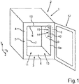
- a household refrigeration appliance 1 In 1 an embodiment of a household refrigeration appliance 1 is shown in a perspective view.
- the household refrigeration appliance 1 is intended to be designed for storing and preserving food.
- the household refrigeration appliance 1 can be a refrigerator or a freezer or a fridge-freezer combination appliance.
- the household refrigeration appliance 1 can be a free-standing household refrigeration appliance or a built-in appliance.
- the household refrigeration appliance 1 has an outer housing 2 .
- the household refrigeration appliance 1 has an inner container 3 . This is separate from the outer housing 2 .
- the inner container 3 is accommodated in the outer case 2 .
- Thermally insulating material 5 is placed in an intermediate space 4 between the outer housing 2 and the inner container 3 .
- the inner container 3 has walls 6, 7, 8, 9 and 10 on. These walls 6 to 10 delimit at least one accommodation space 11 of the household refrigeration appliance 1.
- the accommodation space 11 is intended to accommodate food. It can be a refrigerator compartment or a freezer compartment.
- the household refrigeration appliance 1 also has a door 12 . This is movably arranged on the body, which includes the outer housing 2 and the inner container 3 . As a result, a front loading opening 13 of the inner container 3 can be closed.
- the household refrigeration appliance 1 also has at least one light source module 14 . This is arranged on an inner side 9a of the wall 9 of the inner container 3 facing the receiving space 13 . This position is only to be understood as an example. In addition to or instead of this, a light source module can also be arranged, for example, on an inside of the wall 7 and/or on an inside of the wall 8 and/or on an inside of the wall 6 .
- the wall 9 is provided with a receiving recess 15 on the inside 9a.
- This blind hole-like trough is provided to accommodate the light source module 14 .
- the light source module 14 is therefore arranged countersunk in the wall 9 at least in certain areas.
- In 2 is an enlarged view of portion I in 1 shown. It can be seen that the light source module 14 is designed here as an elongate rail. It is oriented here with a longitudinal axis A in the vertical direction (y-direction) of the household refrigeration appliance 1 .
- the receiving recess 15 is formed to the side in the width direction (x-direction) of the household refrigeration appliance 1 , so that in this respect the light source module 14 is sunk into this receiving recess 15 when viewed in the width direction.
- the light source module 14 has a housing 16 .
- an inner housing wall 17 can be seen in this regard. In the exemplary embodiment, this is exposed towards the receiving space 11 .
- this inner housing wall 17 has a front side 17a. This is the visible side facing the receiving space 11 .
- the inner housing wall 17 is designed here as a plate-like strip.
- the housing 16, as shown in the perspective sectional view in 3 can be seen, an outer housing wall 18 on.
- the outer housing wall 18 is arranged further away from the receiving space 11 than the inner housing wall 17 in this width direction.
- the housing 16 has a connecting wall 19 . This is provided for connecting the inner housing wall 17 and the outer housing wall 18 .
- the housing 16 is U-shaped when viewed perpendicularly to the longitudinal axis A in cross section.
- At least one light source 21 is arranged in the interior 20 of the housing 16 .
- the light source 21 can include a light emitting diode.
- the electronics of the light source module 14 are also arranged in the interior 20 .
- the light source module 16 has a cover 22 .
- the cover 22 is transparent at least in certain areas.
- the cover 22 is designed here as an elongate plate strip.
- This related plate has a front face 23 .
- the front surface 23 faces away from the interior 20 .
- the front surface 23 faces the receiving space 11 .
- the front face 23 is exposed to the receiving space 13 .
- the front surface 23 is a large-surface front side with respect to the strip-shaped plate.
- this cover 22 also has a rear surface 24 .
- the cover 22 also has a marginal edge 25 as provided in a plate-like configuration of a component.
- This marginal edge 25 is a narrow side of the cover 22.
- the marginal edge 25 is designed here as a light exit edge 26, as intended and in accordance with its function. This means that defined and desired light from the light source 21 emerges from this edge 25, which forms the light exit edge 26, as intended.
- this light exit edge 26 is a narrow strip area. This strip surface is smaller, in particular much smaller, than the large surface of the front surface 23 and/or the large surface of the rear surface 24. The surface of the light exit edge 26 extends towards the receiving space 11. It is exposed to the receiving space 11, in particular completely exposed.
- the plane in which the light exit edge 26 extends over a surface area can also be arranged inclined to a plane that is spanned by the height direction and the depth direction of the household refrigeration appliance 1 .
- this plane of the light exit edge 26 can be arranged at an acute angle to the vertical plane and in connection with the loading opening 13 can be oriented toward this acute angle. Due to these light exit edges 26, light is also emitted, as intended, at least in part forwards into the front region of the receiving space 11, in particular also towards the loading opening 13. This light exit edge 26 is arranged so that it is completely exposed towards the receiving space 11 .
- the light exit edge 26 is a vertical surface strip here.
- the cover 22 also has a further opposite marginal edge 27 . This faces the wall 9 . It is not designed and arranged for light emission. In the exemplary embodiment it is provided that the edge 25 and thus the light exit edge 26 is oriented obliquely. Viewed in the depth direction, the edge 25 forms the front end 28 of the cover 22.
- the cover 22 is designed in particular as a diffuser plate or light-scattering plate.
- the cover 22 is oriented with its plate-like element at an angle to the vertical plane.
- the front end 28 of the cover 22 in the depth direction of the household refrigeration appliance 1 is offset further inwards towards the receiving space 11, viewed in the width direction of the household refrigeration appliance 1, than a rear end 29 of the cover 22, viewed in the depth direction.
- the rear end 29 is in particular outer edge 27 formed.
- the front side 17a of the inner housing wall 17 is offset further into the receiving space 11 than the front end 28 of the cover 22.
- the light exit edge 26 is arranged in the width direction at the same width as the front side 17a. In particular, this is provided in each case when the planes of the front side 17a and those of the light exit edge 26 extend in a common plane or in planes parallel to one another.
- the plane in which the light exit edge 26 extends can also be arranged at an angle to the vertical plane. As a result, this plane is also oriented at an angle to the front side 17a. In particular, this light exit edge 26 is then oriented inclined towards the loading opening 13 .
- the outer housing wall 18 has a receptacle 30 .
- the rear or outer end 29 of the cover 22 extends into this receptacle 30.
- this receptacle 30 is formed by an end region of the outer housing wall 18 that is reduced in thickness. As can be seen, the outer edge 27 is completely covered by this receptacle 30 .
- cover 22 protrudes beyond a free end 31 of the inner housing wall 17 viewed in the width direction and thus covers this free end 31 at least in regions.
- the cover 22 has at least one snap-on element 32 . This is snapped into place with at least one counter-snapping element which is arranged on the housing 16 .
- a plurality of snap elements and counter-snap elements are preferably provided.
- the inside or rear surface 24 of the cover 22 rests against the free end or the free edge 31 of the inner housing wall 17 .
- the edge 25 and thus the light exit edge 26 are arranged directly on the front side 17a of the inner housing wall 17 .
- In 4 is the component arrangement in 3 shown in the cutting plane.
- In 4 is in this regard a sectional plane or a horizontal sectional plane shown that is different 3 is.
- the housing 16 has a coupling part 33 .
- This protrudes through a recess 34 in the wall 9, in particular in the receiving recess 15.
- This coupling part 33 thus protrudes into the intermediate space 4.
- a separate backing part or a mounting part 35 is arranged. This allows the light source module 14 to be attached to this mounting part 35 .
- FIG 5 a further exemplary embodiment of a household refrigeration appliance 1 is shown in a perspective sectional view.
- a detail is shown here, in which the wall 7 of the inner container 3 is shown.
- the cover 22 is not completely planar with the faceplate, but the faceplate is angled in relation thereto.
- the front surface 23 is uneven here, in particular angled.
- the surface of the light exit edge 26 extends over a surface area in a vertical plane that is spanned by the depth direction and the height direction.
- an arrangement that is flush with the front side 17a is realized, so that in particular the plane of the front side 17a is the same as the plane of the light exit edge 26 .
- FIG. 7 is in a perspective view accordingly figure 5 and 6 another embodiment of a household refrigeration appliance 1 is shown.
- a different configuration of the cover 22 is again provided. Viewed in the depth direction, the light exit edge 26 is not arranged immediately adjacent to the front side 17a of the inner housing wall 17 . Rather, here the cover 22 is L-shaped when viewed in cross section.
- a first L-leg 37 is arranged so that it rests against the housing 16, respectively an opening of the housing 16 closes or covers. In the exemplary embodiment, this L-leg 37 has no thin light exit edge that would be exposed.
- This cover 22 has a second leg 38 of the L. This is angled and protrudes from the first leg 37 of the L, in particular protrudes away from the housing 16 . An exposed end 39 of this second leg 38 of the L has the edge 25 and thus the light exit edge 26 . This is inclined.
- cover 22 as shown in figure 5 and 6 is shown, with the cover according to FIG 7 is realized.
- a cover 22 then also has a light exit edge 26 or 36 which is exposed to the side or to the front and which, viewed in the depth direction, is formed immediately to the rear adjoining the front side 17a.
- a flush arrangement is preferably provided between the front side 17a and the wall area of the wall 7 or the wall 9 adjoining forward in the depth direction.
- These wall areas 40 ( 3 ) and 41 are shown accordingly.
Landscapes
- Engineering & Computer Science (AREA)
- General Engineering & Computer Science (AREA)
- Chemical & Material Sciences (AREA)
- Combustion & Propulsion (AREA)
- Physics & Mathematics (AREA)
- Mechanical Engineering (AREA)
- Thermal Sciences (AREA)
- Devices That Are Associated With Refrigeration Equipment (AREA)
Applications Claiming Priority (1)
| Application Number | Priority Date | Filing Date | Title |
|---|---|---|---|
| DE102021207579.7A DE102021207579A1 (de) | 2021-07-16 | 2021-07-16 | Haushaltskältegerät mit einem Innenbehälter und einem daran angeordneten Lichtquellenmodul, welches eine spezifische Lichtaustrittskante aufweist |
Publications (2)
| Publication Number | Publication Date |
|---|---|
| EP4119876A1 true EP4119876A1 (fr) | 2023-01-18 |
| EP4119876B1 EP4119876B1 (fr) | 2025-08-20 |
Family
ID=82492785
Family Applications (1)
| Application Number | Title | Priority Date | Filing Date |
|---|---|---|---|
| EP22181740.6A Active EP4119876B1 (fr) | 2021-07-16 | 2022-06-29 | Appareil frigorifique électroménager doté d'un récipient interne et d'un module de source lumineuse disposé sur celui-ci, comportant un bord spécifique de sortie de la lumière |
Country Status (4)
| Country | Link |
|---|---|
| EP (1) | EP4119876B1 (fr) |
| CN (1) | CN115615097A (fr) |
| DE (1) | DE102021207579A1 (fr) |
| PL (1) | PL4119876T3 (fr) |
Families Citing this family (3)
| Publication number | Priority date | Publication date | Assignee | Title |
|---|---|---|---|---|
| DE102024202804A1 (de) * | 2024-03-25 | 2025-09-25 | BSH Hausgeräte GmbH | Haushaltsgerät |
| DE102024202806A1 (de) * | 2024-03-25 | 2025-09-25 | BSH Hausgeräte GmbH | Haushaltsgerät und Leuchte für ein Haushaltsgerät |
| DE102024202805A1 (de) * | 2024-03-25 | 2025-09-25 | BSH Hausgeräte GmbH | Haushaltsgerät und Leuchte für ein Haushaltsgerät |
Citations (3)
| Publication number | Priority date | Publication date | Assignee | Title |
|---|---|---|---|---|
| WO2011108246A1 (fr) * | 2010-03-03 | 2011-09-09 | パナソニック株式会社 | Réfrigérateur |
| JP5197172B2 (ja) * | 2008-06-12 | 2013-05-15 | 三菱電機株式会社 | 冷蔵庫 |
| EP2594880A2 (fr) * | 2011-11-18 | 2013-05-22 | Lg Electronics Inc. | Réfrigérateur |
Family Cites Families (7)
| Publication number | Priority date | Publication date | Assignee | Title |
|---|---|---|---|---|
| US2995649A (en) | 1958-03-26 | 1961-08-08 | Westinghouse Electric Corp | Refrigeration apparatus |
| JP2000258051A (ja) * | 1999-03-03 | 2000-09-22 | Sanyo Electric Co Ltd | 冷蔵庫等の照明装置 |
| JP5620695B2 (ja) | 2010-03-03 | 2014-11-05 | パナソニック株式会社 | 冷蔵庫 |
| CN201892369U (zh) * | 2010-11-12 | 2011-07-06 | 龚央丹 | 一种带有手写荧光显示屏的冰箱 |
| CN202382115U (zh) * | 2011-12-16 | 2012-08-15 | 合肥美菱股份有限公司 | 电冰箱全反射蜂窝式背光led照明灯及电冰箱 |
| CN203501654U (zh) * | 2013-07-30 | 2014-03-26 | 合肥美的电冰箱有限公司 | 一种冰箱内照明灯 |
| CN108534452A (zh) * | 2018-03-21 | 2018-09-14 | 合肥华凌股份有限公司 | 面光源组件及冰箱 |
-
2021
- 2021-07-16 DE DE102021207579.7A patent/DE102021207579A1/de active Pending
-
2022
- 2022-06-29 EP EP22181740.6A patent/EP4119876B1/fr active Active
- 2022-06-29 PL PL22181740.6T patent/PL4119876T3/pl unknown
- 2022-07-14 CN CN202210830728.1A patent/CN115615097A/zh active Pending
Patent Citations (4)
| Publication number | Priority date | Publication date | Assignee | Title |
|---|---|---|---|---|
| JP5197172B2 (ja) * | 2008-06-12 | 2013-05-15 | 三菱電機株式会社 | 冷蔵庫 |
| WO2011108246A1 (fr) * | 2010-03-03 | 2011-09-09 | パナソニック株式会社 | Réfrigérateur |
| EP2594880A2 (fr) * | 2011-11-18 | 2013-05-22 | Lg Electronics Inc. | Réfrigérateur |
| EP2594880B1 (fr) | 2011-11-18 | 2020-10-28 | Lg Electronics Inc. | Réfrigérateur |
Also Published As
| Publication number | Publication date |
|---|---|
| PL4119876T3 (pl) | 2025-12-22 |
| CN115615097A (zh) | 2023-01-17 |
| EP4119876B1 (fr) | 2025-08-20 |
| DE102021207579A1 (de) | 2023-01-19 |
Similar Documents
| Publication | Publication Date | Title |
|---|---|---|
| EP4119876B1 (fr) | Appareil frigorifique électroménager doté d'un récipient interne et d'un module de source lumineuse disposé sur celui-ci, comportant un bord spécifique de sortie de la lumière | |
| EP2059748B1 (fr) | Appareil frigorifique intégré comportant un dispositif de distribution | |
| DE102015007839A1 (de) | Beleuchtungsvorrichtung für ein elektrisches Haushaltsgerät | |
| WO2007093230A1 (fr) | Appareil ménager, notamment appareil ménager à encastrer muni d'un indicateur de fonctionnement commandable | |
| DE102017011959A1 (de) | Flächenleuchtmodul sowie Verfahren zu dessen Montage | |
| DE102018003587A1 (de) | Haushalts-Kühlgerät mit einer Wandleuchte sowie Verfahren zur Herstellung des Kühlgeräts | |
| DE102009033880A1 (de) | Griffanordnung mit gesteuerter Lichtverteilung | |
| EP2662241A2 (fr) | Véhicule comprenant un ciel de toit | |
| EP3008411B1 (fr) | Appareil de froid ménager doté d'un dispositif d'éclairage intérieur et doté d'étagères transparentes | |
| DE102017006424A1 (de) | Leuchtvorrichtung zum Einbau in eine Wandfläche eines elektrischen Geräts der Haushaltsausstattung | |
| WO2018177831A1 (fr) | Appareil ménager comprenant un composant d'appareil qui possède une surface en bande inclinée et un élément structural fonctionnel disposé sur celle-ci | |
| DE102020109934A1 (de) | Kühl- und/oder Gefriergerät mit Außenbeleuchtungskonzept | |
| EP3022505B1 (fr) | Appareil électroménager frigorifique équipé d'au moins une source lumineuse et d'un logement destiné à une clayette | |
| WO2020178119A1 (fr) | Balconnet de rangement pour un appareil de froid ménager pourvu d'une cavité pouvant être éclairée, porte ainsi que dispositif de porte | |
| WO2012168326A1 (fr) | Unité de commande pour un composant de véhicule | |
| DE202010001579U1 (de) | Beleuchtungsvorrichtung für ein bewegliches Möbelelement sowie Möbelelement | |
| EP2787282A1 (fr) | Dispositif d'éclairage de l'espace intérieur d'un appareil ménager et appareil ménager doté d'un tel dispositif d'éclairage | |
| DE102019218222A1 (de) | Haushaltskühlgerät mit einem Vorsprung als Kondenswasser-Tropfleiste in einer Wand eines Eisbereiters | |
| WO2004067320A1 (fr) | Eclairage interieur pour vehicules a moteur | |
| DE102021200494A1 (de) | Haushaltsgerät mit Kamera, die mit einer Blitzlichteinheit und einer Bilderfassungseinheit in einem Frontteil des Kameragehäuses angeordnet ist | |
| EP1816421A2 (fr) | Module d'éclairage pour un appareil électroménager | |
| DE4405721C1 (de) | Leuchte für den Innenraum von Kraftfahrzeugen | |
| DE102022205187A1 (de) | Innenverkleidung mit separaten Innenverkleidungsteilen und einem Lichtsystem an der Verbindungsschnittstelle, sowie Tür | |
| DE102021208921A1 (de) | Beidseitig anschlagbare Tür mit spezifischen Montagebereich und optischer Griffseitenanzeige, sowie Haushaltskältegerät | |
| DE102018108797A1 (de) | Optische Sensorvorrichtung für ein Kraftfahrzeug mit einer Abdeckung und einstückig damit ausgebildetem Abschirmelement |
Legal Events
| Date | Code | Title | Description |
|---|---|---|---|
| PUAI | Public reference made under article 153(3) epc to a published international application that has entered the european phase |
Free format text: ORIGINAL CODE: 0009012 |
|
| STAA | Information on the status of an ep patent application or granted ep patent |
Free format text: STATUS: THE APPLICATION HAS BEEN PUBLISHED |
|
| AK | Designated contracting states |
Kind code of ref document: A1 Designated state(s): AL AT BE BG CH CY CZ DE DK EE ES FI FR GB GR HR HU IE IS IT LI LT LU LV MC MK MT NL NO PL PT RO RS SE SI SK SM TR |
|
| STAA | Information on the status of an ep patent application or granted ep patent |
Free format text: STATUS: REQUEST FOR EXAMINATION WAS MADE |
|
| 17P | Request for examination filed |
Effective date: 20230718 |
|
| RBV | Designated contracting states (corrected) |
Designated state(s): AL AT BE BG CH CY CZ DE DK EE ES FI FR GB GR HR HU IE IS IT LI LT LU LV MC MK MT NL NO PL PT RO RS SE SI SK SM TR |
|
| GRAP | Despatch of communication of intention to grant a patent |
Free format text: ORIGINAL CODE: EPIDOSNIGR1 |
|
| STAA | Information on the status of an ep patent application or granted ep patent |
Free format text: STATUS: GRANT OF PATENT IS INTENDED |
|
| RIC1 | Information provided on ipc code assigned before grant |
Ipc: F25D 23/06 20060101ALI20250310BHEP Ipc: F25D 27/00 20060101AFI20250310BHEP |
|
| INTG | Intention to grant announced |
Effective date: 20250401 |
|
| GRAS | Grant fee paid |
Free format text: ORIGINAL CODE: EPIDOSNIGR3 |
|
| GRAA | (expected) grant |
Free format text: ORIGINAL CODE: 0009210 |
|
| STAA | Information on the status of an ep patent application or granted ep patent |
Free format text: STATUS: THE PATENT HAS BEEN GRANTED |
|
| AK | Designated contracting states |
Kind code of ref document: B1 Designated state(s): AL AT BE BG CH CY CZ DE DK EE ES FI FR GB GR HR HU IE IS IT LI LT LU LV MC MK MT NL NO PL PT RO RS SE SI SK SM TR |
|
| REG | Reference to a national code |
Ref country code: GB Ref legal event code: FG4D Free format text: NOT ENGLISH |
|
| REG | Reference to a national code |
Ref country code: CH Ref legal event code: EP |
|
| REG | Reference to a national code |
Ref country code: DE Ref legal event code: R096 Ref document number: 502022005100 Country of ref document: DE |
|
| REG | Reference to a national code |
Ref country code: IE Ref legal event code: FG4D Free format text: LANGUAGE OF EP DOCUMENT: GERMAN |
|
| REG | Reference to a national code |
Ref country code: NL Ref legal event code: MP Effective date: 20250820 |
|
| PG25 | Lapsed in a contracting state [announced via postgrant information from national office to epo] |
Ref country code: IS Free format text: LAPSE BECAUSE OF FAILURE TO SUBMIT A TRANSLATION OF THE DESCRIPTION OR TO PAY THE FEE WITHIN THE PRESCRIBED TIME-LIMIT Effective date: 20251220 |
|
| PG25 | Lapsed in a contracting state [announced via postgrant information from national office to epo] |
Ref country code: NO Free format text: LAPSE BECAUSE OF FAILURE TO SUBMIT A TRANSLATION OF THE DESCRIPTION OR TO PAY THE FEE WITHIN THE PRESCRIBED TIME-LIMIT Effective date: 20251120 |
|
| REG | Reference to a national code |
Ref country code: LT Ref legal event code: MG9D |
|
| PG25 | Lapsed in a contracting state [announced via postgrant information from national office to epo] |
Ref country code: PT Free format text: LAPSE BECAUSE OF FAILURE TO SUBMIT A TRANSLATION OF THE DESCRIPTION OR TO PAY THE FEE WITHIN THE PRESCRIBED TIME-LIMIT Effective date: 20251222 |
|
| PG25 | Lapsed in a contracting state [announced via postgrant information from national office to epo] |
Ref country code: FI Free format text: LAPSE BECAUSE OF FAILURE TO SUBMIT A TRANSLATION OF THE DESCRIPTION OR TO PAY THE FEE WITHIN THE PRESCRIBED TIME-LIMIT Effective date: 20250820 |
|
| PG25 | Lapsed in a contracting state [announced via postgrant information from national office to epo] |
Ref country code: HR Free format text: LAPSE BECAUSE OF FAILURE TO SUBMIT A TRANSLATION OF THE DESCRIPTION OR TO PAY THE FEE WITHIN THE PRESCRIBED TIME-LIMIT Effective date: 20250820 Ref country code: NL Free format text: LAPSE BECAUSE OF FAILURE TO SUBMIT A TRANSLATION OF THE DESCRIPTION OR TO PAY THE FEE WITHIN THE PRESCRIBED TIME-LIMIT Effective date: 20250820 |
|
| PG25 | Lapsed in a contracting state [announced via postgrant information from national office to epo] |
Ref country code: GR Free format text: LAPSE BECAUSE OF FAILURE TO SUBMIT A TRANSLATION OF THE DESCRIPTION OR TO PAY THE FEE WITHIN THE PRESCRIBED TIME-LIMIT Effective date: 20251121 |
|
| PG25 | Lapsed in a contracting state [announced via postgrant information from national office to epo] |
Ref country code: SE Free format text: LAPSE BECAUSE OF FAILURE TO SUBMIT A TRANSLATION OF THE DESCRIPTION OR TO PAY THE FEE WITHIN THE PRESCRIBED TIME-LIMIT Effective date: 20250820 |
|
| PG25 | Lapsed in a contracting state [announced via postgrant information from national office to epo] |
Ref country code: LV Free format text: LAPSE BECAUSE OF FAILURE TO SUBMIT A TRANSLATION OF THE DESCRIPTION OR TO PAY THE FEE WITHIN THE PRESCRIBED TIME-LIMIT Effective date: 20250820 |
|
| PG25 | Lapsed in a contracting state [announced via postgrant information from national office to epo] |
Ref country code: BG Free format text: LAPSE BECAUSE OF FAILURE TO SUBMIT A TRANSLATION OF THE DESCRIPTION OR TO PAY THE FEE WITHIN THE PRESCRIBED TIME-LIMIT Effective date: 20250820 |
|
| PG25 | Lapsed in a contracting state [announced via postgrant information from national office to epo] |
Ref country code: RS Free format text: LAPSE BECAUSE OF FAILURE TO SUBMIT A TRANSLATION OF THE DESCRIPTION OR TO PAY THE FEE WITHIN THE PRESCRIBED TIME-LIMIT Effective date: 20251120 |
|
| PG25 | Lapsed in a contracting state [announced via postgrant information from national office to epo] |
Ref country code: ES Free format text: LAPSE BECAUSE OF FAILURE TO SUBMIT A TRANSLATION OF THE DESCRIPTION OR TO PAY THE FEE WITHIN THE PRESCRIBED TIME-LIMIT Effective date: 20250820 |
|
| PG25 | Lapsed in a contracting state [announced via postgrant information from national office to epo] |
Ref country code: SM Free format text: LAPSE BECAUSE OF FAILURE TO SUBMIT A TRANSLATION OF THE DESCRIPTION OR TO PAY THE FEE WITHIN THE PRESCRIBED TIME-LIMIT Effective date: 20250820 |
|
| PG25 | Lapsed in a contracting state [announced via postgrant information from national office to epo] |
Ref country code: DK Free format text: LAPSE BECAUSE OF FAILURE TO SUBMIT A TRANSLATION OF THE DESCRIPTION OR TO PAY THE FEE WITHIN THE PRESCRIBED TIME-LIMIT Effective date: 20250820 |
|
| PG25 | Lapsed in a contracting state [announced via postgrant information from national office to epo] |
Ref country code: IT Free format text: LAPSE BECAUSE OF FAILURE TO SUBMIT A TRANSLATION OF THE DESCRIPTION OR TO PAY THE FEE WITHIN THE PRESCRIBED TIME-LIMIT Effective date: 20250820 |
|
| PG25 | Lapsed in a contracting state [announced via postgrant information from national office to epo] |
Ref country code: CZ Free format text: LAPSE BECAUSE OF FAILURE TO SUBMIT A TRANSLATION OF THE DESCRIPTION OR TO PAY THE FEE WITHIN THE PRESCRIBED TIME-LIMIT Effective date: 20250820 |
|
| PG25 | Lapsed in a contracting state [announced via postgrant information from national office to epo] |
Ref country code: EE Free format text: LAPSE BECAUSE OF FAILURE TO SUBMIT A TRANSLATION OF THE DESCRIPTION OR TO PAY THE FEE WITHIN THE PRESCRIBED TIME-LIMIT Effective date: 20250820 Ref country code: SK Free format text: LAPSE BECAUSE OF FAILURE TO SUBMIT A TRANSLATION OF THE DESCRIPTION OR TO PAY THE FEE WITHIN THE PRESCRIBED TIME-LIMIT Effective date: 20250820 |