EP4119884B1 - Chargeur multicanal pour pistolet jouet - Google Patents
Chargeur multicanal pour pistolet jouet Download PDFInfo
- Publication number
- EP4119884B1 EP4119884B1 EP22180297.8A EP22180297A EP4119884B1 EP 4119884 B1 EP4119884 B1 EP 4119884B1 EP 22180297 A EP22180297 A EP 22180297A EP 4119884 B1 EP4119884 B1 EP 4119884B1
- Authority
- EP
- European Patent Office
- Prior art keywords
- magazine
- channels
- housing
- channel
- bullets
- Prior art date
- Legal status (The legal status is an assumption and is not a legal conclusion. Google has not performed a legal analysis and makes no representation as to the accuracy of the status listed.)
- Active
Links
Images


Classifications
-
- F—MECHANICAL ENGINEERING; LIGHTING; HEATING; WEAPONS; BLASTING
- F41—WEAPONS
- F41A—FUNCTIONAL FEATURES OR DETAILS COMMON TO BOTH SMALLARMS AND ORDNANCE, e.g. CANNONS; MOUNTINGS FOR SMALLARMS OR ORDNANCE
- F41A9/00—Feeding or loading of ammunition; Magazines; Guiding means for the extracting of cartridges
- F41A9/61—Magazines
-
- F—MECHANICAL ENGINEERING; LIGHTING; HEATING; WEAPONS; BLASTING
- F41—WEAPONS
- F41B—WEAPONS FOR PROJECTING MISSILES WITHOUT USE OF EXPLOSIVE OR COMBUSTIBLE PROPELLANT CHARGE; WEAPONS NOT OTHERWISE PROVIDED FOR
- F41B11/00—Compressed-gas guns, e.g. air guns; Steam guns
- F41B11/50—Magazines for compressed-gas guns; Arrangements for feeding or loading projectiles from magazines
- F41B11/55—Magazines for compressed-gas guns; Arrangements for feeding or loading projectiles from magazines the projectiles being stored in stacked order in a removable box magazine, rack or tubular magazine
-
- F—MECHANICAL ENGINEERING; LIGHTING; HEATING; WEAPONS; BLASTING
- F41—WEAPONS
- F41A—FUNCTIONAL FEATURES OR DETAILS COMMON TO BOTH SMALLARMS AND ORDNANCE, e.g. CANNONS; MOUNTINGS FOR SMALLARMS OR ORDNANCE
- F41A9/00—Feeding or loading of ammunition; Magazines; Guiding means for the extracting of cartridges
- F41A9/61—Magazines
- F41A9/64—Magazines for unbelted ammunition
- F41A9/65—Box magazines having a cartridge follower
- F41A9/69—Box magazines having a cartridge follower characterised by multiple-row or zigzag arrangement of cartridges
Definitions
- the disclosure relates to a magazine for a toy gun, and more particularly to a multi-channel magazine for receiving and holding bullets.
- a conventional magazine disclosed in JP 2005106302 generally includes a bullet outlet, an accommodating space for filling and receiving numerous bullets, an alignment slot extending toward the bullet outlet for arranging the bullets closely and alternately packed in two rows therein, a moving port in spacial communication with the accommodating space and the alignment slot, and a spring-biased pressing unit disposed in the alignment slot to press the bullets.
- the accommodating space is fixed in dimension, which cannot meet any requirement of usage.
- an object of the disclosure is to provide a multi-channel magazine that can alleviate at least one of the drawbacks of the prior art.
- the bullets can be moved and converged gradually to a one-by-one arrangement in one row to the bullet outlet, which facilitates smooth pressing and discharging of the bullets and increases the capacity of magazine.
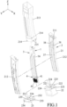
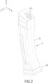
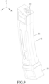
- an embodiment of a multi-channel magazine for a toy gun is adapted to receive numerous bullets 1 and includes a magazine body 2, a dividing unit 3 and a bullet pressing unit 4.
- the magazine body 2 is elongated in a lengthwise direction (Z), and includes a magazine housing 21, an expansion housing 22 and a magazine cap 23.
- the magazine housing 21 includes two magazine body halves 212 which are coupled with each other to define a bullet outlet 211 therebetween, and an outer sleeve 213 which surrounds and is sleeved around the magazine body halves 212.
- the bullet outlet 211 is formed at an end face to discharge the bullets 1 therefrom.
- the outer sleeve 213 has two protrusions 214 which are respectively formed at two sides thereof in a front-rear direction (Y), and two grooves 215 which are formed at an end thereof and opposite to the protrusions 214 in a width direction (X) and further opposite to the bullet outlet 211 in the lengthwise direction (Z).
- the lengthwise direction (Z), the width direction (X) and the front-rear direction (Y) are perpendicular to one another.
- the expansion housing 22 has a first sleeve 222 of a U-shape which defines a first mounting opening 221 for sleeving on the magazine housing 21 from the first mounting opening 221, two first hooks 223 which are formed on an inner surface of the first sleeve 222 to be respectively engageable with the grooves 215, two first slots 224 which are formed in the inner surface of the first sleeve 222 to be respectively engageable with the protrusions 214, and four expansion channels 225 which are opened toward one side thereof.
- the magazine cap 23 has a second sleeve 232 of a U-shape which defines a second mounting opening 231 for sleeving on the magazine housing 21 from the second mounting opening 231, two second hooks 233 which are formed on an inner surface of the second sleeve 232 to be respectively engageable with the grooves 215, two second slots 234 which are formed in the inner surface of the second sleeve 232 to be respectively engageable with the protrusions 214, and a wall 235 which extends transverse to the second sleeve 232.
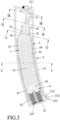
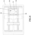
- the dividing unit 3 is formed within the magazine housing 21 and cooperates with the magazine housing 21 to define within the magazine housing 21 a converging channel 31 which is in spacial communication with the bullet outlet 211, a plurality of storage channels 32 (the number of the storage channels 32 is S) which extend in the lengthwise direction (Z), a plurality of first narrow channels 33 (the number of the first narrow channels 33 is M) which are in spacial communication with the storage channels 32, and a plurality of second narrow channels 34 (the number of the second narrow channels 34 is N) which are formed downstream of the first narrow channels 33 and upstream of the converging channel 31.
- the storage channels 32 are configured to arrange the bullets 1 filled and held therein in the width direction (X) such that a plurality of rows of the bullets 1 (the number of rows of the bullets 1 is R) are arranged in the storage channels 32.
- each of the first narrow channels 33, the second narrow channels 34 and the converging channel 31 has a width configured to allow only one of the bullets 1 to pass through.
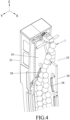
- the dividing unit 3 includes a dividing plate 36 which is disposed within and divides the magazine housing 21 into two half compartments 35, and two dividing ribs 37 which extend transversely from the dividing plate 36 and each of which divides a respective one of the half compartments 35 into two of the storage channels 32.
- the dividing unit 3 further includes four guiding rib assemblies 38. Each guiding rib assembly 38 extends from at least one of the magazine housing 21 and the dividing plate 36 in the front-rear direction (Y), and has a plurality of rib portions arranged in the lengthwise direction (Z).
- Each two of the guiding rib assemblies 38 are disposed within the corresponding half compartment 35 and are spaced apart from the corresponding dividing rib 37 in the width direction (X) to cooperate with the corresponding dividing rib 37 to define within the corresponding half compartment 35 two of the first narrow channels 33 and one of the second narrow channels 34. Specifically, the two of the guiding rib assemblies 38 extend and are converged toward each other to define within the corresponding half compartment 35 the second narrow channel 34.
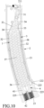
- the bullet pressing unit 4 is mounted on the magazine body 2, and includes four pressing elements 41 and four biasing elements 42. Each pressing element 41 is adapted to press the bullets 1. Each biasing element 42 is disposed between the magazine body 2 and the respective pressing element 41 to urge the corresponding pressing element 41 to move toward the bullet outlet 211.
- each pressing element 41 is movably disposed in the respective storage channel 32, and each biasing element 42 is disposed between and abuts against the respective pressing element 41 and the wall 235 of the magazine cap 23.
- the pressing elements 41 press the bullets 1 from the storage channels 32 through the first and second narrow channels 33, 34 and discharge the bullets 1 from the converging channel 31.
- the eight rows of the bullets 1 arranged in the storage channels 32 enter the first narrow channels 33 and are arranged to four rows.
- the four rows of the bullets 1 in the first narrow channels 33 enter the second narrow channels 34 and are arranged to two rows.
- the two rows of the bullets 1 in the second narrow channels 34 enter the converging channel 31 and are converged in one row.
- the bullets 1 are discharged one by one from the bullet outlet 211.
- the magazine cap 23 when the magazine cap 23 is mounted on the magazine housing 21, the magazine cap 23 is connected with the magazine housing 21 in the front-rear direction (Y) from the second mounting opening 231 while the second hooks 233 are engaged with the grooves 215 and the second slots 234 are engaged with the protrusions 214 for the magazine cap 23 to be securely sleeved on the magazine housing 21.
- the magazine cap 23 is forced in a direction away from the magazine housing 21 to disengage the second hooks 233 and second slots 234 from the grooves 215 and the protrusions 214 for the magazine cap 23 to be removed from the magazine housing 21.
- each expansion channel 225 is in spacial communication with the respective storage channel 32
- each pressing element 41 is movably disposed in the respective expansion channel 225 and the respective storage channel 32
- each biasing element 42 is disposed between the respective pressing element 41 and the expansion housing 22 .
- the pressing elements 41 press the bullets 1 by virtue of the biasing action of the biasing elements 42 from the expansion channels 225 and through the storage channels 32, the first narrow channels 33 and the second narrow channels 34, and the bullets 1 then enter the converging channel 31 to be discharged from the bullet outlet 211.
- the pressing elements 41 and the biasing elements 42 are respectively moved down into the expansion channels 225 from the storage channels 32 when the expansion housing 22 is mounted on and connected with the magazine housing 21.
- the pressing elements 41 and the biasing elements 42 may be removed from the magazine housing 21 when the magazine cap 23 is detached from the magazine housing 21, and are moved into the expansion channels 225 of the expansion housing 22.
- the expansion housing 22 when the expansion housing 22 is mounted on the magazine housing 21, the expansion housing 22 is connected with the magazine housing 21 in the front-rear direction (Y) from the first mounting opening 221 while the first hooks 223 are engaged with the grooves 215 and the first slots 224 are engaged with the protrusions 214 for the expansion housing 22 to be securely sleeved on the magazine housing 21.
- the expansion housing 22 is forced in a direction away from the magazine housing 21 to disengage the first hooks 223 and the first slots 224 from the grooves 215 and the protrusions 214 for the expansion housing 22 to be removed from the magazine housing 21.
- the number of the storage channels 32 and the expansion channels 225 may not be limited to four. In other embodiments, it may be two, three or more than four.
- the capacity of the magazine is increased.
- the bullets 1 can be pressed toward the bullet outlet 211 without the need to frequently fill bullets in the magazine so as to decrease the times of bullet filling operation.
- the first narrow channels 33 and the second narrow channels 34 eight rows of the bullets 1 can be rearranged and converged to four rows in the first narrow channels 33, and then to two rows in the second narrow channels 34.
- the bullets 1 can be moved and converged gradually to a one-by-one arrangement in one row in the converging channel 31, which can avoid jostling of the bullets 1 against one another to smoothly press and discharge the bullets 1. Furthermore, with the expansion housing 22 and the movable pressing unit 4, the magazine housing 21 is selectively connected with one of the magazine cap 23 and the expansion housing 22 to meet the capacity requirement of usage.
Landscapes
- Engineering & Computer Science (AREA)
- General Engineering & Computer Science (AREA)
- Toys (AREA)
Claims (8)
- Chargeur multicanal pour pistolet jouet adapté pour recevoir de nombreuses munitions sphériques (1), comprenant :un corps de chargeur (2) allongé dans une direction longitudinale (Z), et comportant une sortie de munitions (211),une unité de division (3) formée à l'intérieur dudit corps de chargeur (2), etune unité de pression de munitions (4) montée sur ledit corps de chargeur (2), caractérisé en ce que :ladite unité de division (3) coopère avec ledit corps de chargeur (2) pour définir une pluralité de canaux de stockage (32) à l'intérieur dudit corps de chargeur (2), lesquels s'étendent dans la direction longitudinale (Z), une pluralité de premiers canaux étroits (33) en communication spatiale avec lesdits canaux de stockage (32), un canal convergeant (31) formé en aval desdits premiers canaux étroits (33) et en communication spatiale avec ladite sortie de munitions (211), et une pluralité de deuxièmes canaux étroits (34) formés en aval desdits premiers canaux étroits (33) et en amont dudit canal convergeant (31), chacun parmi lesdits canaux de stockage (32) étant configuré pour agencer les munitions (1) contenues dans celui-ci dans une direction de largeur (X) de telle façon qu'une pluralité de rangées de munitions (1) sont agencées dans chacun desdits canaux de stockage (32), chacun parmi lesdits premiers canaux étroits (33), lesdits deuxièmes canaux étroits (34) et ledit canal convergeant (31) présentant une largeur configurée pour permettre uniquement le passage de l'une des munitions (1), le nombre desdits premiers canaux étroits (33) étant de M, le nombre de rangées de munitions (1) dans chacun desdits canaux de stockage (32) étant de R, le nombre desdits canaux de stockage (32) étant de S, le nombre desdits deuxièmes canaux étroits (34) étant de N, dans lequel chacun parmi M, N et R est pair, R > S > N, et S = M ;ladite unité de pression de munitions (4) pressant les munitions (1) à partir desdits canaux de stockage (32) à travers lesdits premiers canaux étroits (33) et lesdits deuxièmes canaux étroits (34) et déchargeant les munitions à partir dudit canal convergeant (31).
- Chargeur multicanal selon la revendication 1, caractérisé en ce que ladite unité de division (3) inclut une plaque de division (36) disposée à l'intérieur dudit corps de chargeur (2) et divisant celui-ci en deux demi-compartiments (35), et deux nervures de division (37) s'étendant transversalement à partir de ladite plaque de division (36) et parmi lesquelles chacune divise l'un respectif desdits demi-compartiments (35) en deux desdits canaux de stockage (32) .
- Chargeur multicanal selon la revendication 2, caractérisé en ce que ladite unité de division (3) inclut en outre quatre ensembles de nervures de guidage (38), chacun desdits ensembles de nervures de guidage (38) s'étendant à partir de l'un au moins parmi ledit corps de chargeur (2) et ladite plaque de division (36) dans une direction avant-arrière (Y), deux desdits ensembles de nervures de guidage (38) étant disposés à l'intérieur de l'un respectif desdits demi-compartiments (35) et espacé de l'une correspondantes desdites nervures de division (37) dans la direction de largeur (X) pour coopérer avec ladite nervure de division (37) correspondante afin de définir deux desdits premiers canaux étroits (33) à l'intérieur dudit demi-compartiment (35) correspondant, la direction longitudinale (Z), la direction de largeur (X) et ladite direction avant-arrière (Y) étant perpendiculaires les unes aux autres.
- Chargeur multicanal selon la revendication 3, caractérisé en ce que lesdits deux parmi lesdits ensembles de nervures de guidage (38) s'étendent et pointent l'un vers l'autre pour définir l'un desdits deuxièmes canaux étroits (34) à l'intérieur dudit demi-compartiment (35) correspondant, ladite unité de pression de munitions (4) incluant une pluralité d'éléments de pression (41) et une pluralité d'éléments de sollicitation (42), chacun desdits éléments de pression (41) étant disposé dans l'un respectif desdits canaux de stockage (32), chacun desdits éléments de sollicitation (42) étant disposé entre ledit corps de chargeur (2) et l'un respectif desdits éléments de pression (41) pour forcer ledit élément de pression (41) correspondant à se déplacer vers ladite sortie de munitions (211) .
- Chargeur multicanal selon la revendication 1, caractérisé en ce que ledit corps de chargeur (2) inclut un logement de chargeur (21), un logement d'expansion (22) et un capuchon de chargeur (23), ledit logement de chargeur (21) comportant ladite sortie de munitions (211), chacun parmi ledit logement d'expansion (22) et ledit capuchon de chargeur (23) étant monté sur et relié sélectivement et de façon amovible audit logement de chargeur (21) dans la direction longitudinale (Z), ledit logement d'expansion (22) définissant une pluralité de canaux d'expansion (225) dans celui-ci, lesquels sont ouverts vers un côté de celui-ci, ladite unité de pression de munitions (4) incluant une pluralité d'éléments de pression (41) et une pluralité d'éléments de sollicitation (42), dans lequel, lorsque ledit logement d'expansion (22) est relié audit logement de chargeur (21) et monté sur celui-ci, lesdits canaux d'expansion (225) sont en communication spatiale avec lesdits canaux de stockage (32), respectivement, chacun desdits éléments de pression (41) est disposé de façon déplaçable dans l'un respectif desdits canaux d'expansion (225) et l'un respectif desdits canaux de stockage (32), et chacun desdits éléments de sollicitation (42) est disposé entre l'un respectif desdits éléments de pression (41) et ledit logement d'expansion (22), et dans lequel, lorsque ledit capuchon de chargeur (23) est relié au logement de chargeur (21) et monté sur celui-ci, chacun desdits éléments de pression (41) est disposé de façon déplaçable dans l'un respectif desdits canaux de stockage (32), et chacun desdits éléments de sollicitation (42) est disposé entre l'un respectif desdits éléments de pression (41) et ledit capuchon de chargeur (23).
- Chargeur multicanal selon la revendication 5, caractérisé en ce que chacun desdits éléments de sollicitation (42) est disposé de façon déplaçable dans l'un respectif desdits canaux d'expansion (225) et l'un respectif desdits canaux de stockage (32).
- Chargeur multicanal selon la revendication 5, caractérisé en ce que ledit logement de chargeur (21) comporte en outre deux saillies (214) formées respectivement sur deux côtés de celui-ci dans une direction avant-arrière (Y), et au moins une rainure (215) formée à une extrémité de celui-ci et opposée auxdites saillies (214) dans la direction de largeur (X), ladite au moins une rainure (215) étant espacée de ladite sortie de munitions (211) dans la direction longitudinale (Z), ledit logement d'expansion (22) comportant un premier manchon (222) définissant une première ouverture de montage (221) pour le manchonnage sur ledit logement de chargeur (21) depuis ladite première ouverture de montage (221), au moins un premier crochet (223) formé sur une surface intérieure dudit premier manchon (222) pour l'engagement avec ladite rainure (215), et deux premières fentes (224) formées dans ladite surface intérieure dudit premier manchon (222) pour l'engagement respectif avec lesdites saillies (214), la direction longitudinale (Z), la direction de largeur (X) et la direction avant-arrière (Y) étant perpendiculaires les unes aux autres.
- Chargeur multicanal selon la revendication 7, caractérisé en ce que ledit capuchon de chargeur (23) comporte un deuxième manchon (232) définissant une deuxième ouverture de montage (231) pour le manchonnage sur ledit logement de chargeur (21) depuis ladite deuxième ouverture de montage (231), au moins un deuxième crochet (233) formé sur une surface intérieure dudit deuxième manchon (232) pour l'engagement avec ladite rainure (215), deux deuxièmes fentes (234) formées dans ladite surface intérieure dudit deuxième manchon (232) pour l'engagement respectif avec lesdites saillies (214), et une paroi (235) s'étendant transversalement audit deuxième manchon (232) pour la butée desdits éléments de sollicitation (42) contre celle-ci.
Applications Claiming Priority (1)
| Application Number | Priority Date | Filing Date | Title |
|---|---|---|---|
| TW110125516A TWI790678B (zh) | 2021-07-12 | 2021-07-12 | 玩具槍的多彈道式彈匣 |
Publications (3)
| Publication Number | Publication Date |
|---|---|
| EP4119884A1 EP4119884A1 (fr) | 2023-01-18 |
| EP4119884C0 EP4119884C0 (fr) | 2024-07-31 |
| EP4119884B1 true EP4119884B1 (fr) | 2024-07-31 |
Family
ID=82214182
Family Applications (1)
| Application Number | Title | Priority Date | Filing Date |
|---|---|---|---|
| EP22180297.8A Active EP4119884B1 (fr) | 2021-07-12 | 2022-06-22 | Chargeur multicanal pour pistolet jouet |
Country Status (7)
| Country | Link |
|---|---|
| US (1) | US11859938B2 (fr) |
| EP (1) | EP4119884B1 (fr) |
| JP (1) | JP7407468B2 (fr) |
| CN (1) | CN115615240A (fr) |
| ES (1) | ES2988269T3 (fr) |
| PL (1) | PL4119884T3 (fr) |
| TW (1) | TWI790678B (fr) |
Families Citing this family (1)
| Publication number | Priority date | Publication date | Assignee | Title |
|---|---|---|---|---|
| US12332013B2 (en) * | 2023-04-28 | 2025-06-17 | Xcal Ip Llc | Firearm with dual feed magazine |
Family Cites Families (24)
| Publication number | Priority date | Publication date | Assignee | Title |
|---|---|---|---|---|
| GB573429A (en) * | 1940-12-31 | 1945-11-21 | Josef Vesely | Improvements in or relating to magazines for fire arms |
| US2503116A (en) * | 1944-06-22 | 1950-04-04 | Brevets Aero Mecaniques | Ammunition charging device for automatic arms |
| US3204361A (en) * | 1964-02-03 | 1965-09-07 | John G Rocha | Large capacity magazine for firearms |
| US3345771A (en) * | 1966-01-07 | 1967-10-10 | Stanley D Silsby | High capacity magazine and cooperating firearm structure |
| US3672089A (en) * | 1969-08-13 | 1972-06-27 | Us Army | Large capacity magazine |
| US3788191A (en) * | 1972-12-06 | 1974-01-29 | Gen Electric | Burst firing, single barrel, armament |
| US4428137A (en) * | 1981-10-13 | 1984-01-31 | Johnson James H | Cartridge magazine |
| DE3422334A1 (de) * | 1984-06-15 | 1985-12-19 | Sites S.p.A., Mondovi, Cuneo | Patronenmagazin fuer feuerwaffen |
| JP2004239531A (ja) * | 2003-02-06 | 2004-08-26 | Ponyland:Kk | 玩具用空気銃の弾倉マガジン |
| JP2005106302A (ja) | 2003-09-26 | 2005-04-21 | Tokyo Marui:Kk | 球形弾用マガジン |
| US20060180134A1 (en) * | 2005-02-11 | 2006-08-17 | Illuzzi Louis M | Combination solid projectile and paintball gun, and solid projectile adapter for paintball gun |
| US20070261688A1 (en) | 2005-12-15 | 2007-11-15 | Tam Wai Kee P | Semi-Automatic Magazine and Method of Ammunition Loading |
| CN200952919Y (zh) * | 2006-04-21 | 2007-09-26 | 张驰 | 玩具枪用弹匣机构 |
| CN102906530B (zh) * | 2010-03-25 | 2016-02-17 | 西部装备有限责任公司 | 高容量弹匣 |
| BR112012023713B1 (pt) | 2010-03-25 | 2021-05-18 | ArmWest, LLC | carregador, arma de fogo, e método |
| CN202928445U (zh) * | 2012-11-22 | 2013-05-08 | 张敬 | 四排供弹弹匣 |
| TWI424142B (zh) * | 2013-02-01 | 2014-01-21 | 巨大塑膠工業有限公司 | Toy gun magazine pushball structure |
| US8839706B1 (en) * | 2013-03-05 | 2014-09-23 | Real Action Paintball (RAPY) | Drum magazine for projectiles |
| US10317153B2 (en) * | 2016-07-11 | 2019-06-11 | Sagi Faifer | Apparatus and method for increasing capacity of an ammunition magazine |
| UA117181C2 (uk) * | 2016-12-07 | 2018-06-25 | Гліб Георгійович Макаров | Магазин для стрілецької зброї |
| TWM547659U (zh) * | 2016-12-09 | 2017-08-21 | Guay Guay Trading Co Ltd | 彈匣之倒立擊發結構 |
| US10488143B2 (en) * | 2017-08-29 | 2019-11-26 | Hasbro, Inc. | Rapid fire toy launch apparatus |
| HRP20180652A2 (hr) | 2018-04-24 | 2019-11-01 | Erwin Bekto | Spremnik municije velikog kapaciteta |
| CN109579609A (zh) * | 2018-12-13 | 2019-04-05 | 重庆工业职业技术学院 | 一种75发大容量弹匣 |
-
2021
- 2021-07-12 TW TW110125516A patent/TWI790678B/zh active
-
2022
- 2022-06-22 CN CN202210708220.4A patent/CN115615240A/zh active Pending
- 2022-06-22 PL PL22180297.8T patent/PL4119884T3/pl unknown
- 2022-06-22 JP JP2022099970A patent/JP7407468B2/ja active Active
- 2022-06-22 EP EP22180297.8A patent/EP4119884B1/fr active Active
- 2022-06-22 US US17/846,545 patent/US11859938B2/en active Active
- 2022-06-22 ES ES22180297T patent/ES2988269T3/es active Active
Also Published As
| Publication number | Publication date |
|---|---|
| US11859938B2 (en) | 2024-01-02 |
| ES2988269T3 (es) | 2024-11-19 |
| TWI790678B (zh) | 2023-01-21 |
| TW202303082A (zh) | 2023-01-16 |
| JP2023011510A (ja) | 2023-01-24 |
| US20230010513A1 (en) | 2023-01-12 |
| JP7407468B2 (ja) | 2024-01-04 |
| EP4119884C0 (fr) | 2024-07-31 |
| EP4119884A1 (fr) | 2023-01-18 |
| CN115615240A (zh) | 2023-01-17 |
| PL4119884T3 (pl) | 2025-02-10 |
Similar Documents
| Publication | Publication Date | Title |
|---|---|---|
| EP4119884B1 (fr) | Chargeur multicanal pour pistolet jouet | |
| US10996010B2 (en) | Locking system for removable magazine floor plates for firearm magazines | |
| US10337811B1 (en) | Overmold firearm charging handle | |
| US7797871B2 (en) | Magazine for a firearm | |
| EP0665109B1 (fr) | Réservoir d'encre avec plusieurs éléments poreux pour stocker l'encre et dispositif à jet d'encre avec ce réservoir d'encre | |
| US20100209759A1 (en) | Battery pack | |
| CA3164989C (fr) | Chargeur consommable pour un pistolet-jouet | |
| EP3821197A1 (fr) | Magasin pour arme à feu | |
| KR20210090938A (ko) | 배터리 팩 | |
| US20140125742A1 (en) | Ink Cartridge for Printer | |
| JP2026504420A (ja) | 電池パック | |
| EP3312928B1 (fr) | Pile rechargeable au lithium-ion | |
| US6390616B2 (en) | Method for manufacturing ink cartridges | |
| EP4404360A1 (fr) | Soupape de régulation de la pression pour module de stockage d'électricité | |
| US20240066883A1 (en) | Remanufacturing method of ink cartridge, and remanufactured ink cartridge | |
| US20100128095A1 (en) | Print cartridge | |
| US11787191B2 (en) | Liquid container and method of manufacturing the same | |
| US20250201964A1 (en) | Heat exchange assembly | |
| US7396117B2 (en) | Liquid container and liquid ejecting cartridge | |
| CN216409914U (zh) | 弹匣托弹部分控制结构 | |
| US20060082624A1 (en) | Ink cartridge usable with a wide array type printer head | |
| CN222507734U (zh) | 换热组件、电池包和车辆 | |
| EP4611122A1 (fr) | Dispositif de refroidissement de liquide, ensemble de communication et bloc-batterie | |
| CN214124035U (zh) | 平衡车的电池仓、电池模块和平衡车 | |
| KR101751431B1 (ko) | 잉크 정압 공급장치 |
Legal Events
| Date | Code | Title | Description |
|---|---|---|---|
| PUAI | Public reference made under article 153(3) epc to a published international application that has entered the european phase |
Free format text: ORIGINAL CODE: 0009012 |
|
| STAA | Information on the status of an ep patent application or granted ep patent |
Free format text: STATUS: REQUEST FOR EXAMINATION WAS MADE |
|
| 17P | Request for examination filed |
Effective date: 20220622 |
|
| AK | Designated contracting states |
Kind code of ref document: A1 Designated state(s): AL AT BE BG CH CY CZ DE DK EE ES FI FR GB GR HR HU IE IS IT LI LT LU LV MC MK MT NL NO PL PT RO RS SE SI SK SM TR |
|
| GRAP | Despatch of communication of intention to grant a patent |
Free format text: ORIGINAL CODE: EPIDOSNIGR1 |
|
| STAA | Information on the status of an ep patent application or granted ep patent |
Free format text: STATUS: GRANT OF PATENT IS INTENDED |
|
| RIC1 | Information provided on ipc code assigned before grant |
Ipc: F41A 9/69 20060101ALI20240108BHEP Ipc: F41B 11/55 20130101AFI20240108BHEP |
|
| INTG | Intention to grant announced |
Effective date: 20240124 |
|
| RAP3 | Party data changed (applicant data changed or rights of an application transferred) |
Owner name: GUAY GUAY TRADING CO., LTD. |
|
| GRAS | Grant fee paid |
Free format text: ORIGINAL CODE: EPIDOSNIGR3 |
|
| GRAA | (expected) grant |
Free format text: ORIGINAL CODE: 0009210 |
|
| STAA | Information on the status of an ep patent application or granted ep patent |
Free format text: STATUS: THE PATENT HAS BEEN GRANTED |
|
| AK | Designated contracting states |
Kind code of ref document: B1 Designated state(s): AL AT BE BG CH CY CZ DE DK EE ES FI FR GB GR HR HU IE IS IT LI LT LU LV MC MK MT NL NO PL PT RO RS SE SI SK SM TR |
|
| REG | Reference to a national code |
Ref country code: CH Ref legal event code: EP Ref country code: GB Ref legal event code: FG4D |
|
| REG | Reference to a national code |
Ref country code: DE Ref legal event code: R096 Ref document number: 602022004921 Country of ref document: DE |
|
| REG | Reference to a national code |
Ref country code: IE Ref legal event code: FG4D |
|
| U01 | Request for unitary effect filed |
Effective date: 20240821 |
|
| U07 | Unitary effect registered |
Designated state(s): AT BE BG DE DK EE FI FR IT LT LU LV MT NL PT RO SE SI Effective date: 20240902 |
|
| REG | Reference to a national code |
Ref country code: ES Ref legal event code: FG2A Ref document number: 2988269 Country of ref document: ES Kind code of ref document: T3 Effective date: 20241119 |
|
| PG25 | Lapsed in a contracting state [announced via postgrant information from national office to epo] |
Ref country code: NO Free format text: LAPSE BECAUSE OF FAILURE TO SUBMIT A TRANSLATION OF THE DESCRIPTION OR TO PAY THE FEE WITHIN THE PRESCRIBED TIME-LIMIT Effective date: 20241031 |
|
| PG25 | Lapsed in a contracting state [announced via postgrant information from national office to epo] |
Ref country code: GR Free format text: LAPSE BECAUSE OF FAILURE TO SUBMIT A TRANSLATION OF THE DESCRIPTION OR TO PAY THE FEE WITHIN THE PRESCRIBED TIME-LIMIT Effective date: 20241101 |
|
| PG25 | Lapsed in a contracting state [announced via postgrant information from national office to epo] |
Ref country code: IS Free format text: LAPSE BECAUSE OF FAILURE TO SUBMIT A TRANSLATION OF THE DESCRIPTION OR TO PAY THE FEE WITHIN THE PRESCRIBED TIME-LIMIT Effective date: 20241130 |
|
| PG25 | Lapsed in a contracting state [announced via postgrant information from national office to epo] |
Ref country code: HR Free format text: LAPSE BECAUSE OF FAILURE TO SUBMIT A TRANSLATION OF THE DESCRIPTION OR TO PAY THE FEE WITHIN THE PRESCRIBED TIME-LIMIT Effective date: 20240731 |
|
| PG25 | Lapsed in a contracting state [announced via postgrant information from national office to epo] |
Ref country code: RS Free format text: LAPSE BECAUSE OF FAILURE TO SUBMIT A TRANSLATION OF THE DESCRIPTION OR TO PAY THE FEE WITHIN THE PRESCRIBED TIME-LIMIT Effective date: 20241031 |
|
| PG25 | Lapsed in a contracting state [announced via postgrant information from national office to epo] |
Ref country code: RS Free format text: LAPSE BECAUSE OF FAILURE TO SUBMIT A TRANSLATION OF THE DESCRIPTION OR TO PAY THE FEE WITHIN THE PRESCRIBED TIME-LIMIT Effective date: 20241031 Ref country code: NO Free format text: LAPSE BECAUSE OF FAILURE TO SUBMIT A TRANSLATION OF THE DESCRIPTION OR TO PAY THE FEE WITHIN THE PRESCRIBED TIME-LIMIT Effective date: 20241031 Ref country code: IS Free format text: LAPSE BECAUSE OF FAILURE TO SUBMIT A TRANSLATION OF THE DESCRIPTION OR TO PAY THE FEE WITHIN THE PRESCRIBED TIME-LIMIT Effective date: 20241130 Ref country code: HR Free format text: LAPSE BECAUSE OF FAILURE TO SUBMIT A TRANSLATION OF THE DESCRIPTION OR TO PAY THE FEE WITHIN THE PRESCRIBED TIME-LIMIT Effective date: 20240731 Ref country code: GR Free format text: LAPSE BECAUSE OF FAILURE TO SUBMIT A TRANSLATION OF THE DESCRIPTION OR TO PAY THE FEE WITHIN THE PRESCRIBED TIME-LIMIT Effective date: 20241101 |
|
| PG25 | Lapsed in a contracting state [announced via postgrant information from national office to epo] |
Ref country code: SM Free format text: LAPSE BECAUSE OF FAILURE TO SUBMIT A TRANSLATION OF THE DESCRIPTION OR TO PAY THE FEE WITHIN THE PRESCRIBED TIME-LIMIT Effective date: 20240731 |
|
| PG25 | Lapsed in a contracting state [announced via postgrant information from national office to epo] |
Ref country code: CZ Free format text: LAPSE BECAUSE OF FAILURE TO SUBMIT A TRANSLATION OF THE DESCRIPTION OR TO PAY THE FEE WITHIN THE PRESCRIBED TIME-LIMIT Effective date: 20240731 |
|
| PG25 | Lapsed in a contracting state [announced via postgrant information from national office to epo] |
Ref country code: SK Free format text: LAPSE BECAUSE OF FAILURE TO SUBMIT A TRANSLATION OF THE DESCRIPTION OR TO PAY THE FEE WITHIN THE PRESCRIBED TIME-LIMIT Effective date: 20240731 |
|
| PLBE | No opposition filed within time limit |
Free format text: ORIGINAL CODE: 0009261 |
|
| STAA | Information on the status of an ep patent application or granted ep patent |
Free format text: STATUS: NO OPPOSITION FILED WITHIN TIME LIMIT |
|
| 26N | No opposition filed |
Effective date: 20250501 |
|
| U20 | Renewal fee for the european patent with unitary effect paid |
Year of fee payment: 4 Effective date: 20250616 |
|
| PGFP | Annual fee paid to national office [announced via postgrant information from national office to epo] |
Ref country code: ES Payment date: 20250710 Year of fee payment: 4 |
|
| PGFP | Annual fee paid to national office [announced via postgrant information from national office to epo] |
Ref country code: PL Payment date: 20250618 Year of fee payment: 4 |
|
| REG | Reference to a national code |
Ref country code: CH Ref legal event code: H13 Free format text: ST27 STATUS EVENT CODE: U-0-0-H10-H13 (AS PROVIDED BY THE NATIONAL OFFICE) Effective date: 20260127 |
|
| PG25 | Lapsed in a contracting state [announced via postgrant information from national office to epo] |
Ref country code: MC Free format text: LAPSE BECAUSE OF FAILURE TO SUBMIT A TRANSLATION OF THE DESCRIPTION OR TO PAY THE FEE WITHIN THE PRESCRIBED TIME-LIMIT Effective date: 20240731 |
|
| PG25 | Lapsed in a contracting state [announced via postgrant information from national office to epo] |
Ref country code: IE Free format text: LAPSE BECAUSE OF NON-PAYMENT OF DUE FEES Effective date: 20250622 |
|
| PG25 | Lapsed in a contracting state [announced via postgrant information from national office to epo] |
Ref country code: CH Free format text: LAPSE BECAUSE OF NON-PAYMENT OF DUE FEES Effective date: 20250630 |