EP4119902A1 - Kalibrierungsbügel - Google Patents
Kalibrierungsbügel Download PDFInfo
- Publication number
- EP4119902A1 EP4119902A1 EP21775802.8A EP21775802A EP4119902A1 EP 4119902 A1 EP4119902 A1 EP 4119902A1 EP 21775802 A EP21775802 A EP 21775802A EP 4119902 A1 EP4119902 A1 EP 4119902A1
- Authority
- EP
- European Patent Office
- Prior art keywords
- component
- base
- cross beam
- stand
- vertical rod
- Prior art date
- Legal status (The legal status is an assumption and is not a legal conclusion. Google has not performed a legal analysis and makes no representation as to the accuracy of the status listed.)
- Granted
Links
Images

Classifications
-
- F—MECHANICAL ENGINEERING; LIGHTING; HEATING; WEAPONS; BLASTING
- F16—ENGINEERING ELEMENTS AND UNITS; GENERAL MEASURES FOR PRODUCING AND MAINTAINING EFFECTIVE FUNCTIONING OF MACHINES OR INSTALLATIONS; THERMAL INSULATION IN GENERAL
- F16M—FRAMES, CASINGS OR BEDS OF ENGINES, MACHINES OR APPARATUS, NOT SPECIFIC TO ENGINES, MACHINES OR APPARATUS PROVIDED FOR ELSEWHERE; STANDS; SUPPORTS
- F16M11/00—Stands or trestles as supports for apparatus or articles placed thereon ; Stands for scientific apparatus such as gravitational force meters
- F16M11/02—Heads
- F16M11/04—Means for attachment of apparatus; Means allowing adjustment of the apparatus relatively to the stand
- F16M11/043—Allowing translations
- F16M11/046—Allowing translations adapted to upward-downward translation movement
-
- G—PHYSICS
- G01—MEASURING; TESTING
- G01D—MEASURING NOT SPECIALLY ADAPTED FOR A SPECIFIC VARIABLE; ARRANGEMENTS FOR MEASURING TWO OR MORE VARIABLES NOT COVERED IN A SINGLE OTHER SUBCLASS; TARIFF METERING APPARATUS; MEASURING OR TESTING NOT OTHERWISE PROVIDED FOR
- G01D18/00—Testing or calibrating apparatus or arrangements provided for in groups G01D1/00 - G01D15/00
-
- F—MECHANICAL ENGINEERING; LIGHTING; HEATING; WEAPONS; BLASTING
- F16—ENGINEERING ELEMENTS AND UNITS; GENERAL MEASURES FOR PRODUCING AND MAINTAINING EFFECTIVE FUNCTIONING OF MACHINES OR INSTALLATIONS; THERMAL INSULATION IN GENERAL
- F16M—FRAMES, CASINGS OR BEDS OF ENGINES, MACHINES OR APPARATUS, NOT SPECIFIC TO ENGINES, MACHINES OR APPARATUS PROVIDED FOR ELSEWHERE; STANDS; SUPPORTS
- F16M11/00—Stands or trestles as supports for apparatus or articles placed thereon ; Stands for scientific apparatus such as gravitational force meters
- F16M11/02—Heads
- F16M11/18—Heads with mechanism for moving the apparatus relatively to the stand
-
- F—MECHANICAL ENGINEERING; LIGHTING; HEATING; WEAPONS; BLASTING
- F16—ENGINEERING ELEMENTS AND UNITS; GENERAL MEASURES FOR PRODUCING AND MAINTAINING EFFECTIVE FUNCTIONING OF MACHINES OR INSTALLATIONS; THERMAL INSULATION IN GENERAL
- F16M—FRAMES, CASINGS OR BEDS OF ENGINES, MACHINES OR APPARATUS, NOT SPECIFIC TO ENGINES, MACHINES OR APPARATUS PROVIDED FOR ELSEWHERE; STANDS; SUPPORTS
- F16M11/00—Stands or trestles as supports for apparatus or articles placed thereon ; Stands for scientific apparatus such as gravitational force meters
- F16M11/20—Undercarriages with or without wheels
- F16M11/2007—Undercarriages with or without wheels comprising means allowing pivoting adjustment
- F16M11/2014—Undercarriages with or without wheels comprising means allowing pivoting adjustment around a vertical axis
-
- F—MECHANICAL ENGINEERING; LIGHTING; HEATING; WEAPONS; BLASTING
- F16—ENGINEERING ELEMENTS AND UNITS; GENERAL MEASURES FOR PRODUCING AND MAINTAINING EFFECTIVE FUNCTIONING OF MACHINES OR INSTALLATIONS; THERMAL INSULATION IN GENERAL
- F16M—FRAMES, CASINGS OR BEDS OF ENGINES, MACHINES OR APPARATUS, NOT SPECIFIC TO ENGINES, MACHINES OR APPARATUS PROVIDED FOR ELSEWHERE; STANDS; SUPPORTS
- F16M11/00—Stands or trestles as supports for apparatus or articles placed thereon ; Stands for scientific apparatus such as gravitational force meters
- F16M11/20—Undercarriages with or without wheels
- F16M11/24—Undercarriages with or without wheels changeable in height or length of legs, also for transport only, e.g. by means of tubes screwed into each other
- F16M11/26—Undercarriages with or without wheels changeable in height or length of legs, also for transport only, e.g. by means of tubes screwed into each other by telescoping, with or without folding
- F16M11/28—Undercarriages for supports with one single telescoping pillar
-
- F—MECHANICAL ENGINEERING; LIGHTING; HEATING; WEAPONS; BLASTING
- F16—ENGINEERING ELEMENTS AND UNITS; GENERAL MEASURES FOR PRODUCING AND MAINTAINING EFFECTIVE FUNCTIONING OF MACHINES OR INSTALLATIONS; THERMAL INSULATION IN GENERAL
- F16M—FRAMES, CASINGS OR BEDS OF ENGINES, MACHINES OR APPARATUS, NOT SPECIFIC TO ENGINES, MACHINES OR APPARATUS PROVIDED FOR ELSEWHERE; STANDS; SUPPORTS
- F16M11/00—Stands or trestles as supports for apparatus or articles placed thereon ; Stands for scientific apparatus such as gravitational force meters
- F16M11/20—Undercarriages with or without wheels
- F16M11/24—Undercarriages with or without wheels changeable in height or length of legs, also for transport only, e.g. by means of tubes screwed into each other
- F16M11/38—Undercarriages with or without wheels changeable in height or length of legs, also for transport only, e.g. by means of tubes screwed into each other by folding, e.g. pivoting or scissors tong mechanisms
-
- F—MECHANICAL ENGINEERING; LIGHTING; HEATING; WEAPONS; BLASTING
- F16—ENGINEERING ELEMENTS AND UNITS; GENERAL MEASURES FOR PRODUCING AND MAINTAINING EFFECTIVE FUNCTIONING OF MACHINES OR INSTALLATIONS; THERMAL INSULATION IN GENERAL
- F16M—FRAMES, CASINGS OR BEDS OF ENGINES, MACHINES OR APPARATUS, NOT SPECIFIC TO ENGINES, MACHINES OR APPARATUS PROVIDED FOR ELSEWHERE; STANDS; SUPPORTS
- F16M11/00—Stands or trestles as supports for apparatus or articles placed thereon ; Stands for scientific apparatus such as gravitational force meters
- F16M11/42—Stands or trestles as supports for apparatus or articles placed thereon ; Stands for scientific apparatus such as gravitational force meters with arrangement for propelling the support stands on wheels
-
- F—MECHANICAL ENGINEERING; LIGHTING; HEATING; WEAPONS; BLASTING
- F16—ENGINEERING ELEMENTS AND UNITS; GENERAL MEASURES FOR PRODUCING AND MAINTAINING EFFECTIVE FUNCTIONING OF MACHINES OR INSTALLATIONS; THERMAL INSULATION IN GENERAL
- F16M—FRAMES, CASINGS OR BEDS OF ENGINES, MACHINES OR APPARATUS, NOT SPECIFIC TO ENGINES, MACHINES OR APPARATUS PROVIDED FOR ELSEWHERE; STANDS; SUPPORTS
- F16M7/00—Details of attaching or adjusting engine beds, frames, or supporting-legs on foundation or base; Attaching non-moving engine parts, e.g. cylinder blocks
-
- G—PHYSICS
- G01—MEASURING; TESTING
- G01D—MEASURING NOT SPECIALLY ADAPTED FOR A SPECIFIC VARIABLE; ARRANGEMENTS FOR MEASURING TWO OR MORE VARIABLES NOT COVERED IN A SINGLE OTHER SUBCLASS; TARIFF METERING APPARATUS; MEASURING OR TESTING NOT OTHERWISE PROVIDED FOR
- G01D11/00—Component parts of measuring arrangements not specially adapted for a specific variable
- G01D11/30—Supports specially adapted for an instrument; Supports specially adapted for a set of instruments
-
- G—PHYSICS
- G01—MEASURING; TESTING
- G01M—TESTING STATIC OR DYNAMIC BALANCE OF MACHINES OR STRUCTURES; TESTING OF STRUCTURES OR APPARATUS, NOT OTHERWISE PROVIDED FOR
- G01M13/00—Testing of machine parts
-
- G—PHYSICS
- G01—MEASURING; TESTING
- G01M—TESTING STATIC OR DYNAMIC BALANCE OF MACHINES OR STRUCTURES; TESTING OF STRUCTURES OR APPARATUS, NOT OTHERWISE PROVIDED FOR
- G01M17/00—Testing of vehicles
-
- F—MECHANICAL ENGINEERING; LIGHTING; HEATING; WEAPONS; BLASTING
- F16—ENGINEERING ELEMENTS AND UNITS; GENERAL MEASURES FOR PRODUCING AND MAINTAINING EFFECTIVE FUNCTIONING OF MACHINES OR INSTALLATIONS; THERMAL INSULATION IN GENERAL
- F16M—FRAMES, CASINGS OR BEDS OF ENGINES, MACHINES OR APPARATUS, NOT SPECIFIC TO ENGINES, MACHINES OR APPARATUS PROVIDED FOR ELSEWHERE; STANDS; SUPPORTS
- F16M2200/00—Details of stands or supports
- F16M2200/02—Locking means
- F16M2200/021—Locking means for rotational movement
Definitions
- the present application relates to the technical field of vehicle maintenance and equipment calibration, and in particular to a calibration bracket.
- ADAS An advanced driver assistant system, referred to as ADAS, is an active safety technology to use a variety of sensors mounted to a vehicle to collect environmental data inside and outside the vehicle immediately, and perform technical processing such as the identification, detection, and tracking of static and dynamic objects, so as to enable a driver to detect a possible danger at the fastest time, so as to draw attention and improve the safety.
- ADAS uses sensors such as cameras, radars, lasers, ultrasonic waves, etc. to detect light, heat, pressure, or other variables used to monitor the condition of the vehicle.
- the sensors are typically on the front and rear bumpers, side-view mirrors, the inside of a steering column, or a windshield.
- vibrations, collisions, ambient temperature and humidity, etc. may change the physical installation state of the above-mentioned sensors so that an adjustment or a calibration needs to be performed irregularly.
- a calibration element is usually mounted to a calibration bracket so as to adjust or calibrate a sensor on the vehicle.
- it is necessary to accurately position the calibration element relative to the sensor on the vehicle. It is necessary not only to position the calibration element at a pre-set position relative to the sensor on the vehicle, but also to adjust the angle of the calibration element relative to the sensor on the vehicle. For example, the case that two opposite faces of the calibration element and the sensor on the vehicle need to be adjusted to be parallel, or at a certain angle, etc. Because the positions of the sensors on the vehicle are different, and the mounting positions of the calibration element on the calibration bracket are different, how to flexibly adjust the angle of the calibration element relative to the vehicle becomes a subject to be studied by a person skilled in the art.
- Embodiments of the present invention are intended to provide a calibration bracket that facilitates the adjustment of the angle of rotation of a cross beam relative to the central axis of a stand component.
- the rotating component comprises a support seat, a rotating base, and a stand base, wherein the support seat is mounted to the base, the rotating base is rotatably connected to the support seat, the stand base is fixed to the rotating base, and the stand base is fixedly connected to the stand component for supporting the stand component; wherein the rotating base is pivotable relative to the base about the central axis of the stand component to drive the stand component to pivot relative to the base about the central axis of the stand component through the stand base.
- the rotating component further comprises a first thrust bearing and a second thrust bearing, wherein the first thrust bearing is mounted to the support seat, and the second thrust bearing is mounted to the rotating base; the second thrust bearing is rotatable relative to the first thrust bearing such that the rotating base is rotatable relative to the support seat.
- the rotating component further comprises a connecting shaft component located at an axial connecting line of the first thrust bearing and the second thrust bearing for fixing an axial direction of the first thrust bearing and the second thrust bearing as the central axis of the stand component.
- the rotating component further comprises a limiting member for limiting a rotational angle of the rotating base relative to the support seat.
- the limiting member comprises a first limiting member and a second limiting member, one of the first limiting member and the second limiting member being mounted to the support seat, and the other of the first limiting member and the second limiting member being mounted to the rotating base; the rotating base is fixed relative to the support seat when the first limiting member cooperates with the second limiting member.
- the first limiting member is a locking portion, and the second limiting member is a locking knob;
- the rotating base is rotatable relative to the support seat within a radian range of the arc-shaped through hole when the locking knob does not cooperate with the locking portion; the locking knob may be used to fix the rotating base at any position within the radian range relative to the support seat.
- a radian scale is provided beside the arc-shaped through hole for assisting in identifying a rotational angle of the rotating base.
- the cross beam component may be mounted at any of at least two height positions of the stand component.
- the stand component comprises a fixed vertical rod and a movable vertical rod
- the cross beam component may be mounted to the movable vertical rod or the fixed vertical rod; when the cross beam component is mounted to the movable vertical rod, the cross beam component can be driven by the movable vertical rod to move relative to the fixed vertical rod along the length direction of the fixed vertical rod.
- the cross beam component comprises a first cross beam portion, a second cross beam portion, and a connecting portion; the connecting portion is mounted to the stand component, one end of the connecting portion being pivotably connected to the first cross beam portion, and the other end of the connecting portion being pivotably connected to the second cross beam portion.
- the present invention also provides a calibration bracket comprising: a base;
- the calibration bracket further comprises a rotating component mounted between the stand component and the base for driving the stand component to pivot relative to the base about the central axis of the stand component.
- the rotating component comprises a support seat, a rotating base, and a stand base, wherein the support seat is mounted to the base, the rotating base is rotatably connected to the support seat, the stand base is fixed to the rotating base, and the stand base is fixedly connected to the stand component for supporting the stand component; wherein the rotating base is pivotable relative to the base about the central axis of the stand component to drive the stand component to pivot relative to the base about the central axis of the stand component through the stand base.
- the rotating component further comprises a first thrust bearing and a second thrust bearing, wherein the first thrust bearing is mounted to the support seat, and the second thrust bearing is mounted to the rotating base; the second thrust bearing is rotatable relative to the first thrust bearing such that the rotating base is rotatable relative to the support seat.
- the rotating component further comprises a connecting shaft component located at an axial connecting line of the first thrust bearing and the second thrust bearing for fixing an axial direction of the first thrust bearing and the second thrust bearing as the central axis of the stand component.
- the rotating component further comprises a limiting member for limiting a rotational angle of the rotating base relative to the support seat.
- the limiting member comprises a first limiting member and a second limiting member, one of the first limiting member and the second limiting member being mounted to the support seat, and the other of the first limiting member and the second limiting member being mounted to the rotating base; the rotating base is fixed relative to the support seat when the first limiting member cooperates with the second limiting member.
- the first limiting member is a locking portion, and the second limiting member is a locking knob;
- the rotating base is rotatable relative to the support seat within a radian range of the arc-shaped through hole when the locking knob does not cooperate with the locking portion; the locking knob may be used to fix the rotating base at any position within the radian range relative to the support seat.
- a radian scale is provided beside the arc-shaped through hole for assisting in identifying a rotational angle of the rotating base.
- the cross beam component may be mounted at any of at least two height positions of the stand component.
- the stand component comprises a fixed vertical rod and a movable vertical rod
- the cross beam component may be mounted to the movable vertical rod or the fixed vertical rod; when the cross beam component is mounted to the movable vertical rod, the cross beam component can be driven by the movable vertical rod to move relative to the fixed vertical rod along the length direction of the fixed vertical rod.
- the cross beam component comprises a first cross beam portion, a second cross beam portion, and a connecting portion; the connecting portion is mounted to the stand component, one end of the connecting portion being pivotably connected to the first cross beam portion, and the other end of the connecting portion being pivotably connected to the second cross beam portion.
- the rotational angle of the cross beam component relative to the central axis of the stand component is adjusted by driving the stand component to pivot relative to the base about the central axis of the stand component, so that the rotation of the cross beam component is free from the mounting position.
- the calibration bracket is simple in structure, and convenient to carry.
- orientational or positional relationships indicated by the terms “upper”, “lower”, “inner”, “outer”, “vertical”, “horizontal”, and the like are based on the orientational or positional relationships shown in the drawings, and are merely for the convenience in describing and simplifying the present invention, and do not indicate or imply that the referenced devices or elements must have a particular orientation, be constructed and operated in a particular orientation, and thus are not to be construed as limiting the present invention.
- first”, “second”, and the like are used for descriptive purposes only and are not to be construed as indicating or implying relative importance.
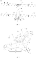
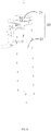
- an embodiment of the present invention provides a calibration bracket 100 comprising a base 10, a stand component 20, a cross beam component 30, 30', and a rotating component 40.
- the stand component 20 is connected to the base 10; the cross beam component is mounted to the stand component 20; the cross beam component is used to mount a calibration element for calibrating an advanced assistant driver system of the vehicle; the rotating component 40 is mounted between the stand component 20 and the base 10 for driving the stand component 20 to pivot relative to the base 10 about the central axis of the stand component 20 to adjust the rotational angle of the cross member component relative to the central axis of the stand component 20.
- mounting includes welding, screwing, clamping, gluing, etc. to fix or limit a certain element or device to a specific position or place.
- the element or device may be fixed in a specific position or place or may be movable within a limited range.
- the element or device may or may not be detachable after being fixed or limited to a specific position or place, which is not limited by the embodiments of the present invention.
- the connecting portion 36 of the cross beam component 30 is mounted above the stand component 20, such as the upper cross beam component 30 shown in Fig. 1 .
- the connecting portion may be otherwise supported by the stand component 20.
- the connecting portion 36' of the cross beam component may be mounted to an appropriate side face of the stand component 20, such as the lower cross beam component 30' shown in Fig. 1 .
- support or “supporting” refers to bearing the weight of an element or a device such that it does not move downward due to its own weight.
- the cross beam component 30 may be used to mount a calibration element, such as a multi-line laser, a calibration target (a calibration plate or a calibration pattern plate), a radar reflecting or absorbing device, etc. to calibrate an on-board driver assistant system.
- the cross beam component 30 may co-support or mount the calibration element in combination with the stand component so as to enable the calibration element to be stably mounted to the calibration bracket.
- the cross beam component 30 can be mounted to the upper end of the stand component 20 for mounting a calibration element corresponding to a sensor located higher up in the vehicle, such as a calibration target for calibrating an image acquisition device on a front window of the vehicle; and the other being that the cross beam component 30' may be mounted to the lower end of the stand component 20 for mounting a calibration element corresponding to a sensor located lower down in the vehicle, such as a radar calibration plate for calibrating an adaptive cruise control system near two headlights of the vehicle.
- upper end or “lower end” are used to describe the relative positions of the two cross beam components and are not intended to limit the specific position at which the cross beam component is mounted to the stand component 20.
- the cross beam component shown in Fig. 1 includes one upper end or lower end that can be mounted to the stand component 20, or the cross beam component includes two cross beam components mountable to both the upper end and the lower end of the stand component 20 at the same time, thereby enabling the simultaneous calibration of different equipment on the vehicle.
- the cross beam component whether mounted to the upper end of the stand component 20 or to the lower end of the stand component 20, can move in the vertical direction relative to the stand component 20 to enable the mounted calibration elements to be located at different heights so as to accommodate the calibration of an advanced assistant driver systems on different types of vehicles. Further, the cross beam component may move relative to the stand component 20 within a defined height range.
- the cross beam component may rotate relative to the stand component 20, e.g. the case that the cross beam component may be pivotable about an axis perpendicular to the cross beam component and the stand component, i.e. the cross beam component may be pivotable about the axis until the cross beam component coincides with the stand component in the vertical direction, thereby reducing the volume of the calibration bracket during the transportation and, in use, pivoting the cross beam component to the horizontal direction.
- the cross beam component can only rotate within a defined range relative to the stand component to adjust the cross beam component to the horizontal direction, wherein the cross beam component in the horizontal direction refers to a parallel direction of the cross beam component relative to a support face, such as a ground surface, for supporting the vehicle and the calibration bracket.
- the adjustment of the angle of the cross beam component in the horizontal direction is used primarily to accurately position the calibration element on the cross beam so that the face of the calibration element facing the vehicle can be more accurately aligned with the equipment to be calibrated on the vehicle. It will be understood that the adjustment of the angle of the cross beam component relative to the horizontal direction may also be achieved by means of a mechanism on the base or stand component, which is not limited herein.
- connection mode of the cross beam component and the stand component is not limited as long as it can enable the scenario that the cross beam component and the stand component can be moved relative to each other or mounted in the manner mentioned above.
- the first cross beam portion 32 and the second cross beam portion 34 pivotably rotate relative to the connecting portion 36, respectively. Folding the cross beam component 30 can reduce the volume of the calibration bracket 100 to facilitate shipping.
- the cross beam component may comprise other implementation modes, such as a cross beam having a long length as shown in the figure, so as to enable the range of mounting of the calibration element to be widened, which can be applicable to the calibration of various types of vehicles.
- the cross beam component comprises a cross beam having a short length, which is only used for supporting the calibration element. If it is necessary to move the calibration element to a certain position, this can be achieved by a calibration bracket; alternatively, the cross beam component only includes a connecting mechanism to the stand component, the calibration element being mounted to the connecting mechanism.
- the angle of the calibration element towards the face of the equipment to be calibrated can be adjusted.
- the adjustment of the angle of the cross beam component toward the face of the vehicle is achieved by providing a mechanism of the cross beam component and the stand component bracket.
- such implementation mode is obviously less fast and convenient and requires multiple adjustments when the position of the cross beam component on the stand component changes, or when two cross beam components are mounted to the stand component.
- an embodiment of the present application provides an adjustment mechanism between the base and the stand component, such as the rotating component 40 shown in Fig. 1 , capable of adjusting the angle of rotation of the stand component 20 about its central axis in the vertical direction, thereby enabling more flexible and convenient adjustment of the angle of the cross beam relative to the vehicle.
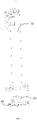
- the base 10 includes a base body 12, a roller 14, and a height adjustment member 16.
- the base body 12 has a triangular claw shape, and includes three claws, each extending in three different directions.
- the base body 12 may be made of a metallic material.
- the roller 14 is mounted at the bottom surface of the base body 12, and the number of the rollers 14 may be three, and each of the rollers 14 is mounted at the end of one corresponding claw for facilitating the movement of the base body 12.
- the roller 14 is a universal moving roller so that the base body 12 can move back and forth, and left and right randomly.
- the height adjustment member 16 is mounted to the base body 12 for adjusting the height of the base body 12.
- the height adjustment members 16 are adjusting knobs, the number of which is three. At least one section of a spiral rod is included below the knob, and the spiral rod is engaged with a threaded through hole at the base body 12 to enable height adjustment.
- Each height adjustment member 16 is mounted to one corresponding claw and close to one corresponding roller 14.
- Three height adjustment members 16 are a regular triangular distribution.
- the height adjustment member 16 can be adjusted so that the height adjustment member 16 is in contact with the ground. Therefore, the base 10 can be prevented from sliding under the driving of the roller 14 when the cross beam component 30 or the stand component 20 needs to adjust the rotational angle.
- the shape of the base body 12 may vary according to actual needs and is not limited to a triangular claw shape.
- the base body 12 may be rectangular or circular.
- the number of the rollers 14 and the height adjustment members 16 may be respectively increased or decreased according to actual requirements.
- the height adjustment members can be two, and one stand bar with a fixed height is coordinated to adjust the angle of the base body 12.
- the rotating component 40 is mounted to the base 10.
- the rotating component 40 may be detachably mounted to the base 10, e.g. the case that the rotating component 40 may be mounted to the base 10 by means of a captive screw 50, so as to facilitate quick fixing or removal of the rotating component 40 to or from the base 10.
- the rotating component 40 can be mounted to the calibration bracket 100 as a fitting.
- the rotating component 40 can be mounted; otherwise, the rotating component 40 need not be mounted.
- the rotating component 40 may be fixedly mounted to the base 10.
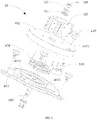
- the rotating component 40 comprises a support seat 401 detachably mounted to the base body 12, a rotating base 402 rotatably connected to the support seat 401, and a stand base 403 fixed to the rotating base 402 by means of a screw or the like, the stand base 403 being fixedly connected to the stand component 20 for supporting the stand component 20.
- the rotating base 402 can pivot relative to the base 10 about the central axis L of the stand component 20 to drive the stand component 20 to pivot relative to the base 10 about the central axis L of the stand component 20 via the stand base 403, thereby adjusting the rotational angle of the cross beam component 30 relative to the central axis L of the stand component 20.
- the stand base 403 is adapted to the shape of the junction of the stand component 20.
- the stand base 403 is a hollow structure to reduce the weight of the calibration bracket 100.
- the stand base 403 is received at the bottom of the stand component 20 and the stand component 20 and the stand base 403 are fixed by a screw.
- the internal dimension of the hollow region of the stand base 403 may also be larger than the peripheral dimension of the end of the stand component 20 such that the end of the stand component 20 is inserted into the hollow region of the stand base 403 and then the stand component 20 is fixed to the stand base 403 by a screw.
- the rotating component 40 further comprises a first thrust bearing 404 and a second thrust bearing 405.
- the first thrust bearing 404 is mounted to the support seat 401
- the rotating base 402 is inversely mounted to the first thrust bearing 404
- the second thrust bearing 405 is mounted to the rotating base 402.
- the second thrust bearing 405 is rotatable relative to the first thrust bearing 404 such that the rotating base 402 is rotatable relative to the support seat 401.
- the inversing mounting means that the opening of the rotating base 402 is downward, and the inner surface of the rotating base 402 covers the first thrust bearing 404.
- the rotating base 402 may be rotatable relative to the support seat 401 by other rotational mechanisms.
- the rotating base 402 is fixedly provided with a rotary shaft in the direction of the support seat 401
- the support seat 401 is fixedly provided with a sleeve for the rotary shaft to rotate
- the axis of the rotary shaft is consistent with the central axis of the stand component.
- the rotating base 402 can rotate relative to the support seat 401.
- the support seat 401 is fixedly provided with a rotary shaft to the rotating base 402, and the rotating base 402 is fixedly provided with a sleeve for the rotary shaft to rotate.
- the rotating base 402 can rotate relative to the support seat 401.
- the rotating component 40 further comprises a connecting shaft component located at the axial connecting line of the first thrust bearing 404 and the second thrust bearing 405 for fixing the axial direction of the first thrust bearing 404 and the second thrust bearing 405 as the central axis L of the stand component 20.
- the connecting shaft component comprises a connecting shaft 406, a washer 407, and a lock nut 408.
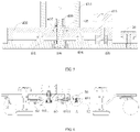
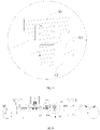
- Both the support seat 401 and the rotating base 402 are provided with a hole through which the connecting shaft 406 passes. As shown in Fig. 5 , the bottom end of the connecting shaft 406 is fixed to the bottom of the support seat 401 via a screw.
- the connecting shaft 406 passes through the support seat 401, the first thrust bearing 404, the rotating base 402, and the second thrust bearing 405 in sequence, and extends into the hollow structure of the stand base 403.
- the washer 407 and the lock nut 408 are mounted to the top end of the connecting shaft 406, and the connecting shaft 406 is axially limited on the rotating base 402 via the lock nut 408, the washer 407, and the second thrust bearing 405.
- the bottom of the support seat 401 is provided with a groove for receiving the bottom end of the connecting shaft 406 so that the bottom end of the connecting shaft 406 is not exposed to the support seat 401 when being fixed to the bottom of the support seat 401.
- the rotating component 40 further includes a limiting member for limiting the rotational angle of the rotating base 402 relative to the support seat 401, i.e. it is to limit the rotational angle of the stand component 20 relative to the central axis L.
- the limiting member comprises a first limiting member and a second limiting member.
- One of the first limiting member and the second limiting member is mounted to the support seat 401, and the other of the first limiting member and the second limiting member is mounted to the rotating base 402.
- the rotating base 402 is fixed relative to the support seat 401.
- the first limiting member cooperating with the second limiting member means that the first limiting member and the second limiting member generate a connecting relationship to mutually fix the positions of each other so as to enable the relative positions of the rotating base 402 and the support seat 401 to be fixed, thereby limiting the rotational angle of the stand component 20 relative to the central axis L.
- the first limiting member and the second limiting member do not cooperate, which means that the first limiting member and the second limiting member have not yet generated a connecting relationship, and thus cannot fix the positions of each other.
- the first limiting member is a locking portion 409
- the second limiting member is a locking knob 410
- the locking portion 409 is received between the rotating base 402 and the support seat 401 and is fixedly mounted to the support seat 401.
- the rotating base 402 is provided with an arc-shaped through hole 4021 so that the locking knob 410 passes through the arc-shaped through hole 4021 and then cooperates with the locking portion 409, such as threaded locking so that the rotating base 402 is fixed relative to the support seat 401.
- first limiting member and the second limiting member can also cooperate in other ways, for example, the case that the first limiting member is an elastic clip, the second limiting member is a snap, and the clip is locked with the snap, so that the rotating base 402 is fixed relative to the support seat 401.
- the rotating base 402 can rotate relative to the support seat 401 within the radian range of the arc-shaped through hole 4021, so that the stand component 20 is driven to rotate about the central axis L of the stand component 20 by the stand base 403, so as to adjust the rotational angle of the cross beam component 30 relative to the central axis L of the stand component 20.
- rotating the cross beam component 30 or rotating the stand component 20 can drive the rotating base 402 to rotate relative to the support seat 401 within the radian range of the arc-shaped through hole 4021.
- the range in which the rotating base 402 can rotate is the radian range of the arc-shaped through hole 4021, which starts from one end of the second limiting member located at the arc-shaped through hole 4021, and ends from the other end of the second limiting member located at the arc-shaped through hole 4021. That is, within this range, the first limiting member cooperates with the second limiting member, otherwise, the rotating base 402 covers the first limiting member, and the second limiting member cannot cooperate with the first limiting member to get fixed.
- a radian scale may be provided next to the arc-shaped through hole 4021 of the upper surface of the rotating base 402 (i.e. the surface on which the stand base 403 is mounted).
- the radian scale may be used to assist in identifying the angle of the rotating base 402 as it rotates.
- the locking knob 410 may be used to fix the rotating base 402 at any position within the radian range relative to the support seat 401. That is, when the rotating base 402 rotates to a certain required position, the locking knob 410 can be connected to the locking portion 409 by means of screw-threaded coupling by passing through the arc-shaped through hole 4021, thereby fixing the rotating base 402 relative to the support seat 401.
- the rotating base 402 may limit the angle of rotation with the support seat 401 by other limiting means.
- the first limiting member provided on the inner surface of the rotating base 402 cooperates with the second limiting member mounted to the circumferential surface of the first thrust bearing to limit the rotational angle; or the first limiting member is provided on a surface of the rotating base 402 in contact with the support seat 401, and the second limiting member is provided on the support seat 401; or the first limiting member is provided on the outer surface of the rotating base 402, and the second limiting member is provided on the support seat 401.
- the base body 12 and the support seat 401 are both provided with a threaded hole adapted to the captive screw 50.
- the support seat 401 is fixed to the base 10 via the captive screw 50.
- the support seat 401 is in the shape of a disk as a whole, three claws are formed extending from the disk in three different directions, the included angle between two adjacent claws is 120 degrees, and the three claws are respectively provided with a threaded hole adapted to the captive screw 50.
- two pins 60 are provided on the base body 12, and two pin holes 4011 are provided on the support seat 401 at positions corresponding to the two pins 60.
- the support seat 401 cannot fit with the base body 12; if the pin hole 4011 is aligned with the pin 60 and the angle between the pin hole 4011 and the pin 60 differs by 180°, the captive screw 50 cannot be screwed into the threaded hole of the base body 12 corresponding to the captive screw 50, i.e. the rotating component 40 cannot be mounted to the base 10.
- the stand component 20 includes a fixed vertical rod 22 mounted to the rotating component 40 and a movable vertical rod 24.
- the fixed vertical rod 22 and the movable vertical rod 24 coincide with the central axis of the rotating component 40.
- the movable vertical rod 24 is sleeved in the fixed vertical rod 22, and the movable vertical rod 24 can move relative to the fixed vertical rod 22 only along the length direction of the fixed vertical rod 22.
- the fixed vertical rod 22 and the movable vertical rod 24 are respectively square tubes, and the movable vertical rod 24 is closely sleeved in the fixed vertical rod 22 so that the movable vertical rod 24 can only move relative to the fixed vertical rod 22 along the length direction of the fixed vertical rod 22, and the movable vertical rod 24 can be prevented from moving relative to the fixed vertical rod 22 in other directions.
- the height of the stand component 20 can be reduced to nearly half of the original height by means of sleeving and connecting the movable vertical rod 24 and the fixed vertical rod 22 so that it is convenient for carrying.
- one driving mechanism may be mounted to the fixed vertical rod 22 for driving the movable vertical rod 24 to move along the length direction of the fixed vertical rod 22 relative to the fixed vertical rod 22.
- the driving mechanism may be a gearbox drive, a lead screw drive, a synchronous belt drive, etc. as long as the movable vertical rod 24 can be driven to move relative to the fixed vertical rod 22.
- the movable vertical rod 24 is provided with a limiting portion, the limiting portion is located in the fixed vertical rod 22, the inner wall of the fixed vertical rod 22 is provided with a flange, and the flange is close to the top end of the fixed vertical rod 22.
- the movable vertical rod 24 moves relative to the fixed vertical rod 22 until the limiting portion abuts against the flange, the movable vertical rod 24 stops moving so that the movable vertical rod 24 can be prevented from separating from the fixed vertical rod 22.
- a fastening mechanism is mounted to the fixed vertical rod 22 for fixing the movable vertical rod 24 in a required position.
- the fastening mechanism may be a screw that passes through the fixed vertical rod 22 and threadedly engages with the fixed vertical rod 22.
- the screw is rotated to abut against the movable vertical rod 24 so that the movable vertical rod 24 is fixed in the required position.
- Rotating the screw in the reverse direction to disengage the screw from the movable vertical rod 24 moves the movable vertical rod 24 relative to the fixed vertical rod 22 along the length direction of the fixed vertical rod 22.
- the cross beam component 30 may be mounted at any of at least two height positions of the stand component 20.
- the cross beam component 30 can be mounted to the movable vertical rod 24 or the fixed vertical rod 22.
- the cross beam component 30 can be driven by the movable vertical rod 24 to move relative to the fixed vertical rod 21 along the length direction of the fixed vertical rod 22.
- the cross beam component 30 includes a first cross beam portion 32, a second cross beam portion 34, and a connecting portion 36.
- the connecting portion 36 can be mounted to the movable vertical rod 24 or the fixed vertical rod 22 by one fastener.
- the fastener can be a U-shaped corner code that is mounted to the movable vertical rod 24 or the fixed vertical rod 22, the connecting portion 36 being fixed within a U-shaped groove of the U-shaped corner code.
- One end of the connecting portion 36 is pivotably connected to the first cross beam portion 32, and the other end of the connecting portion 36 is pivotably connected to the second cross beam portion 34, in a manner which may be, but is not limited to, a hinge structure.
- the first cross beam portion 32 and the second cross beam portion 34 are respectively rotatable toward each other relative to the connecting portion 36 to fold the cross beam component 30.
- the first cross beam portion 32 and the second cross beam portion 34 are respectively rotatable away from each other relative to the connecting portion 36 to unfold the upper cross beam component 30.
- first cross beam portion 32, the second cross beam portion 34, and the connecting portion 36 are all square tubes to reduce the weight of the calibration bracket 100. It will be understood that in some other embodiments, the first cross beam portion 32, the second cross beam portion 34, and the connecting portion 36 may be tubing, special-shaped materials, or rods, etc. of other shapes.
- the cross beam component 30' When the cross beam component 30' is mounted to the fixed vertical rod 22, the cross beam component 30' can only pivot relative to the base 10 about the central axis L of the stand component 20 via the rotating component 40.
- the cross beam component 30' includes a first cross beam portion 32', a second cross beam portion 34', and a connecting portion 36'.
- the cross beam component 30' is similar in structure to the cross beam component 30, which will not be repeated herein.
- the calibration bracket 100 may not include the above-mentioned rotating component 40.
- a central axis is fixed below the stand component 20, the central axis rotates synchronously with the stand component 20, a sleeve is fixed on the base, and the central axis is inserted into the sleeve and rotatably connected therewith.
- a first limiting block and a second limiting block are mounted to the top end of the sleeve, and a locating block is fixed on the outer surface of the central axis.
- the locating block is placed between the first limiting block and the second limiting block.
- the first limiting block or the second limiting block can be in a detachable fixed connection with the sleeve.
- a magnet can also be provided on two sides of the locating block.
- the contact faces of the first limiting block and the second limiting block with the locating block are magnetic conductive metal surfaces.
- the fixing of the magnet and the metal can be used for positioning connection of two limit positions to prevent the stand component from being easily rotated.
- a calibration bracket is provided.
- the rotational angle of the cross beam component relative to the central axis of the stand component is adjusted by driving the stand component to pivot relative to the base about the central axis of the stand component so that the rotation of the cross beam component is free from the mounting position.
- the calibration bracket is simple in structure, and convenient to carry.
Landscapes
- Engineering & Computer Science (AREA)
- General Engineering & Computer Science (AREA)
- Mechanical Engineering (AREA)
- Physics & Mathematics (AREA)
- General Physics & Mathematics (AREA)
- Pivots And Pivotal Connections (AREA)
- Length Measuring Devices By Optical Means (AREA)
- Fittings On The Vehicle Exterior For Carrying Loads, And Devices For Holding Or Mounting Articles (AREA)
Applications Claiming Priority (3)
| Application Number | Priority Date | Filing Date | Title |
|---|---|---|---|
| CN202010176329 | 2020-03-13 | ||
| CN202010209644.7A CN111289031A (zh) | 2020-03-13 | 2020-03-23 | 一种标定支架 |
| PCT/CN2021/081128 WO2021190359A1 (zh) | 2020-03-13 | 2021-03-16 | 一种标定支架 |
Publications (3)
| Publication Number | Publication Date |
|---|---|
| EP4119902A1 true EP4119902A1 (de) | 2023-01-18 |
| EP4119902A4 EP4119902A4 (de) | 2023-10-25 |
| EP4119902B1 EP4119902B1 (de) | 2025-05-07 |
Family
ID=71031082
Family Applications (1)
| Application Number | Title | Priority Date | Filing Date |
|---|---|---|---|
| EP21775802.8A Active EP4119902B1 (de) | 2020-03-13 | 2021-03-16 | Kalibrierungsbügel |
Country Status (4)
| Country | Link |
|---|---|
| US (1) | US20230011610A1 (de) |
| EP (1) | EP4119902B1 (de) |
| CN (2) | CN212206155U (de) |
| WO (1) | WO2021190359A1 (de) |
Families Citing this family (9)
| Publication number | Priority date | Publication date | Assignee | Title |
|---|---|---|---|---|
| CN108010090B (zh) * | 2018-01-12 | 2024-03-29 | 深圳市道通科技股份有限公司 | 一种车载夜视摄像装置标定设备 |
| EP3936832B1 (de) * | 2019-03-20 | 2026-08-19 | Autel Intelligent Technology Corp., Ltd. | Kalibrierungsträger |
| USD981883S1 (en) * | 2019-08-27 | 2023-03-28 | Autel Intelligent Technology Corp., Ltd. | Calibration support |
| CN212206155U (zh) * | 2020-03-13 | 2020-12-22 | 深圳市道通科技股份有限公司 | 一种标定支架 |
| CN111879262B (zh) * | 2020-08-21 | 2024-11-15 | 深圳市道通科技股份有限公司 | 一种车辆测量设备 |
| CN113532885B (zh) * | 2021-08-16 | 2024-05-28 | 深圳市道通科技股份有限公司 | 汽车标定设备 |
| CN115978356A (zh) * | 2022-09-21 | 2023-04-18 | 司逖测量技术(上海)有限公司 | 一种用于机床校准用激光干涉仪安装设备 |
| CN220205101U (zh) * | 2023-04-04 | 2023-12-19 | 深圳市易检车服科技有限公司 | 汽车校准设备 |
| CN119147029A (zh) * | 2024-09-06 | 2024-12-17 | 深圳市易检车服科技有限公司 | 校准装置 |
Family Cites Families (19)
| Publication number | Priority date | Publication date | Assignee | Title |
|---|---|---|---|---|
| US6978570B1 (en) * | 2003-02-07 | 2005-12-27 | Tecla Company, Inc. | Adjustable swivel base |
| CN101915268B (zh) * | 2010-08-26 | 2012-07-25 | 友达光电股份有限公司 | 轴承组合以及支撑架组合 |
| CN102809032B (zh) * | 2012-08-20 | 2014-05-14 | 重庆金母带科技有限公司 | 一种移动摄像用的电动旋转滑轨装置 |
| CN203672555U (zh) * | 2013-12-26 | 2014-06-25 | 长春轨道客车股份有限公司 | 一种测力轮对标定试验台 |
| CN104019343B (zh) * | 2014-05-15 | 2016-05-25 | 中山市思锐摄影器材工业有限公司 | 一种可快速折合展开的支撑装置 |
| CN104092951A (zh) * | 2014-07-31 | 2014-10-08 | 郭社健 | 一种摄像机镜头无线控制器 |
| CN204069147U (zh) * | 2014-07-31 | 2014-12-31 | 郭社健 | 一种摄像机镜头无线控制器的限位旋转装置 |
| CN105914467B (zh) * | 2016-06-08 | 2019-07-09 | 京信通信技术(广州)有限公司 | 天线旋转机构及天线 |
| CN107124899B (zh) * | 2016-07-15 | 2019-07-05 | 深圳市大疆创新科技有限公司 | 可移动装置、移动拍摄设备、可移动装置控制系统及方法 |
| CN106405526A (zh) * | 2016-09-14 | 2017-02-15 | 深圳科澳汽车科技有限公司 | 一种acc标定架 |
| WO2018067354A1 (en) * | 2016-10-04 | 2018-04-12 | Hunter Engineering Company | Vehicle wheel alignment measurement system camera and adas calibration support structure |
| CN107449461A (zh) * | 2017-09-29 | 2017-12-08 | 深圳市道通科技股份有限公司 | 辅助标定设备 |
| CN108453646B (zh) * | 2018-04-20 | 2024-06-04 | 深圳市道通科技股份有限公司 | 装夹装置及汽车标定设备 |
| CN208421900U (zh) * | 2018-07-13 | 2019-01-22 | 上海禾赛光电科技有限公司 | 一种摄像头系统参数标定装置 |
| US11145084B2 (en) * | 2018-08-30 | 2021-10-12 | Hunter Engineering Company | Method and apparatus for guiding placement of ADAS fixtures during vehicle inspection and service |
| CN111521209A (zh) * | 2019-02-01 | 2020-08-11 | 深圳市道通科技股份有限公司 | 一种标定系统及其标定支架 |
| CN210036787U (zh) * | 2019-03-20 | 2020-02-07 | 深圳市道通合创软件开发有限公司 | 一种标定系统及其标定支架 |
| CN210036786U (zh) * | 2019-03-20 | 2020-02-07 | 深圳市道通合创软件开发有限公司 | 一种标定支架 |
| CN212206155U (zh) * | 2020-03-13 | 2020-12-22 | 深圳市道通科技股份有限公司 | 一种标定支架 |
-
2020
- 2020-03-23 CN CN202020382964.8U patent/CN212206155U/zh active Active
- 2020-03-23 CN CN202010209644.7A patent/CN111289031A/zh active Pending
-
2021
- 2021-03-16 WO PCT/CN2021/081128 patent/WO2021190359A1/zh not_active Ceased
- 2021-03-16 EP EP21775802.8A patent/EP4119902B1/de active Active
-
2022
- 2022-09-16 US US17/932,898 patent/US20230011610A1/en not_active Abandoned
Also Published As
| Publication number | Publication date |
|---|---|
| EP4119902A4 (de) | 2023-10-25 |
| CN111289031A (zh) | 2020-06-16 |
| EP4119902B1 (de) | 2025-05-07 |
| WO2021190359A1 (zh) | 2021-09-30 |
| US20230011610A1 (en) | 2023-01-12 |
| CN212206155U (zh) | 2020-12-22 |
Similar Documents
| Publication | Publication Date | Title |
|---|---|---|
| US20230011610A1 (en) | Calibration bracket | |
| US11920725B2 (en) | Calibration system and calibration support therefor | |
| EP3936831B1 (de) | Kalibrierbock | |
| EP3943967B1 (de) | Kalibriersystem und kalibrierunterstützungsrahmen dafür | |
| US12038125B2 (en) | Calibration system and calibration bracket thereof | |
| US12553566B2 (en) | Calibration support, and positioning method for calibration element applied to calibration support | |
| US11262176B2 (en) | Bracket apparatus | |
| CN210000241U (zh) | 一种标定系统及其标定支架 | |
| US6714156B1 (en) | Method for correcting radar misalignment | |
| CA2033752C (en) | Mirror swing lock assembly | |
| EP3399222A1 (de) | Schnell lösbarer adapter für vorrichtungen | |
| EP4292884B1 (de) | Positionierungshilfsvorrichtung und positionierungshilfsverfahren | |
| CN210036787U (zh) | 一种标定系统及其标定支架 | |
| CN111442744A (zh) | 一种激光发射器和摆正校准设备的装置 | |
| WO2026092186A1 (zh) | 车辆测量设备 | |
| CN213040189U (zh) | 一种夹持装置、标定支架及汽车测量设备 | |
| CN213274144U (zh) | 一种车辆测量设备 | |
| GB2322437A (en) | Pivotable search device | |
| CN110658523A (zh) | 一种车载雷达安装校准装置及校准方法 | |
| US4940320A (en) | Vehicle rear view mirror | |
| US4494830A (en) | Mounting assembly for optical elements | |
| CN211824509U (zh) | 一种标定支架 | |
| CN112405388B (zh) | 雷达天线测试装置 | |
| CN211014636U (zh) | 一种车载雷达安装校准装置 | |
| CN115097592A (zh) | 镜片角度调节装置 |
Legal Events
| Date | Code | Title | Description |
|---|---|---|---|
| STAA | Information on the status of an ep patent application or granted ep patent |
Free format text: STATUS: THE INTERNATIONAL PUBLICATION HAS BEEN MADE |
|
| PUAI | Public reference made under article 153(3) epc to a published international application that has entered the european phase |
Free format text: ORIGINAL CODE: 0009012 |
|
| STAA | Information on the status of an ep patent application or granted ep patent |
Free format text: STATUS: REQUEST FOR EXAMINATION WAS MADE |
|
| 17P | Request for examination filed |
Effective date: 20221013 |
|
| AK | Designated contracting states |
Kind code of ref document: A1 Designated state(s): AL AT BE BG CH CY CZ DE DK EE ES FI FR GB GR HR HU IE IS IT LI LT LU LV MC MK MT NL NO PL PT RO RS SE SI SK SM TR |
|
| DAV | Request for validation of the european patent (deleted) | ||
| DAX | Request for extension of the european patent (deleted) | ||
| A4 | Supplementary search report drawn up and despatched |
Effective date: 20230926 |
|
| RIC1 | Information provided on ipc code assigned before grant |
Ipc: G01D 18/00 20060101ALI20230920BHEP Ipc: G01D 11/30 20060101AFI20230920BHEP |
|
| STAA | Information on the status of an ep patent application or granted ep patent |
Free format text: STATUS: EXAMINATION IS IN PROGRESS |
|
| 17Q | First examination report despatched |
Effective date: 20240604 |
|
| GRAP | Despatch of communication of intention to grant a patent |
Free format text: ORIGINAL CODE: EPIDOSNIGR1 |
|
| STAA | Information on the status of an ep patent application or granted ep patent |
Free format text: STATUS: GRANT OF PATENT IS INTENDED |
|
| INTG | Intention to grant announced |
Effective date: 20250109 |
|
| GRAS | Grant fee paid |
Free format text: ORIGINAL CODE: EPIDOSNIGR3 |
|
| GRAA | (expected) grant |
Free format text: ORIGINAL CODE: 0009210 |
|
| STAA | Information on the status of an ep patent application or granted ep patent |
Free format text: STATUS: THE PATENT HAS BEEN GRANTED |
|
| AK | Designated contracting states |
Kind code of ref document: B1 Designated state(s): AL AT BE BG CH CY CZ DE DK EE ES FI FR GB GR HR HU IE IS IT LI LT LU LV MC MK MT NL NO PL PT RO RS SE SI SK SM TR |
|
| REG | Reference to a national code |
Ref country code: GB Ref legal event code: FG4D |
|
| REG | Reference to a national code |
Ref country code: CH Ref legal event code: EP |
|
| REG | Reference to a national code |
Ref country code: DE Ref legal event code: R096 Ref document number: 602021030509 Country of ref document: DE |
|
| REG | Reference to a national code |
Ref country code: IE Ref legal event code: FG4D |
|
| REG | Reference to a national code |
Ref country code: NL Ref legal event code: MP Effective date: 20250507 |
|
| PG25 | Lapsed in a contracting state [announced via postgrant information from national office to epo] |
Ref country code: PT Free format text: LAPSE BECAUSE OF FAILURE TO SUBMIT A TRANSLATION OF THE DESCRIPTION OR TO PAY THE FEE WITHIN THE PRESCRIBED TIME-LIMIT Effective date: 20250908 Ref country code: ES Free format text: LAPSE BECAUSE OF FAILURE TO SUBMIT A TRANSLATION OF THE DESCRIPTION OR TO PAY THE FEE WITHIN THE PRESCRIBED TIME-LIMIT Effective date: 20250507 Ref country code: FI Free format text: LAPSE BECAUSE OF FAILURE TO SUBMIT A TRANSLATION OF THE DESCRIPTION OR TO PAY THE FEE WITHIN THE PRESCRIBED TIME-LIMIT Effective date: 20250507 |
|
| REG | Reference to a national code |
Ref country code: LT Ref legal event code: MG9D |
|
| PG25 | Lapsed in a contracting state [announced via postgrant information from national office to epo] |
Ref country code: NO Free format text: LAPSE BECAUSE OF FAILURE TO SUBMIT A TRANSLATION OF THE DESCRIPTION OR TO PAY THE FEE WITHIN THE PRESCRIBED TIME-LIMIT Effective date: 20250807 Ref country code: GR Free format text: LAPSE BECAUSE OF FAILURE TO SUBMIT A TRANSLATION OF THE DESCRIPTION OR TO PAY THE FEE WITHIN THE PRESCRIBED TIME-LIMIT Effective date: 20250808 |
|
| PG25 | Lapsed in a contracting state [announced via postgrant information from national office to epo] |
Ref country code: NL Free format text: LAPSE BECAUSE OF FAILURE TO SUBMIT A TRANSLATION OF THE DESCRIPTION OR TO PAY THE FEE WITHIN THE PRESCRIBED TIME-LIMIT Effective date: 20250507 Ref country code: PL Free format text: LAPSE BECAUSE OF FAILURE TO SUBMIT A TRANSLATION OF THE DESCRIPTION OR TO PAY THE FEE WITHIN THE PRESCRIBED TIME-LIMIT Effective date: 20250507 |
|
| REG | Reference to a national code |
Ref country code: AT Ref legal event code: MK05 Ref document number: 1792902 Country of ref document: AT Kind code of ref document: T Effective date: 20250507 |
|
| PG25 | Lapsed in a contracting state [announced via postgrant information from national office to epo] |
Ref country code: BG Free format text: LAPSE BECAUSE OF FAILURE TO SUBMIT A TRANSLATION OF THE DESCRIPTION OR TO PAY THE FEE WITHIN THE PRESCRIBED TIME-LIMIT Effective date: 20250507 |
|
| PG25 | Lapsed in a contracting state [announced via postgrant information from national office to epo] |
Ref country code: HR Free format text: LAPSE BECAUSE OF FAILURE TO SUBMIT A TRANSLATION OF THE DESCRIPTION OR TO PAY THE FEE WITHIN THE PRESCRIBED TIME-LIMIT Effective date: 20250507 |
|
| PG25 | Lapsed in a contracting state [announced via postgrant information from national office to epo] |
Ref country code: AT Free format text: LAPSE BECAUSE OF FAILURE TO SUBMIT A TRANSLATION OF THE DESCRIPTION OR TO PAY THE FEE WITHIN THE PRESCRIBED TIME-LIMIT Effective date: 20250507 |
|
| PG25 | Lapsed in a contracting state [announced via postgrant information from national office to epo] |
Ref country code: RS Free format text: LAPSE BECAUSE OF FAILURE TO SUBMIT A TRANSLATION OF THE DESCRIPTION OR TO PAY THE FEE WITHIN THE PRESCRIBED TIME-LIMIT Effective date: 20250807 |
|
| PG25 | Lapsed in a contracting state [announced via postgrant information from national office to epo] |
Ref country code: IS Free format text: LAPSE BECAUSE OF FAILURE TO SUBMIT A TRANSLATION OF THE DESCRIPTION OR TO PAY THE FEE WITHIN THE PRESCRIBED TIME-LIMIT Effective date: 20250907 |
|
| PG25 | Lapsed in a contracting state [announced via postgrant information from national office to epo] |
Ref country code: LV Free format text: LAPSE BECAUSE OF FAILURE TO SUBMIT A TRANSLATION OF THE DESCRIPTION OR TO PAY THE FEE WITHIN THE PRESCRIBED TIME-LIMIT Effective date: 20250507 |
|
| PG25 | Lapsed in a contracting state [announced via postgrant information from national office to epo] |
Ref country code: SM Free format text: LAPSE BECAUSE OF FAILURE TO SUBMIT A TRANSLATION OF THE DESCRIPTION OR TO PAY THE FEE WITHIN THE PRESCRIBED TIME-LIMIT Effective date: 20250507 Ref country code: DK Free format text: LAPSE BECAUSE OF FAILURE TO SUBMIT A TRANSLATION OF THE DESCRIPTION OR TO PAY THE FEE WITHIN THE PRESCRIBED TIME-LIMIT Effective date: 20250507 |
|
| PG25 | Lapsed in a contracting state [announced via postgrant information from national office to epo] |
Ref country code: CZ Free format text: LAPSE BECAUSE OF FAILURE TO SUBMIT A TRANSLATION OF THE DESCRIPTION OR TO PAY THE FEE WITHIN THE PRESCRIBED TIME-LIMIT Effective date: 20250507 |
|
| PG25 | Lapsed in a contracting state [announced via postgrant information from national office to epo] |
Ref country code: EE Free format text: LAPSE BECAUSE OF FAILURE TO SUBMIT A TRANSLATION OF THE DESCRIPTION OR TO PAY THE FEE WITHIN THE PRESCRIBED TIME-LIMIT Effective date: 20250507 |
|
| PG25 | Lapsed in a contracting state [announced via postgrant information from national office to epo] |
Ref country code: SK Free format text: LAPSE BECAUSE OF FAILURE TO SUBMIT A TRANSLATION OF THE DESCRIPTION OR TO PAY THE FEE WITHIN THE PRESCRIBED TIME-LIMIT Effective date: 20250507 |
|
| PG25 | Lapsed in a contracting state [announced via postgrant information from national office to epo] |
Ref country code: IT Free format text: LAPSE BECAUSE OF FAILURE TO SUBMIT A TRANSLATION OF THE DESCRIPTION OR TO PAY THE FEE WITHIN THE PRESCRIBED TIME-LIMIT Effective date: 20250507 |
|
| REG | Reference to a national code |
Ref country code: DE Ref legal event code: R097 Ref document number: 602021030509 Country of ref document: DE |
|
| PLBE | No opposition filed within time limit |
Free format text: ORIGINAL CODE: 0009261 |
|
| STAA | Information on the status of an ep patent application or granted ep patent |
Free format text: STATUS: NO OPPOSITION FILED WITHIN TIME LIMIT |
|
| REG | Reference to a national code |
Ref country code: CH Ref legal event code: L10 Free format text: ST27 STATUS EVENT CODE: U-0-0-L10-L00 (AS PROVIDED BY THE NATIONAL OFFICE) Effective date: 20260318 |
|
| PGFP | Annual fee paid to national office [announced via postgrant information from national office to epo] |
Ref country code: GB Payment date: 20260324 Year of fee payment: 6 |
|
| PGFP | Annual fee paid to national office [announced via postgrant information from national office to epo] |
Ref country code: DE Payment date: 20260320 Year of fee payment: 6 |
|
| 26N | No opposition filed |
Effective date: 20260210 |
|
| PGFP | Annual fee paid to national office [announced via postgrant information from national office to epo] |
Ref country code: FR Payment date: 20260324 Year of fee payment: 6 |
|
| PG25 | Lapsed in a contracting state [announced via postgrant information from national office to epo] |
Ref country code: LT Free format text: LAPSE BECAUSE OF FAILURE TO SUBMIT A TRANSLATION OF THE DESCRIPTION OR TO PAY THE FEE WITHIN THE PRESCRIBED TIME-LIMIT Effective date: 20250507 |
|
| PG25 | Lapsed in a contracting state [announced via postgrant information from national office to epo] |
Ref country code: SE Free format text: LAPSE BECAUSE OF FAILURE TO SUBMIT A TRANSLATION OF THE DESCRIPTION OR TO PAY THE FEE WITHIN THE PRESCRIBED TIME-LIMIT Effective date: 20250507 |