EP4119908B1 - Balance à fléau avec compensation électromagnétique - Google Patents
Balance à fléau avec compensation électromagnétique Download PDFInfo
- Publication number
- EP4119908B1 EP4119908B1 EP22183790.9A EP22183790A EP4119908B1 EP 4119908 B1 EP4119908 B1 EP 4119908B1 EP 22183790 A EP22183790 A EP 22183790A EP 4119908 B1 EP4119908 B1 EP 4119908B1
- Authority
- EP
- European Patent Office
- Prior art keywords
- lever
- compensating beam
- scale according
- beam scale
- electromagnetically
- Prior art date
- Legal status (The legal status is an assumption and is not a legal conclusion. Google has not performed a legal analysis and makes no representation as to the accuracy of the status listed.)
- Active
Links
Images



Classifications
-
- G—PHYSICS
- G01—MEASURING; TESTING
- G01G—WEIGHING
- G01G7/00—Weighing apparatus wherein the balancing is effected by magnetic, electromagnetic, or electrostatic action, or by means not provided for in the preceding groups
- G01G7/02—Weighing apparatus wherein the balancing is effected by magnetic, electromagnetic, or electrostatic action, or by means not provided for in the preceding groups by electromagnetic action
- G01G7/04—Weighing apparatus wherein the balancing is effected by magnetic, electromagnetic, or electrostatic action, or by means not provided for in the preceding groups by electromagnetic action with means for regulating the current to solenoids
Definitions
- the present invention relates to an electromagnetically compensating beam balance comprising a two-armed, rotatably mounted transmission lever, each lever arm of which is coupled to a load receptacle assigned to it.
- An actuator integrated in a closed control loop can be arranged on at least one of the two load receptacles or below the lever joint.
- the measurement uncertainty in high-precision mass comparison depends largely on the mechanical system of the mass comparator. This is exposed to many interferences, the influence of which on the measurement uncertainty can be significantly influenced by the mechanism and its adjustment.
- the one from the DE 10 2016 106 695 B4 The well-known mechanism of an electromagnetic force-compensating load cell fulfils two functions: (1.) The weighing pan is usually guided quasi-linearly by a parallel crank (guiding function). This means that lateral forces are diverted directly into the frame. This part of the mechanism is also known as the Roberval mechanism. (2.) A transmission lever transmits the weight force coming from the weighing pan to the opposite side of the lever (translation function).
- the mechanisms of the DE 102016 106 695 B4 The proposed electromagnetically compensating beam balances fulfil both functions, but the functional integration, i.e.
- one part of the mechanism fulfils both the guiding and translation functions, proves to be disadvantageous for a flexible mechanism, as the joint orientation is not optimised for one function and thus only a compromise solution can be created for each function.
- the typically used solid-state joints with a semicircular contour have a preferred direction of load along their longitudinal axis. They are less suitable for lateral loads as they are less rigid in this direction. However, with the functional integration mentioned, both loads occur.
- a surface-like implementation and a monolithic construction are not planned.
- the object of the present invention is therefore to overcome the disadvantages of the known prior art and to provide an electromagnetically compensating beam balance which comprises an optimized compliant mechanism with solid-state joints as a mechanical basis, which is preferably designed to be planar and monolithic.
- An electromagnetically compensating beam balance comprises a two-armed, rotatably mounted transmission lever, each lever arm of which is coupled to a load receiver assigned to it, and which has at least one side an actuator integrated in a closed control loop, each load receiver is or is guided linearly in a vertical direction by means of a lever mechanism.
- the lever mechanism is designed as a parallel crank comprising an upper parallel link fixed to the frame and articulated via a coupling element, a lower parallel link and the associated load bearing device.
- the transmission lever has a horizontal actuator below its lever joint.
- the electromagnetically compensating beam balance has an adjustment weight for the transmission lever, the center of gravity of which can be adjusted in the vertical direction close to the center of the lever joint.
- the electromagnetically compensating beam balance has an adjustment weight on the upper and/or lower parallel link.
- both arms of the transmission lever are coupled via external lever joints to the respective coupling element at a vertical distance from the lever joint.
- rigidly mounted and/or gimbal-mounted weighing pans are mechanically coupled to the load supports.
- each of the closed control loops comprises an electromagnetic actuator consisting of a magnet system fixed to the frame and a co-moving coil arrangement and, for determining the deflection of the transmission lever relative to the frame, a position sensor consisting of a frame-fixed unit and a co-moving unit.
- the lever mechanisms on both sides are designed as a monolithic, planar overall structure.
- the parallel cranks are coupled and/or positioned to the transmission lever in an application-specific, optimized manner.
- the parallel cranks each have two lower and two upper parallel links arranged parallel to each other.
- the solution according to the invention is based on the separation of the functions of guidance and translation in the mechanism (mechanical part) of the beam balance, which makes it possible to implement it as a flexible mechanism with solid-state joints without the disadvantages mentioned above.
- the mechanism can be manufactured as a planar (flat) overall structure, which advantageously enables simplified production and flexibility in the selection of the manufacturing process and thus also the material.
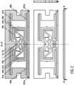
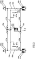
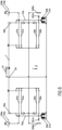
- the present invention presents an electromagnetically compensating beam balance which is Figure 1 is initially presented as a rigid body mechanism.
- the focus is on the design of the mechanism as a flexible mechanism, which can preferably be manufactured monolithically, i.e. from a semi-finished product.
- the beam balance can have weighing pans, each arranged on one side of the transmission lever (1).
- a distinction can be made between fixed weighing pans (110a,b) and gimbal-mounted, hanging weighing pans (111a,b).
- the weighing pans are each mechanically attached to the so-called load bearing element (70a,b), which is guided relative to a frame (15) by means of a lever mechanism.
- This lever mechanism consists of four joints and four links and is referred to as a parallel crank in gear technology.
- the force flow that comes from the weight of the weights (100a,b or 101a,b) on the scale pans (110a,b or 111a,b) is transmitted to the transmission lever (1) on each side by the coupling element (50a,b). If the lever lengths to the lever joint (10) are the same, the moments of weights with the same mass should compensate each other exactly. If the weights have a difference in mass, the static equilibrium is disturbed.
- the additional forces mentioned can be generated, for example, by an electromagnetic actuator. Its main components are a magnet system (21a,b,c) fixed to the frame and a coil (20a,b,c) that moves with it. If an electric current flows through a coil of one of these magnet systems, a force proportional to the current is generated.
- the size of the required current or the additional force can be defined using a closed control loop.
- An elementary component of such a control loop is a position sensor (200a,b and 201a,b), with which the deflection of the transmission lever (1) relative to the frame (15) can be determined.
- the Position sensor (200a,b and 201a,b) consists of two parts, a frame-fixed unit (200a,b) and a moving unit (201a,b). This is often designed as an optical sensor.
- the actuator consisting of 20c and 21c is an option that is only available in Figure 1 However, all embodiments shown in the following figures can also be supplemented with this actuator variant. This also applies to the adjustment weights described below.
- the beam balance has a lever adjustment weight (300). This is positioned on the lever joint (10) in such a way that the center of gravity of the rotationally moved transmission lever (1) can be adjusted in the vertical direction close to the center of the lever joint (10). The horizontal center of gravity of the transmission lever (1) should remain as unaffected as possible.
- this adjustment weight (300) By using and additionally fine-tuning this adjustment weight (300), the sensitivity to inclination, i.e. the influence of ground inclinations on the measured value, is minimized.
- a preferred embodiment provides for the vertical joint distance between the lever joint (10) and the outer lever joints (51a,b) to be designed such that the initial torsional stiffness of the compliant mechanism is compensated.
- the lever mechanism presented here can be used to separate the functions of guidance and transmission.
- the solid joints for power transmission are arranged vertically and are loaded by a tensile force.
- the joints that fulfill the guiding function as part of the parallel cranks and are loaded by horizontal forces are aligned horizontally. This means that the aforementioned sub-functions can be implemented with an optimized design of the lever mechanism.
- the outer (lateral) joints on the lever (51a,b) are preferably arranged at a defined vertical distance from the lever joint (10).
- the load supports (70a,b) can be stiffened by connecting them to other structural elements (not shown) and the topology of the transmission lever (1) can be optimized for high rigidity with minimal mass.
- the moving parts of the symmetrically arranged position sensors (201a,b) can be arranged with a large horizontal distance from the center of rotation, which contributes to further increasing the sensitivity of the scale.
- Figure 5 shows another embodiment in which a planar frame connection of all components can be realized. This is achieved by relocating the transmission lever (1) below the entire lever structure.
- the linear guide properties can be improved by means of a so-called double parallel crank.
- a perfect linear movement of the Load bearing and the components firmly connected to it coil (20a,b), position sensor (201a,b) and weighing pan (110a,b).
- planar, flexible lever mechanism in no way exclude its design in the third spatial direction.
- the parallel cranks of the quasi-linear guide can be located symmetrically outside the center plane of the lever mechanism.
- the coupling band does not necessarily have to be connected to the other links via two joints. It is sufficient to introduce a flexible element with distributed flexibility.
- the representation as an upper-pan weighing system does not exclude simultaneous or exclusive use as a lower-pan weighing system.
- the position, number and wiring of the components of the electromagnetically compensating beam balance can be determined analogously to the DE 10 2016 106 695 B4 described embodiments can be varied.
- the two parallel cranks and/or the two parallel links (60a,b, 61a,b) can be movable separately and independently of one another in the embodiments shown above.
Landscapes
- Physics & Mathematics (AREA)
- Electromagnetism (AREA)
- General Physics & Mathematics (AREA)
- Measurement Of Force In General (AREA)
Claims (13)
- Balance à fléau avec compensation électromagnétique, comprenant un levier de transmission (1) à deux bras, monté en rotation, dont chaque bras de levier est couplé à un support de charge (70a,b) qui lui est associé, et qui présente au moins sur un côté un actionneur (20a,b ; 21a,b) intégré dans une boucle d'asservissement fermée, dans laquelle chaque support de charge (70a,b) sera ou est guidé de manière linéaire dans la direction verticale au moyen d'un mécanisme de levier,
caractérisée en ce que le mécanisme de levier est réalisé respectivement sous la forme d'une manivelle parallèle composée d'une bielle parallèle supérieure (61a) reliée de manière solidaire du bâti et de manière articulée par l'intermédiaire d'un élément de couplage (50a,b), d'une bielle parallèle inférieure (60a), du support de charge (70a) et d'une bielle parallèle supérieure (61b), d'une bielle parallèle inférieure (60b) et du support de charge (70b). - Balance à fléau avec compensation électromagnétique selon la revendication 1, caractérisée en ce que le levier de transmission (1) présente un actionneur horizontal (20c, 21c) au-dessous d'une articulation de levier (10).
- Balance à fléau avec compensation électromagnétique selon l'une quelconque des revendications 1 ou 2, caractérisée en ce qu'elle présente un poids d'ajustage (300) pour le levier de transmission (1) dont le centre de gravité peut être ajusté dans la direction verticale proche du centre d'une articulation de levier (10).
- Balance à fléau avec compensation électromagnétique selon l'une quelconque des revendications 1 à 3, caractérisée en ce qu'elle présente respectivement un poids d'ajustage (360a,b et 361a,b) sur la bielle parallèle supérieure et/ou inférieure (60a,b et 61a,b).
- Balance à fléau avec compensation électromagnétique selon l'une quelconque des revendications 1 à 4, caractérisée en ce que pour compenser la rigidité à la torsion du mécanisme de lever, les deux bras du levier de transmission (1) sont couplés par l'intermédiaire d'articulations de levier extérieures (51a,b) à l'élément de couplage respectif (50a,b) à distance verticale d'une articulation de levier (10).
- Balance à fléau avec compensation électromagnétique selon l'une quelconque des revendications 1 à 5, caractérisée en ce que des plateaux (111a,b) montés rigidement (110a,b) et/ou suspendus à la Cardan aux supports de charge (70a,b) sont couplés mécaniquement.
- Balance à fléau avec compensation électromagnétique selon l'une quelconque des revendications précédentes, caractérisée en ce que chacune des boucles d'asservissement fermées comprend respectivement un actionneur électromagnétique composé d'un système magnétique (21a,b,) solidaire du bâti et d'un agencement de bobine associé (20a,b,c), et pour déterminer l'excursion du levier de transmission (1) par rapport au bâti (15), un capteur de position composé d'une unité (200a,b,c) solidaire du bâti et d'une unité associée (201a,b,c).
- Balance à fléau avec compensation électromagnétique selon l'une quelconque des revendications précédentes, caractérisée en ce que les mécanismes de levier bilatéraux sont réalisés sous la forme d'une structure globale plane, monolithique.
- Balance à fléau avec compensation électromagnétique selon l'une quelconque des revendications précédentes, caractérisée en ce que les manivelles parallèles sont couplées et/ou positionnées de manière optimisée au niveau du levier de transmission (1) selon chaque application spécifique.
- Balance à fléau avec compensation électromagnétique selon la revendication 8, caractérisée en ce que les manivelles parallèles présentent respectivement deux bielles parallèles inférieure et supérieure disposées en parallèle l'une à l'autre.
- Balance à fléau avec compensation électromagnétique selon l'une quelconque des revendications 7 à 10, caractérisée en ce que le capteur de position est réalisé sous la forme d'un capteur optique.
- Balance à fléau avec compensation électromagnétique selon l'une quelconque des revendications 5 à 11, caractérisée en ce que l'espacement vertical entre l'articulation de levier (10) et les articulations de levier extérieures (51a,b) est configuré de façon à compenser une rigidité à la torsion initiale du mécanisme de levier.
- Balance à fléau avec compensation électromagnétique selon l'une quelconque des revendications 2 à 12, caractérisée en ce que l'articulation de levier (10) et/ou les articulations de levier extérieures (51a,b) sont réalisées sous la forme d'articulations à corps solide.
Applications Claiming Priority (1)
| Application Number | Priority Date | Filing Date | Title |
|---|---|---|---|
| DE102021118060.0A DE102021118060A1 (de) | 2021-07-13 | 2021-07-13 | Elektromagnetisch kompensierende Balkenwaage |
Publications (2)
| Publication Number | Publication Date |
|---|---|
| EP4119908A1 EP4119908A1 (fr) | 2023-01-18 |
| EP4119908B1 true EP4119908B1 (fr) | 2025-02-12 |
Family
ID=82403349
Family Applications (1)
| Application Number | Title | Priority Date | Filing Date |
|---|---|---|---|
| EP22183790.9A Active EP4119908B1 (fr) | 2021-07-13 | 2022-07-08 | Balance à fléau avec compensation électromagnétique |
Country Status (2)
| Country | Link |
|---|---|
| EP (1) | EP4119908B1 (fr) |
| DE (1) | DE102021118060A1 (fr) |
Families Citing this family (1)
| Publication number | Priority date | Publication date | Assignee | Title |
|---|---|---|---|---|
| CN116242577B (zh) * | 2023-05-06 | 2023-07-07 | 中国空气动力研究与发展中心低速空气动力研究所 | 一种风洞集群特种天平及集群测量的风洞系统 |
Citations (1)
| Publication number | Priority date | Publication date | Assignee | Title |
|---|---|---|---|---|
| DE102022101797A1 (de) * | 2022-01-26 | 2023-07-27 | Technische Universität Ilmenau, Körperschaft des öffentlichen Rechts | Vorrichtung zur Justierung der messtechnischen Eigenschaften von Mechanismen für die Kraftmess- und Wägetechnik |
Family Cites Families (2)
| Publication number | Priority date | Publication date | Assignee | Title |
|---|---|---|---|---|
| EP2610596B2 (fr) * | 2011-12-30 | 2022-03-30 | WIPOTEC GmbH | Elément de pont pour une balance |
| DE102016106695B4 (de) | 2016-04-12 | 2018-11-08 | Sartorius Lab Instruments Gmbh & Co. Kg | Elektromagnetisch kompensierende Balkenwaage, Verfahren zu deren Kalibrierung und Verfahren zur Bestimmung eines Testgewichts |
-
2021
- 2021-07-13 DE DE102021118060.0A patent/DE102021118060A1/de not_active Ceased
-
2022
- 2022-07-08 EP EP22183790.9A patent/EP4119908B1/fr active Active
Patent Citations (1)
| Publication number | Priority date | Publication date | Assignee | Title |
|---|---|---|---|---|
| DE102022101797A1 (de) * | 2022-01-26 | 2023-07-27 | Technische Universität Ilmenau, Körperschaft des öffentlichen Rechts | Vorrichtung zur Justierung der messtechnischen Eigenschaften von Mechanismen für die Kraftmess- und Wägetechnik |
Also Published As
| Publication number | Publication date |
|---|---|
| DE102021118060A1 (de) | 2023-01-19 |
| EP4119908A1 (fr) | 2023-01-18 |
Similar Documents
| Publication | Publication Date | Title |
|---|---|---|
| EP2032954B1 (fr) | Couplage mécanique pour une masse d'étalonnage dans une balance électronique | |
| EP2153185B1 (fr) | Guidage parallèle réglable pour instruments de mesure gravimétriques compacts | |
| DE69703871T2 (de) | Flexibles planares Gelenk mit einzelnen, monolithischen Modulen | |
| DE10344178B4 (de) | Halte- und Positioniervorrichtung für ein optisches Element | |
| WO2010066873A1 (fr) | Compensation de la gravitation pour les éléments optiques dans les installations d'éclairage par projection | |
| DE102016106048A1 (de) | Wägeaufnehmer | |
| CH641561A5 (de) | Kraftausgleichvorrichtung zur verwendung derselben in einem beschleunigungsmesser. | |
| EP2690415A1 (fr) | Dispositif de mesure de force avec poids de déplacement | |
| EP4445106B1 (fr) | Dispositif de pesage et son procédé de fonctionnement | |
| DE10054847C2 (de) | Wägeaufnehmer mit Justiergewicht | |
| EP2533024A1 (fr) | Dispositif de transmission de force avec un poids de calibrage couplable | |
| EP4119908B1 (fr) | Balance à fléau avec compensation électromagnétique | |
| DE102011000554A1 (de) | Wägezelle sowie Verfahren zum Justieren einer Wägezelle | |
| DE10326699B3 (de) | Kompaktes Wägesystem | |
| EP0555876A1 (fr) | Dispositif pour mesurer la force, en particulier une balance, avec aiguille électromagnétique | |
| EP2610596B2 (fr) | Elément de pont pour une balance | |
| EP2434264A1 (fr) | Dispositif de transmission d'énergie avec un poids de calibrage pouvant être couplé | |
| EP3667265A1 (fr) | Dispositif d'étalonnage de poids pour un appareil de mesure gravimétrique | |
| DE102021132093B3 (de) | Wägevorrichtung und Verfahren zu deren Betrieb | |
| EP2434265B1 (fr) | Dispositif de pesage avec découplage thermique | |
| EP1657577B1 (fr) | Support pivotant permettant un réglage de haute précision de la position angulaire d'un objet | |
| EP2610595B1 (fr) | Pont de pesage | |
| DE102022101797A1 (de) | Vorrichtung zur Justierung der messtechnischen Eigenschaften von Mechanismen für die Kraftmess- und Wägetechnik | |
| DE102025100938B3 (de) | Wägesystem mit Astasierungshebel | |
| DE2830071C3 (de) | Wagebrücke mit Abstützung auf Meßdosen |
Legal Events
| Date | Code | Title | Description |
|---|---|---|---|
| PUAI | Public reference made under article 153(3) epc to a published international application that has entered the european phase |
Free format text: ORIGINAL CODE: 0009012 |
|
| STAA | Information on the status of an ep patent application or granted ep patent |
Free format text: STATUS: THE APPLICATION HAS BEEN PUBLISHED |
|
| AK | Designated contracting states |
Kind code of ref document: A1 Designated state(s): AL AT BE BG CH CY CZ DE DK EE ES FI FR GB GR HR HU IE IS IT LI LT LU LV MC MK MT NL NO PL PT RO RS SE SI SK SM TR |
|
| STAA | Information on the status of an ep patent application or granted ep patent |
Free format text: STATUS: REQUEST FOR EXAMINATION WAS MADE |
|
| 17P | Request for examination filed |
Effective date: 20230717 |
|
| RBV | Designated contracting states (corrected) |
Designated state(s): AL AT BE BG CH CY CZ DE DK EE ES FI FR GB GR HR HU IE IS IT LI LT LU LV MC MK MT NL NO PL PT RO RS SE SI SK SM TR |
|
| STAA | Information on the status of an ep patent application or granted ep patent |
Free format text: STATUS: EXAMINATION IS IN PROGRESS |
|
| 17Q | First examination report despatched |
Effective date: 20240423 |
|
| GRAP | Despatch of communication of intention to grant a patent |
Free format text: ORIGINAL CODE: EPIDOSNIGR1 |
|
| STAA | Information on the status of an ep patent application or granted ep patent |
Free format text: STATUS: GRANT OF PATENT IS INTENDED |
|
| INTG | Intention to grant announced |
Effective date: 20240916 |
|
| GRAS | Grant fee paid |
Free format text: ORIGINAL CODE: EPIDOSNIGR3 |
|
| GRAA | (expected) grant |
Free format text: ORIGINAL CODE: 0009210 |
|
| STAA | Information on the status of an ep patent application or granted ep patent |
Free format text: STATUS: THE PATENT HAS BEEN GRANTED |
|
| AK | Designated contracting states |
Kind code of ref document: B1 Designated state(s): AL AT BE BG CH CY CZ DE DK EE ES FI FR GB GR HR HU IE IS IT LI LT LU LV MC MK MT NL NO PL PT RO RS SE SI SK SM TR |
|
| REG | Reference to a national code |
Ref country code: GB Ref legal event code: FG4D Free format text: NOT ENGLISH |
|
| REG | Reference to a national code |
Ref country code: CH Ref legal event code: EP |
|
| P01 | Opt-out of the competence of the unified patent court (upc) registered |
Free format text: CASE NUMBER: APP_3325/2025 Effective date: 20250123 |
|
| REG | Reference to a national code |
Ref country code: DE Ref legal event code: R096 Ref document number: 502022002852 Country of ref document: DE |
|
| REG | Reference to a national code |
Ref country code: IE Ref legal event code: FG4D Free format text: LANGUAGE OF EP DOCUMENT: GERMAN |
|
| REG | Reference to a national code |
Ref country code: NL Ref legal event code: MP Effective date: 20250212 |
|
| PG25 | Lapsed in a contracting state [announced via postgrant information from national office to epo] |
Ref country code: RS Free format text: LAPSE BECAUSE OF FAILURE TO SUBMIT A TRANSLATION OF THE DESCRIPTION OR TO PAY THE FEE WITHIN THE PRESCRIBED TIME-LIMIT Effective date: 20250512 |
|
| PG25 | Lapsed in a contracting state [announced via postgrant information from national office to epo] |
Ref country code: FI Free format text: LAPSE BECAUSE OF FAILURE TO SUBMIT A TRANSLATION OF THE DESCRIPTION OR TO PAY THE FEE WITHIN THE PRESCRIBED TIME-LIMIT Effective date: 20250212 |
|
| PG25 | Lapsed in a contracting state [announced via postgrant information from national office to epo] |
Ref country code: PL Free format text: LAPSE BECAUSE OF FAILURE TO SUBMIT A TRANSLATION OF THE DESCRIPTION OR TO PAY THE FEE WITHIN THE PRESCRIBED TIME-LIMIT Effective date: 20250212 |
|
| PG25 | Lapsed in a contracting state [announced via postgrant information from national office to epo] |
Ref country code: ES Free format text: LAPSE BECAUSE OF FAILURE TO SUBMIT A TRANSLATION OF THE DESCRIPTION OR TO PAY THE FEE WITHIN THE PRESCRIBED TIME-LIMIT Effective date: 20250212 |
|
| REG | Reference to a national code |
Ref country code: LT Ref legal event code: MG9D |
|
| PG25 | Lapsed in a contracting state [announced via postgrant information from national office to epo] |
Ref country code: NO Free format text: LAPSE BECAUSE OF FAILURE TO SUBMIT A TRANSLATION OF THE DESCRIPTION OR TO PAY THE FEE WITHIN THE PRESCRIBED TIME-LIMIT Effective date: 20250512 Ref country code: IS Free format text: LAPSE BECAUSE OF FAILURE TO SUBMIT A TRANSLATION OF THE DESCRIPTION OR TO PAY THE FEE WITHIN THE PRESCRIBED TIME-LIMIT Effective date: 20250612 |
|
| PG25 | Lapsed in a contracting state [announced via postgrant information from national office to epo] |
Ref country code: NL Free format text: LAPSE BECAUSE OF FAILURE TO SUBMIT A TRANSLATION OF THE DESCRIPTION OR TO PAY THE FEE WITHIN THE PRESCRIBED TIME-LIMIT Effective date: 20250212 |
|
| PG25 | Lapsed in a contracting state [announced via postgrant information from national office to epo] |
Ref country code: HR Free format text: LAPSE BECAUSE OF FAILURE TO SUBMIT A TRANSLATION OF THE DESCRIPTION OR TO PAY THE FEE WITHIN THE PRESCRIBED TIME-LIMIT Effective date: 20250212 |
|
| PG25 | Lapsed in a contracting state [announced via postgrant information from national office to epo] |
Ref country code: PT Free format text: LAPSE BECAUSE OF FAILURE TO SUBMIT A TRANSLATION OF THE DESCRIPTION OR TO PAY THE FEE WITHIN THE PRESCRIBED TIME-LIMIT Effective date: 20250612 Ref country code: LV Free format text: LAPSE BECAUSE OF FAILURE TO SUBMIT A TRANSLATION OF THE DESCRIPTION OR TO PAY THE FEE WITHIN THE PRESCRIBED TIME-LIMIT Effective date: 20250212 |
|
| PG25 | Lapsed in a contracting state [announced via postgrant information from national office to epo] |
Ref country code: GR Free format text: LAPSE BECAUSE OF FAILURE TO SUBMIT A TRANSLATION OF THE DESCRIPTION OR TO PAY THE FEE WITHIN THE PRESCRIBED TIME-LIMIT Effective date: 20250513 Ref country code: BG Free format text: LAPSE BECAUSE OF FAILURE TO SUBMIT A TRANSLATION OF THE DESCRIPTION OR TO PAY THE FEE WITHIN THE PRESCRIBED TIME-LIMIT Effective date: 20250212 |
|
| PG25 | Lapsed in a contracting state [announced via postgrant information from national office to epo] |
Ref country code: SE Free format text: LAPSE BECAUSE OF FAILURE TO SUBMIT A TRANSLATION OF THE DESCRIPTION OR TO PAY THE FEE WITHIN THE PRESCRIBED TIME-LIMIT Effective date: 20250212 |
|
| PG25 | Lapsed in a contracting state [announced via postgrant information from national office to epo] |
Ref country code: SM Free format text: LAPSE BECAUSE OF FAILURE TO SUBMIT A TRANSLATION OF THE DESCRIPTION OR TO PAY THE FEE WITHIN THE PRESCRIBED TIME-LIMIT Effective date: 20250212 |
|
| PG25 | Lapsed in a contracting state [announced via postgrant information from national office to epo] |
Ref country code: DK Free format text: LAPSE BECAUSE OF FAILURE TO SUBMIT A TRANSLATION OF THE DESCRIPTION OR TO PAY THE FEE WITHIN THE PRESCRIBED TIME-LIMIT Effective date: 20250212 |
|
| PGFP | Annual fee paid to national office [announced via postgrant information from national office to epo] |
Ref country code: DE Payment date: 20250731 Year of fee payment: 4 |
|
| PG25 | Lapsed in a contracting state [announced via postgrant information from national office to epo] |
Ref country code: IT Free format text: LAPSE BECAUSE OF FAILURE TO SUBMIT A TRANSLATION OF THE DESCRIPTION OR TO PAY THE FEE WITHIN THE PRESCRIBED TIME-LIMIT Effective date: 20250212 |
|
| PGFP | Annual fee paid to national office [announced via postgrant information from national office to epo] |
Ref country code: AT Payment date: 20251020 Year of fee payment: 4 Ref country code: FR Payment date: 20250723 Year of fee payment: 4 |
|
| PGFP | Annual fee paid to national office [announced via postgrant information from national office to epo] |
Ref country code: CH Payment date: 20250801 Year of fee payment: 4 |
|
| PG25 | Lapsed in a contracting state [announced via postgrant information from national office to epo] |
Ref country code: CZ Free format text: LAPSE BECAUSE OF FAILURE TO SUBMIT A TRANSLATION OF THE DESCRIPTION OR TO PAY THE FEE WITHIN THE PRESCRIBED TIME-LIMIT Effective date: 20250212 Ref country code: EE Free format text: LAPSE BECAUSE OF FAILURE TO SUBMIT A TRANSLATION OF THE DESCRIPTION OR TO PAY THE FEE WITHIN THE PRESCRIBED TIME-LIMIT Effective date: 20250212 |
|
| PG25 | Lapsed in a contracting state [announced via postgrant information from national office to epo] |
Ref country code: RO Free format text: LAPSE BECAUSE OF FAILURE TO SUBMIT A TRANSLATION OF THE DESCRIPTION OR TO PAY THE FEE WITHIN THE PRESCRIBED TIME-LIMIT Effective date: 20250212 |
|
| PG25 | Lapsed in a contracting state [announced via postgrant information from national office to epo] |
Ref country code: SK Free format text: LAPSE BECAUSE OF FAILURE TO SUBMIT A TRANSLATION OF THE DESCRIPTION OR TO PAY THE FEE WITHIN THE PRESCRIBED TIME-LIMIT Effective date: 20250212 |
|
| REG | Reference to a national code |
Ref country code: DE Ref legal event code: R097 Ref document number: 502022002852 Country of ref document: DE |
|
| PLBE | No opposition filed within time limit |
Free format text: ORIGINAL CODE: 0009261 |
|
| STAA | Information on the status of an ep patent application or granted ep patent |
Free format text: STATUS: NO OPPOSITION FILED WITHIN TIME LIMIT |
|
| 26N | No opposition filed |
Effective date: 20251113 |
|
| PG25 | Lapsed in a contracting state [announced via postgrant information from national office to epo] |
Ref country code: LU Free format text: LAPSE BECAUSE OF NON-PAYMENT OF DUE FEES Effective date: 20250708 |
|
| REG | Reference to a national code |
Ref country code: BE Ref legal event code: MM Effective date: 20250731 |
|
| PG25 | Lapsed in a contracting state [announced via postgrant information from national office to epo] |
Ref country code: BE Free format text: LAPSE BECAUSE OF NON-PAYMENT OF DUE FEES Effective date: 20250731 |