EP4119973A1 - Positionnement dans un système de communication mobile - Google Patents
Positionnement dans un système de communication mobile Download PDFInfo
- Publication number
- EP4119973A1 EP4119973A1 EP21185255.3A EP21185255A EP4119973A1 EP 4119973 A1 EP4119973 A1 EP 4119973A1 EP 21185255 A EP21185255 A EP 21185255A EP 4119973 A1 EP4119973 A1 EP 4119973A1
- Authority
- EP
- European Patent Office
- Prior art keywords
- nodes
- positioning signals
- pairs
- positioning
- communication system
- Prior art date
- Legal status (The legal status is an assumption and is not a legal conclusion. Google has not performed a legal analysis and makes no representation as to the accuracy of the status listed.)
- Pending
Links
Images



Classifications
-
- H—ELECTRICITY
- H04—ELECTRIC COMMUNICATION TECHNIQUE
- H04W—WIRELESS COMMUNICATION NETWORKS
- H04W4/00—Services specially adapted for wireless communication networks; Facilities therefor
- H04W4/02—Services making use of location information
- H04W4/025—Services making use of location information using location based information parameters
-
- G—PHYSICS
- G01—MEASURING; TESTING
- G01S—RADIO DIRECTION-FINDING; RADIO NAVIGATION; DETERMINING DISTANCE OR VELOCITY BY USE OF RADIO WAVES; LOCATING OR PRESENCE-DETECTING BY USE OF THE REFLECTION OR RERADIATION OF RADIO WAVES; ANALOGOUS ARRANGEMENTS USING OTHER WAVES
- G01S5/00—Position-fixing by co-ordinating two or more direction or position line determinations; Position-fixing by co-ordinating two or more distance determinations
- G01S5/02—Position-fixing by co-ordinating two or more direction or position line determinations; Position-fixing by co-ordinating two or more distance determinations using radio waves
- G01S5/0205—Details
-
- G—PHYSICS
- G01—MEASURING; TESTING
- G01S—RADIO DIRECTION-FINDING; RADIO NAVIGATION; DETERMINING DISTANCE OR VELOCITY BY USE OF RADIO WAVES; LOCATING OR PRESENCE-DETECTING BY USE OF THE REFLECTION OR RERADIATION OF RADIO WAVES; ANALOGOUS ARRANGEMENTS USING OTHER WAVES
- G01S5/00—Position-fixing by co-ordinating two or more direction or position line determinations; Position-fixing by co-ordinating two or more distance determinations
- G01S5/02—Position-fixing by co-ordinating two or more direction or position line determinations; Position-fixing by co-ordinating two or more distance determinations using radio waves
- G01S5/0284—Relative positioning
- G01S5/0289—Relative positioning of multiple transceivers, e.g. in ad hoc networks
-
- G—PHYSICS
- G01—MEASURING; TESTING
- G01S—RADIO DIRECTION-FINDING; RADIO NAVIGATION; DETERMINING DISTANCE OR VELOCITY BY USE OF RADIO WAVES; LOCATING OR PRESENCE-DETECTING BY USE OF THE REFLECTION OR RERADIATION OF RADIO WAVES; ANALOGOUS ARRANGEMENTS USING OTHER WAVES
- G01S1/00—Beacons or beacon systems transmitting signals having a characteristic or characteristics capable of being detected by non-directional receivers and defining directions, positions, or position lines fixed relatively to the beacon transmitters; Receivers co-operating therewith
- G01S1/02—Beacons or beacon systems transmitting signals having a characteristic or characteristics capable of being detected by non-directional receivers and defining directions, positions, or position lines fixed relatively to the beacon transmitters; Receivers co-operating therewith using radio waves
- G01S1/04—Details
- G01S1/042—Transmitters
-
- H—ELECTRICITY
- H04—ELECTRIC COMMUNICATION TECHNIQUE
- H04W—WIRELESS COMMUNICATION NETWORKS
- H04W4/00—Services specially adapted for wireless communication networks; Facilities therefor
- H04W4/02—Services making use of location information
- H04W4/023—Services making use of location information using mutual or relative location information between multiple location based services [LBS] targets or of distance thresholds
-
- H—ELECTRICITY
- H04—ELECTRIC COMMUNICATION TECHNIQUE
- H04W—WIRELESS COMMUNICATION NETWORKS
- H04W64/00—Locating users or terminals or network equipment for network management purposes, e.g. mobility management
- H04W64/003—Locating users or terminals or network equipment for network management purposes, e.g. mobility management locating network equipment
-
- H—ELECTRICITY
- H04—ELECTRIC COMMUNICATION TECHNIQUE
- H04W—WIRELESS COMMUNICATION NETWORKS
- H04W64/00—Locating users or terminals or network equipment for network management purposes, e.g. mobility management
- H04W64/006—Locating users or terminals or network equipment for network management purposes, e.g. mobility management with additional information processing, e.g. for direction or speed determination
Definitions
- the present specification relates to positioning in mobile communication systems.
- positioning signals such as positioning reference signals
- this specification describes an apparatus comprising means for performing: receiving, at a user device, positioning signals from each of a plurality of nodes of a mobile communication system, wherein the positioning signals comprise first positioning signals (e.g. first positioning reference signals) received from each of one or more fixed nodes of the mobile communication system and second positioning signals (e.g. second positioning reference signals) received from each of one or more mobile nodes of the mobile communication system; determining relative angles of arrival of positioning signals between a first plurality of pairs of said nodes; determining a collinearity indication for each of the pairs of nodes of the first plurality, wherein each collinearity indication is based on the respective determined relative angles of arrival of said positioning signals; and selecting (e.g.
- the collinearity indication may be based on a binary threshold (e.g. above/below a threshold), may be based on multiple threshold, or may be a sliding scale).
- Each relative angle of arrival may comprise an angle of arrival difference between: first positioning signals received from different ones of the plurality of fixed nodes; second positioning signals received from different ones of the plurality of mobile nodes; or first positioning signals received from one of the plurality of fixed nodes and second positioning signals received from one of the plurality of mobile nodes.
- Selecting at least some of the plurality of pairs of nodes may comprise selecting pairs of nodes having a determined collinearity below a threshold level.
- selecting at least some of the plurality of pairs of nodes may be based, at least in part, on received signal strength and/or position confidence. Note that position confidence level may be relevant only for mobile nodes (since the position of fixed nodes maybe known precisely, i.e. with high confidence).
- Some example embodiments further comprise means for performing: receiving assistance data comprising one or more of: a coarse position estimate of the user device; information identifying potential values of collinearity (e.g. geometric dilution of precision) that are above a threshold level (e.g. above a tolerable level); information identifying nodes of the mobile communication system from which positioning reference signals should be obtained/measured; information identifying pairs of nodes of the mobile communication system for which relative angles of arrival should be determined; and position confidence information (e.g. position variance) for some or all of the mobile nodes of the mobile communication system.
- Some or all of the said assistance data may be received from the network (e.g. from an LMF).
- some or all of said mobile nodes are other user devices of the mobile communication system.
- some or all of said fixed nodes may be transmission reception points or base stations of said mobile communication system.
- said second positioning signals are provided from said mobile nodes to said user device using a direct link (e.g. sidelinks) between mobile nodes.
- a direct link e.g. sidelinks
- Some example embodiments further comprise means for performing: estimating or refining a position of the user device based on some or all of the selected pairs of nodes.
- Some example embodiments further comprise means for performing: causing a first position estimate to be generated based on first positioning signals received from selected pairs of fixed nodes; and causing a second, refined, position estimate to be generated based on positioning signals from some or all of the selected pairs of nodes.
- the second position estimate may be based on second positioning signals received from selected pairs of mobile nodes.
- Some example embodiments further comprise means for performing: causing a third, further refined, position estimate, to be generated using further nodes of the plurality.
- the means may comprise: at least one processor; and at least one memory including computer program code, the at least one memory and computer program code configured to, with the at least one processor, cause the performance of the apparatus.
- this specification describes a method comprising: receiving, at a user device, positioning signals from each of a plurality of nodes of a mobile communication system, wherein the positioning signals comprise first positioning signals received from each of one or more fixed nodes of the mobile communication system and second positioning signals received from each of one or more mobile nodes of the mobile communication system; determining relative angles of arrival of positioning signals between a first plurality of pairs of said nodes; determining a collinearity indication for each of the pairs of nodes of the first plurality, wherein each collinearity indication is based on the respective determined relative angles of arrival of said positioning signals; and selecting at least some of the plurality of pairs of nodes for use in positioning refinement, wherein the selecting is based, at least in part, on the determined collinearity.
- Selecting at least some of the plurality of pairs of nodes may comprise selecting pairs of nodes having a determined collinearity below a threshold level.
- Selecting at least some of the plurality of pairs of nodes may be based, at least in part, on received signal strength and/or position confidence.
- the method may further comprise receiving assistance data comprising features such as one or more of: a coarse position estimate of the user device; information identifying potential values of collinearity that are above a threshold level; information identifying nodes of the mobile communication system from which positioning reference signals should be obtained; information identifying pairs of nodes of the mobile communication system for which relative angles of arrival should be determined; and position confidence information for some or all of the mobile nodes of the mobile communication system.
- assistance data comprising features such as one or more of: a coarse position estimate of the user device; information identifying potential values of collinearity that are above a threshold level; information identifying nodes of the mobile communication system from which positioning reference signals should be obtained; information identifying pairs of nodes of the mobile communication system for which relative angles of arrival should be determined; and position confidence information for some or all of the mobile nodes of the mobile communication system.
- the second positioning signals may be provided from said mobile nodes to said user device using a direct link (e.g. sidelinks) between mobile nodes.
- a direct link e.g. sidelinks
- the method may further comprise estimating or refining a position of the user device based on some or all of the selected pairs of nodes.
- the method may further comprise: causing a first position estimate to be generated based on first positioning signals received from selected pairs of fixed nodes; and causing a second, refined, position estimate to be generated based on positioning signals from some or all of the selected pairs of nodes.
- the method may further comprise causing a third, further refined, position estimate, to be generated using further nodes of the plurality.
- this specification describes an apparatus configured to perform any (at least) any method as described with reference to the second aspect.
- this specification describes computer-readable instructions which, when executed by a computing apparatus, cause the computing apparatus to perform (at least) any method as described with reference to the second aspect.
- this specification describes a computer-readable medium (such as a non-transitory computer-readable medium) comprising program instructions stored thereon for performing (at least) any method as described with reference to the second aspect.
- this specification describes an apparatus comprising: at least one processor; and at least one memory including computer program code which, when executed by the at least one processor, causes the apparatus to perform (at least) any method as described with reference to the second aspect.
- this specification describes a computer program comprising instructions for causing an apparatus to perform at least the following: receiving, at a user device, positioning signals from each of a plurality of nodes of a mobile communication system, wherein the positioning signals comprise first positioning signals received from each of one or more fixed nodes of the mobile communication system and second positioning signals received from each of one or more mobile nodes of the mobile communication system; determining relative angles of arrival of positioning signals between a first plurality of pairs of said nodes; determining a collinearity indication for each of the pairs of nodes of the first plurality, wherein each collinearity indication is based on the respective determined relative angles of arrival of said positioning signals; and selecting at least some of the plurality of pairs of nodes for use in positioning refinement, wherein the selecting is based, at least in part, on the determined collinearity.
- this specification describes an apparatus comprising: a receiver (or some other means) for receiving, at a user device, positioning signals from each of a plurality of nodes of a mobile communication system, wherein the positioning signals comprise first positioning signals (e.g. first positioning reference signals) received from each of one or more fixed nodes of the mobile communication system and second positioning signals (e.g.
- second positioning reference signals received from each of one or more mobile nodes of the mobile communication system; and a processor (or some other means) for: determining relative angles of arrival of positioning signals between a first plurality of pairs of said nodes; determining a collinearity indication for each of the pairs of nodes of the first plurality, wherein each collinearity indication is based on the respective determined relative angles of arrival of said positioning signals; and selecting (e.g. by adding and/or removing pairs to/from a candidate list) at least some of the plurality of pairs of nodes for use in determining or refining a position of the user device, wherein the selecting is based, at least in part, on the determined collinearity (e.g. relative to a threshold).
- the determined collinearity e.g. relative to a threshold
- FIG. 1 is a block diagram of a system, indicated generally by the reference numeral 10, in accordance with an example embodiment.
- the system 10 comprises a transmission and reception point or base station (TRP), a first user device 14, a second user device 16 and a third user device 18.
- TRP transmission and reception point or base station
- the first user device 14 receives positioning reference signals (PRS) from the TRP 12 (and may receive PRS information from other TRPs). Based on the received positioning reference signals and the known TRP location, the user device 14 is able to estimate its position (thereby performing UE-based downlink positioning).
- PRS positioning reference signals
- V2X Vehicle-to-everything
- the first user device 14 may also receive positioning information from the second and third user devices 16 and 18 (e.g. using sidelinks, or some other direct link, as discussed further below).
- FIG. 2 is a flow chart showing a method, indicated generally by the reference numeral 20, in accordance with an example embodiment.
- the method 20 may be implemented using the system 10.
- the method 20 starts at operation 22, where positioning reference signals (e.g. PRS) are received at the first user device 14 from the TRP 12, as discussed above.
- positioning reference signals e.g. PRS
- SL sidelink positioning reference signals
- sidelink-aided positioning is performed (e.g. at the first user device 14) to determine an estimate of the position of the first user device 14.
- the method 20 enables UE-based downlink positioning that is enhanced with sidelink (SL) assistance (i.e. SL-aided positioning).
- SL sidelink
- Sidelink-aided positioning involves the use of device-to-device messaging transmitted on the so-called sidelink (SL), i.e., a direct link between user devices.
- Sidelink messages can be exploited to enhance the positioning process of the user device, for example, they can be used as additional reference signals measured by the user device to yield higher location estimation accuracy or to replace reference signals transmitted by fixed TRP network entities in the event that those reference signals are received at the relevant user device (e.g. the first user device 14) with very low signal power or quality.
- the second and third user devices 16 and 18 that are assisting the positioning of the first user 14 device by transmitting reference signals in the sidelink are sometimes referred to below herein as supportive user devices (S-UEs).
- the first user device 14 is sometimes referred to herein as a target user device (T-UE).
- Sidelink communications may be relevant to the V2X use case referred to above, since many vehicles are using such functionality already. If sidelink channels already exist, then assisting the positioning performance with the use of sidelinks can be implemented with limited additional overhead. Sidelink communications, and sidelink-aided positioning, are useful in many other circumstances.
- sidelinks may also be useful for mitigating coverage errors in areas where the direct network coverage is not sufficient.
- the user devices/vehicles have only limited connection to the network towers (e.g. in mountain terrains where shadowing of the line of sight (LoS) signal to the base station is common).
- the positioning process that apply to positioning only (and not to communication), which relate to the relative geometry of the base stations with respect to the location of the target UE.
- GDOP geometric dilution of precision
- SL positioning is a promising technique that can allow increased levels of positioning accuracy, by leveraging the density of the multiple reference signals available for measurements at a user device (UE). Nevertheless, sidelink positioning comes with challenges; for example associated with the relative locations of the user devices, as discussed further below.
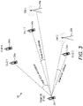
- FIG. 3 is a block diagram of a system, indicated generally by the reference numeral 30, in accordance with an example embodiment.
- the system 30 comprises a target user device (T-UE) 32, a first supportive user device (S-UE1) 34a, a second supportive user device (S-UE2) 34b, a third supportive user device (S-UE3) 34c, a fourth supportive user device (S-UE4) 34d, a first TRP or base station (TRP 1) 36a and a second TRP or base station (TRP 2) 36b.
- T-UE target user device
- S-UE1 first supportive user device
- S-UE2 second supportive user device
- S-UE3 third supportive user device
- S-UE4 supportive user device S-UE4
- TRP 1 TRP or base station
- TRP 2 TRP or base station
- the target user device 32 is able to conduct measurements on reference signals transmitted by the TRPs 36a and 36b and the S-UEs 34a to 34d. Simply adding all involved measured signals to the positioning process would result in relatively low accuracy, since the relative geometry of some combinations of TRPs and S-UEs are (approximately) collinear when viewed from the target user device 32.
- S-UE2 34b and TRP136a are approximately collinear when viewed from the T-UE 32, hence due to the GDOP referred to above, including both in positioning calculations will not result in higher positioning accuracy, but will increase computational overhead.
- the relative angle of arrival is considered.
- S-UE134a and S-UE4 34d have a relative angle of arrival at the target user device 32 which is relatively small, hence they should be assigned high collinearity.
- high collinearity is assigned at the T-UE 32 for the combination of TRPi 36a and S-UE2 34b.
- the accuracy of the location estimation at the target user device 32 may also depend on the confidence level on the location of the respective S-UEs. This is because the location of the target user device can be estimated by utilizing the location of the respective S-UEs and the corresponding measurements on the sidelink channels. As a result, information on the confidence (e.g. variance of the location estimate) on the location of S-UEs may be taken into account, as discussed further below.
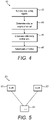
- FIG. 4 is a flow chart showing a method, indicated generally by the reference numeral 40, in accordance with an example embodiment.
- the method 40 may be implemented using the system 30.
- the method 40 starts at operation 42, where positioning reference signals are received at the target user device 32 from each of a plurality of nodes of a mobile communication system.
- the positioning reference signals include first positioning reference signals received from each of one or more fixed nodes of the mobile communication system (such as TRP136a and TRP2 36b) and second positioning reference signals received from each of one or more mobile nodes of the mobile communication system (such as first to fourth supportive user devices 32a-d). Some or all of said mobile nodes may be other user devices of the mobile communication system. Some or all of said fixed nodes may be transmission reception points or base stations of said mobile communication system.
- the second positioning reference signals may be provided from said mobile nodes to said user device using sidelinks.
- a collinearity indication for each of the pairs of nodes of the first plurality is determined, wherein each collinearity indication is based on the respective determined relative angles of arrival of said positioning reference signals.
- the collinearity indication may be a binary indication (e.g. whether the degree of collinearity is above or below a threshold). Alternatively, the collinearity indication may be based on multiple threshold, be based on a sliding scale, or be expressed in some other way.
- At operation 48 at least some of the plurality of pairs of nodes are selected for use in determining or refining a position of the target user device, wherein the selecting is based, at least in part, on the collinearity determined in operation 46 (e.g. whether the collinearity is above or below a threshold).
- the pairs of nodes may be selected in the operation 48 by adding and/or removing pairs of nodes from a candidate list, as discussed in detail below.
- FIG. 5 is a block diagram of a system, indicated generally by the reference numeral 50, in accordance with an example embodiment.
- the system 50 comprises a target user device 51, a first supportive user device 52 and a second supportive user device 53.
- the target user device 51 receives positioning reference signals (e.g. PRS) from different ones of the plurality of mobile nodes (in this case the first supportive user device 52 and the second supportive user device 53).
- PRS positioning reference signals
- a relative angle of arrival can therefore be determined based on difference between angles of arrival of the corresponding positioning reference signals with respect to a common orientation direction (e.g. the boresight direction of the target user device 51), as indicated in FIG. 5 .
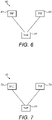
- FIG. 6 is a block diagram of a system, indicated generally by the reference numeral 60, in accordance with an example embodiment.
- the system 60 comprises the target user device 51, a first TRP 62 and a second TRP 63.
- the target user device 51 receives positioning reference signals (e.g. PRS) from different ones of the plurality of fixed nodes (in this case the first TRP 62 and the second TRP 63).
- PRS positioning reference signals
- a relative angle of arrival can therefore be determined based on an angle of arrival difference between the received positioning reference signals, as indicated in FIG. 6 .
- FIG. 7 is a block diagram of a system, indicated generally by the reference numeral 70, in accordance with an example embodiment.
- the system 70 comprises the target user device 51, a supportive user device 72 and a TRP 73.
- the target user device 51 receives positioning reference signals (e.g. PRS) from one of a plurality of mobile nodes (in this case the supportive user device 72) and one of a plurality of fixed nodes (in this case the TRP 73).
- PRS positioning reference signals
- a relative angle of arrival can therefore be determined based on an angle of arrival difference between the received positioning reference signals, as indicated in FIG. 7 .
- FIG. 8 is a block diagram of a system, indicated generally by the reference numeral 80, in accordance with an example embodiment.
- the system 80 comprises a computation module 81, a non-collinear selection module 82, a supportive user device (S-UE) selection module 83, an initial position estimation module 84, a first position refinement module 85 and a second position refinement module 86.
- the system 80 may be implemented at a user device (such as the target user devices 32 or 51 described above), although this is not essential to all example embodiments.
- the computation module 81 computes the relative angle of arrival between pairs of transmitters (e.g. pairs of supportive user devices, pairs of static TRPs or combinations of a supportive user device and a TRP, as described above with reference to FIGS. 5 to 7 ).
- pairs of transmitters e.g. pairs of supportive user devices, pairs of static TRPs or combinations of a supportive user device and a TRP, as described above with reference to FIGS. 5 to 7 ).
- the non-collinear selection module 82 uses the relative angles of arrival between TRPs to select a first set of non-collinear TRPs for use in position estimation.
- the supportive user device selection module 83 uses the relative angles of arrival between pairs of supportive user devices and between TRPs and supportive user device to select supportive user devices for use in position estimation.
- the first set of non-collinear TRPs selected by the non-collinear selection module 82 are used by the initial position estimation module 84 to determine a first soft position estimate.
- that first soft position estimate may include a mean position (posEsti) and a variance (Var1).
- An example estimator is a maximum aposteriori (MAP) estimator that uses the subset of TRPs ID, their position and the received signal samples, and returns the soft estimate (posEsti, Vari).
- the supportive user devices selected by the user device selection module 83 are used by the first position refinement module 85 to refine the position estimate generated by the initial position estimation module 83.
- that refined position estimate may include a mean position (posEst2) and a variance (Var2).
- the refinement module 85 may, for example, continue to refine the position whilst the variance is reducing (i.e. Var2 ⁇ Var1).
- the second position refinement module 86 may, in some example embodiments, be used to generate a further refinement of the position estimate.
- FIG. 9 is a block diagram of a system, indicated generally by the reference numeral 90, in accordance with an example embodiment.
- system 90 includes the non-collinear selection module 82 discussed above and implements an algorithm 92.
- the non-collinear selection module 82 receives relative angle of arrival data 91 between pairs of TRPs.
- the data 91 is a subset of the data generated by the computation module 81 (i.e. the angle of arrival data relating to the TRP pairs only).
- the algorithm 92 starts at operation 94, where the relative angle of arrival of each of the TRPs pairs included in the data 91 is compared with a collinearity threshold (thrA).
- the collinearity threshold may be predefined by the user device itself, signalled by the network or set in some other way.
- the collinearity threshold thrA may be ⁇ 7 rad.
- the algorithm moves to operation 95. Otherwise, the algorithm 92 terminates at operation 96, where the TRP pair is added to a complementary TRP list (discussed further below).
- the signal strength (e.g. reference signal received power - RSRP) of each of the TRP signals of the TRP pair (indicated as RSRP(k) and RSRP(j) in FIG. 9 ) are compared with a threshold signal strength (e.g. an RSRP threshold, thrR).
- a threshold signal strength e.g. an RSRP threshold, thrR
- the RSRP threshold (thrR) may be predefined by the user device itself, signalled by the network or set in some other way.
- the RSRP threshold thrR may be -50 dBm, -70 dBm etc.
- SNR, RSSI or some other signal quality metric may be used instead or in addition to RSRP.
- the algorithm moves to operation 97. Otherwise, the algorithm 92 terminates at the operation 96, where the TRP pair is added to a complementary TRP list (discussed further below).
- the TRPs having relative angles of arrival above the threshold thrA and signal strengths above the threshold thrR are added to a "best TRP list" of TRPs that may be used to generate the first soft position estimate (posEsti, Var).
- the user device evaluates each TRP pair (k,j) for several fitness criteria. This includes (but is not limited to) collinearity. Note those other fitness criteria (not described above) could be considered.
- the selected TRP pairs can be used to generate a first position estimate.
- FIG. 10 is a block diagram of a system, indicated generally by the reference numeral 100, in accordance with an example embodiment.
- the system 100 includes the supportive user device selection module 83 discussed above and implements an algorithm 102.
- the user device selection module 83 receives relative angle of arrival data 101 between pairs of supportive user devices and between user devices and TRPs.
- the data 101 is a subset of the data generated by the computation module 81 (i.e. omitting the angle of arrival data relating to the pairs of TRPs).
- the algorithm 102 starts at operation 104, where the relative angle of arrival each of the pairs included in the data 101 is compared with a second collinearity threshold (thrA).
- the collinearity threshold may be predefined by the user device itself, signalled by the network or set in some other way.
- the second collinearity threshold may be the same as the first collinearity threshold, but this is not essential to all example embodiments; thus, the first and second collinearity thresholds may be different.
- the algorithm moves to operation 105. Otherwise, the algorithm 102 terminates at operation 106, where the supportive user device(s) of the pair are added to a complementary supportive user device list (discussed further below).
- one or more other parameters e.g. relating to signal quality
- the signal strength (e.g. RSRP) of each of a pair maybe compared with an RSRP threshold (thrR) as indicated in the operation 105a.
- the accuracy of the position of a supportive user device may be considered (e.g. the position variance may be compared to a threshold variance thrP, as indicated in the operation 105b).
- the pair is deemed as fit for contributing to the position refinement and added, in operation 108, to a "best s-UE list". Otherwise, the pair is added, in operation 106, to the complementary S-UE list.
- the initial position posEsti described above refined and a second soft position estimate is returned: (posEst2, Var2), where Var2 ⁇ Var1.
- the system 80 can be used to implement a hierarchical position refinement procedure.
- the system 80 can be configured to take into account both the relative angles of arrivals of signals from supportive user devices and/or TRPs or base stations of a mobile communication system, as well as the confidence level of locations of S-UEs (e.g. the variance of the S-UE position estimates).
- FIG. 11 is a flow chart showing a method, indicated generally by the reference numeral 110, in accordance with an example embodiment.
- the method 110 may be implemented by the system 80 described above.
- the method 110 starts at operation 112, where a first position estimate is generated.
- the first position estimate may be generated based on first positioning reference signals received from selected pairs of fixed nodes (e.g. TRPs) of a mobile communication system.
- TRPs fixed nodes
- a second, refined, position estimate is generated based on second positioning reference signals from some or all of a selected pairs of mobile nodes of the mobile communication system.
- a third, further refined, position estimate may be generated based on further nodes of the fixed and mobile nodes of the mobile communication system (e.g. nodes that were not selected for use in the operations 112 or 114).
- FIG. 12 is a block diagram of a system, indicated generally by the reference numeral 120, in accordance with an example embodiment.
- the system 120 includes the second position refinement module 86 discussed above and implements an algorithm 122.
- the system 120 may be used to implement the operation 116 of the method 110 described above.
- the second position refinement module 86 receives relative angle of arrival and position variance data 121 for the TRPs and supportive user devices of the complementary lists generated in the operations 96 and 106 described above.
- the supportive user devices and the TRPs of the data 101 are sequentially evaluated and used for position refinement.
- the algorithm 122 starts at operation 123, where for a particular pair of fixed or mobile nodes (e.g. TRPs/user devices), the relative angle of arrival is compared to a further collinearity threshold thrA2 (that is less strict than the first collinearity threshold thrA).
- the collinearity threshold may be predefined by the user device itself, signalled by the network or set in some other way.
- the algorithm moves to operation 124a. Otherwise, the algorithm 122 moves to operation 125, where the next data pair is considered.
- the pair is deemed (in the operation 123) to be non-collinear, one or more other parameters (e.g. relating to signal quality) maybe considered.
- the signal strength (e.g. RSRP) of each of a pair may be compared with a second RSRP threshold (thrR2) as indicated in the operation 124a.
- the accuracy of the position of a supportive user device may be considered (e.g. the position variance may be compared to a second threshold variance thrP2, as indicated in the operation 124b).
- the second RSRP threshold and the second variance threshold may be less strict that the first RSRP threshold and first variance threshold described above respectively.
- a final target UE position is computed, i.e. (posEst3, Var3) in operation 126.
- FIG. 13 is a block diagram of a system, indicated generally by the reference numeral 130, in accordance with an example embodiment.
- the system comprises a target user device 132, first, second and third TRPs 135 to 136 and a supportive user device 138.
- Each of the TRPs and the supportive user device provide positioning reference signals (PRS) to the target user device 132 that could be used for estimating a position of the target user device.
- PRS positioning reference signals
- the method 110 described above may be used by the target user device 132 to estimate its position.
- a first position estimate is generated in the operation 112 of the method 110.
- the first position estimate may be generated based on first positioning reference signals received from selected pairs of fixed nodes (e.g. TRPs) of a mobile communication system. For example, data from one or both of the second and third TRPs 135 and 136 may be omitted if those TRPs are considered to be collinear.
- TRPs fixed nodes
- a second, refined, position estimate is generated based on second positioning reference signals from the mobile (supportive) node 138.
- a third, further refined, position estimate is generated based on further nodes of the fixed and mobile nodes of the mobile communication system (e.g. nodes, such TRP12and/or TR3 that were not selected for use in the operation 112).
- FIGS. 14 to 16 are block diagram of systems, indicated generally by the reference numerals 140 to 160 respectively, in accordance with an example embodiment.
- FIGS. 14-16 The hierarchical position refinement described above with reference to FIG. 13 is depicted conceptually in FIGS. 14-16 .
- the location of the target user device is sequentially updated and enhanced, such that the uncertainty area of the initial estimate (as shown in FIG. 14 ) based on the best TRP data is converted to a better estimate (as shown in FIG. 15 ) with the inclusion of positioning reference signals from the supportive user device 138, and is then converted to a further better estimate (as shown in FIG. 16 ) with the inclusion of positioning reference signals from a TRP which was not included at first step due to collinearity.
- FIG. 17 is a flow chart showing a method, indicated generally by the reference numeral 170, in accordance with an example embodiment.
- the method 170 starts at operation 172, where a location management function (LMF) provides information to a target user device (T-UE). That information may include coarse T-UE location information and can identify potential accuracy imperfections caused by bad geometry or low signal quality. Should such imperfections be identified, the LMF provides to the target user device, besides the usual assistance data and position calculation data, an indication of problematic geometry (e.g. high GDOP) and/or potential low signal quality.
- LMF location management function
- the LMF may also provide one or more of:
- the target user device obtains location information about the S-UEs including their position confidence level (i.e., location accuracy of S-UE).
- the target UE measures the indicated PRS (e.g. TOA, AOA, RSRP etc.) and calculates the downlink relative AoAs (rAoA) as seen at the UE, specifically
- the indicated PRS e.g. TOA, AOA, RSRP etc.
- rAoA downlink relative AoAs
- the target UE For each of the relative angle of arrival determinations, the target UE assigns a collinearity level at operation 174 of the method 170.
- the target user device selects the S-UEs that are expected to maximize the accuracy of its own location estimation, based on a process that includes at least the collinearity level (as obtained in the operation 174). For example, the T-UE selects the best TX (either TRP or S-UE based on collinearity levels above and signal quality) and computes a soft location estimate.
- the T-UE selects the best TX (either TRP or S-UE based on collinearity levels above and signal quality) and computes a soft location estimate.
- a refined position estimate is determined.
- the target user device uses the soft location estimate obtained in operation 175 and uses a downselected non-collinear set of S-UEs to produce the location refinement.
- a further refinement may be implemented where the remaining transmitters are sequentially evaluated for viability and used to further reduce the uncertainty area of the location estimation.
- FIG. 18 is a schematic diagram of components of one or more of the example embodiments described previously, which hereafter are referred to generically as a processing system 300.
- the processing system 300 may, for example, be (or may include) the apparatus referred to in the claims below.
- the processing system 300 may have a processor 302, a memory 304 closely coupled to the processor and comprised of a RAM 314 and a ROM 312, and, optionally, a user input 310 and a display 318.
- the processing system 300 may comprise one or more network/apparatus interfaces 308 for connection to a network/apparatus, e.g. a modem which may be wired or wireless.
- the network/apparatus interface 308 may also operate as a connection to other apparatus such as device/apparatus which is not network side apparatus. Thus, direct connection between devices/apparatus without network participation is possible.
- the processor 302 is connected to each of the other components in order to control operation thereof.
- the memory 304 may comprise a non-volatile memory, such as a hard disk drive (HDD) or a solid state drive (SSD).
- the ROM 312 of the memory 304 stores, amongst other things, an operating system 315 and may store software applications 316.
- the RAM 314 of the memory 304 is used by the processor 302 for the temporary storage of data.
- the operating system 315 may contain code which, when executed by the processor implements aspects of the methods and algorithms 20, 40, 92, 102, 110, 122 and 170 described above. Note that in the case of small device/apparatus the memory can be most suitable for small size usage i.e. not always a hard disk drive (HDD) or a solid state drive (SSD) is used.
- HDD hard disk drive
- SSD solid state drive
- the processor 302 may take any suitable form. For instance, it may be a microcontroller, a plurality of microcontrollers, a processor, or a plurality of processors.
- the processing system 300 maybe a standalone computer, a server, a console, or a network thereof.
- the processing system 300 and needed structural parts may be all inside device/apparatus such as IoT device/apparatus i.e. embedded to very small size.
- the processing system 300 may also be associated with external software applications. These may be applications stored on a remote server device/apparatus and may run partly or exclusively on the remote server device/apparatus. These applications maybe termed cloud-hosted applications.
- the processing system 300 may be in communication with the remote server device/apparatus in order to utilize the software application stored there.
- FIGS. 19 shows tangible media, specifically a removable memory unit 365, storing computer-readable code which when run by a computer may perform methods according to example embodiments described above.
- the removable memory unit 365 may be a memory stick, e.g. a USB memory stick, having internal memory 366 storing the computer-readable code.
- the internal memory 366 may be accessed by a computer system via a connector 367.
- Other forms of tangible storage media may be used.
- Tangible media can be any device/apparatus capable of storing data/information which data/information can be exchanged between devices/apparatus/network.
- Embodiments of the present invention may be implemented in software, hardware, application logic or a combination of software, hardware and application logic.
- the software, application logic and/or hardware may reside on memory, or any computer media.
- the application logic, software or an instruction set is maintained on any one of various conventional computer-readable media.
- a "memory" or “computer-readable medium” may be any non-transitory media or means that can contain, store, communicate, propagate or transport the instructions for use by or in connection with an instruction execution system, apparatus, or device, such as a computer.
- references to, where relevant, "computer-readable medium”, “computer program product”, “tangibly embodied computer program” etc., or a “processor” or “processing circuitry” etc. should be understood to encompass not only computers having differing architectures such as single/multi-processor architectures and sequencers/parallel architectures, but also specialised circuits such as field programmable gate arrays FPGA, application specify circuits ASIC, signal processing devices/apparatus and other devices/apparatus. References to computer program, instructions, code etc.
- programmable processor firmware such as the programmable content of a hardware device/apparatus as instructions for a processor or configured or configuration settings for a fixed function device/apparatus, gate array, programmable logic device/apparatus, etc.
- the different functions discussed herein may be performed in a different order and/or concurrently with each other. Furthermore, if desired, one or more of the above-described functions may be optional or may be combined. Similarly, it will also be appreciated that the flow diagrams of FIGS. 2 , 4 , 11 and 17 and the algorithms 92, 102 and 122 are examples only and that various operations depicted therein may be omitted, reordered and/or combined.
Landscapes
- Engineering & Computer Science (AREA)
- Computer Networks & Wireless Communication (AREA)
- Signal Processing (AREA)
- Physics & Mathematics (AREA)
- General Physics & Mathematics (AREA)
- Radar, Positioning & Navigation (AREA)
- Remote Sensing (AREA)
- Mobile Radio Communication Systems (AREA)
- Position Fixing By Use Of Radio Waves (AREA)
Priority Applications (3)
| Application Number | Priority Date | Filing Date | Title |
|---|---|---|---|
| EP21185255.3A EP4119973A1 (fr) | 2021-07-13 | 2021-07-13 | Positionnement dans un système de communication mobile |
| CN202210819954.XA CN115623414A (zh) | 2021-07-13 | 2022-07-12 | 移动通信系统中的定位 |
| US17/862,823 US12553986B2 (en) | 2021-07-13 | 2022-07-12 | Positioning in a mobile communication system |
Applications Claiming Priority (1)
| Application Number | Priority Date | Filing Date | Title |
|---|---|---|---|
| EP21185255.3A EP4119973A1 (fr) | 2021-07-13 | 2021-07-13 | Positionnement dans un système de communication mobile |
Publications (1)
| Publication Number | Publication Date |
|---|---|
| EP4119973A1 true EP4119973A1 (fr) | 2023-01-18 |
Family
ID=76920539
Family Applications (1)
| Application Number | Title | Priority Date | Filing Date |
|---|---|---|---|
| EP21185255.3A Pending EP4119973A1 (fr) | 2021-07-13 | 2021-07-13 | Positionnement dans un système de communication mobile |
Country Status (3)
| Country | Link |
|---|---|
| US (1) | US12553986B2 (fr) |
| EP (1) | EP4119973A1 (fr) |
| CN (1) | CN115623414A (fr) |
Families Citing this family (3)
| Publication number | Priority date | Publication date | Assignee | Title |
|---|---|---|---|---|
| US20240323892A1 (en) * | 2023-03-24 | 2024-09-26 | Qualcomm Incorporated | Sidelink positioning with collinear anchors |
| CN117949991B (zh) * | 2024-03-27 | 2024-08-13 | 北京智芯微电子科技有限公司 | 设备定位方法及装置 |
| US20260032620A1 (en) * | 2024-07-23 | 2026-01-29 | Qualcomm Incorporated | Enhanced passive trigger-based ranging with responding station (rsta) and initiating station (ista) selection |
Citations (2)
| Publication number | Priority date | Publication date | Assignee | Title |
|---|---|---|---|---|
| US20190230618A1 (en) * | 2018-01-23 | 2019-07-25 | Nokia Technologies Oy | Using sidelink information in radio-based positioning |
| WO2020001821A1 (fr) * | 2018-06-25 | 2020-01-02 | Nokia Technologies Oy | Détermination de position |
Family Cites Families (10)
| Publication number | Priority date | Publication date | Assignee | Title |
|---|---|---|---|---|
| US20080157970A1 (en) * | 2006-03-23 | 2008-07-03 | G2 Microsystems Pty. Ltd. | Coarse and fine location for tagged items |
| US8577362B2 (en) | 2011-03-09 | 2013-11-05 | Telcordia Technologies, Inc. | System and method for quantifying anchor placement impact placement on location accuracy |
| US8626189B2 (en) * | 2011-12-06 | 2014-01-07 | Raytheon Company | Position optimization |
| CN107105498B (zh) * | 2016-02-22 | 2020-07-07 | 华为技术有限公司 | 定位方法和装置 |
| EP3222969B1 (fr) * | 2016-03-22 | 2018-09-26 | Hexagon Technology Center GmbH | Référencement de sites de construction |
| US11681010B2 (en) | 2018-08-01 | 2023-06-20 | Apple Inc. | Measurements and reporting for user equipment (UE) positioning in wireless networks |
| EP3857253A4 (fr) * | 2018-09-26 | 2022-06-08 | Telefonaktiebolaget Lm Ericsson (Publ) | Positionnement de dispositif sans fil |
| EP3963353A1 (fr) | 2019-05-02 | 2022-03-09 | Telefonaktiebolaget LM Ericsson (publ) | Mesures de rtt multi-cellule et signalisation correspondante |
| EP4047999A4 (fr) * | 2019-10-15 | 2023-11-08 | LG Electronics Inc. | Procédé pour réaliser un positionnement par un équipement utilisateur dans un système de communication sans fil prenant en charge une liaison latérale, et appareil associé |
| US11432109B2 (en) * | 2019-11-27 | 2022-08-30 | Qualcomm Incorporated | Positioning of vehicles and pedestrians leveraging ranging signal |
-
2021
- 2021-07-13 EP EP21185255.3A patent/EP4119973A1/fr active Pending
-
2022
- 2022-07-12 US US17/862,823 patent/US12553986B2/en active Active
- 2022-07-12 CN CN202210819954.XA patent/CN115623414A/zh active Pending
Patent Citations (2)
| Publication number | Priority date | Publication date | Assignee | Title |
|---|---|---|---|---|
| US20190230618A1 (en) * | 2018-01-23 | 2019-07-25 | Nokia Technologies Oy | Using sidelink information in radio-based positioning |
| WO2020001821A1 (fr) * | 2018-06-25 | 2020-01-02 | Nokia Technologies Oy | Détermination de position |
Non-Patent Citations (1)
| Title |
|---|
| NOKIA ET AL: "Enhancements on on-demand PRS transmissions", vol. RAN WG2, no. Elbonia; 20210125 - 20210205, 15 January 2021 (2021-01-15), XP051974730, Retrieved from the Internet <URL:https://ftp.3gpp.org/tsg_ran/WG2_RL2/TSGR2_113-e/Docs/R2-2101868.zip R2-2101868 On-demand PRS suspension.docx> [retrieved on 20210115] * |
Also Published As
| Publication number | Publication date |
|---|---|
| US20230012712A1 (en) | 2023-01-19 |
| US12553986B2 (en) | 2026-02-17 |
| CN115623414A (zh) | 2023-01-17 |
Similar Documents
| Publication | Publication Date | Title |
|---|---|---|
| US12553986B2 (en) | Positioning in a mobile communication system | |
| US20200142025A1 (en) | Observed time difference of arrival angle of arrival discriminator | |
| CN115812329B (zh) | 校准波束取向误差以改进定位 | |
| CN109155984B (zh) | 确定通道时延的方法、定位方法和相关设备 | |
| US10271163B2 (en) | System and method for robust and efficient TDOA based location estimation in the presence of various multipath delay | |
| JP4100320B2 (ja) | 位置検出システムおよび装置 | |
| US10567918B2 (en) | Radio-location method for locating a target device contained within a region of space | |
| US20160174029A1 (en) | Positioning | |
| JP2019525189A (ja) | 無線電気通信ネットワーク内のユーザ機器の位置検出 | |
| WO2012099903A1 (fr) | Procédés et appareil pour permettre une détermination de la localisation de dispositifs mobiles dans un système de communication | |
| JP6291873B2 (ja) | 無線測位装置 | |
| EP2404440A1 (fr) | Représentation polygonale de positions de terminaux | |
| US20180284215A1 (en) | Positioning system and method with multipath mitigation | |
| CN103874930A (zh) | 用于测量用户终端位置的方法 | |
| JP2010230380A (ja) | 位置推定装置及び位置推定方法 | |
| JP5360038B2 (ja) | 電波監視装置、及び電波監視方法 | |
| EP2934052A1 (fr) | Procédé, station de base, système et support lisible par ordinateur pour localiser un dispositif utilisateur | |
| US20140180580A1 (en) | Module, device and method for positioning | |
| WO2011047709A1 (fr) | Estimation d'une position d'un émetteur de signal radio fixe | |
| CN115175304B (zh) | 定位方法、设备、装置和存储介质 | |
| JP2008267973A (ja) | 測位システム、移動通信端末、測位方法、測位サーバ、測位用icチップ、及び測位プログラム | |
| KR101897118B1 (ko) | 위치 인식 시스템을 이용한 이동통신단말이 상대 이동통신단말을 인식하는 방법 및 장치 | |
| EP4345486A1 (fr) | Procédé de détermination d'intégrité de positionnement sur la base de la vitesse d'estimation de position | |
| JP2016065741A (ja) | 位置推定装置及び位置推定プログラム | |
| CN116614777B (zh) | 天线配置选择 |
Legal Events
| Date | Code | Title | Description |
|---|---|---|---|
| PUAI | Public reference made under article 153(3) epc to a published international application that has entered the european phase |
Free format text: ORIGINAL CODE: 0009012 |
|
| STAA | Information on the status of an ep patent application or granted ep patent |
Free format text: STATUS: THE APPLICATION HAS BEEN PUBLISHED |
|
| AK | Designated contracting states |
Kind code of ref document: A1 Designated state(s): AL AT BE BG CH CY CZ DE DK EE ES FI FR GB GR HR HU IE IS IT LI LT LU LV MC MK MT NL NO PL PT RO RS SE SI SK SM TR |
|
| STAA | Information on the status of an ep patent application or granted ep patent |
Free format text: STATUS: REQUEST FOR EXAMINATION WAS MADE |
|
| 17P | Request for examination filed |
Effective date: 20230710 |
|
| RBV | Designated contracting states (corrected) |
Designated state(s): AL AT BE BG CH CY CZ DE DK EE ES FI FR GB GR HR HU IE IS IT LI LT LU LV MC MK MT NL NO PL PT RO RS SE SI SK SM TR |
|
| STAA | Information on the status of an ep patent application or granted ep patent |
Free format text: STATUS: EXAMINATION IS IN PROGRESS |
|
| 17Q | First examination report despatched |
Effective date: 20241209 |