EP4119979A1 - Procédé d'émission et de réception de signal radar, et radar - Google Patents
Procédé d'émission et de réception de signal radar, et radar Download PDFInfo
- Publication number
- EP4119979A1 EP4119979A1 EP20926758.2A EP20926758A EP4119979A1 EP 4119979 A1 EP4119979 A1 EP 4119979A1 EP 20926758 A EP20926758 A EP 20926758A EP 4119979 A1 EP4119979 A1 EP 4119979A1
- Authority
- EP
- European Patent Office
- Prior art keywords
- transmit
- aliasing coefficient
- aliasing
- antenna
- overlapping elements
- Prior art date
- Legal status (The legal status is an assumption and is not a legal conclusion. Google has not performed a legal analysis and makes no representation as to the accuracy of the status listed.)
- Pending
Links
Images


Classifications
-
- G—PHYSICS
- G01—MEASURING; TESTING
- G01S—RADIO DIRECTION-FINDING; RADIO NAVIGATION; DETERMINING DISTANCE OR VELOCITY BY USE OF RADIO WAVES; LOCATING OR PRESENCE-DETECTING BY USE OF THE REFLECTION OR RERADIATION OF RADIO WAVES; ANALOGOUS ARRANGEMENTS USING OTHER WAVES
- G01S13/00—Systems using the reflection or reradiation of radio waves, e.g. radar systems; Analogous systems using reflection or reradiation of waves whose nature or wavelength is irrelevant or unspecified
- G01S13/02—Systems using reflection of radio waves, e.g. primary radar systems; Analogous systems
- G01S13/06—Systems determining position data of a target
- G01S13/42—Simultaneous measurement of distance and other co-ordinates
-
- G—PHYSICS
- G01—MEASURING; TESTING
- G01S—RADIO DIRECTION-FINDING; RADIO NAVIGATION; DETERMINING DISTANCE OR VELOCITY BY USE OF RADIO WAVES; LOCATING OR PRESENCE-DETECTING BY USE OF THE REFLECTION OR RERADIATION OF RADIO WAVES; ANALOGOUS ARRANGEMENTS USING OTHER WAVES
- G01S13/00—Systems using the reflection or reradiation of radio waves, e.g. radar systems; Analogous systems using reflection or reradiation of waves whose nature or wavelength is irrelevant or unspecified
- G01S13/02—Systems using reflection of radio waves, e.g. primary radar systems; Analogous systems
- G01S13/06—Systems determining position data of a target
- G01S13/08—Systems for measuring distance only
- G01S13/32—Systems for measuring distance only using transmission of continuous waves, whether amplitude-, frequency-, or phase-modulated, or unmodulated
- G01S13/34—Systems for measuring distance only using transmission of continuous waves, whether amplitude-, frequency-, or phase-modulated, or unmodulated using transmission of continuous, frequency-modulated waves while heterodyning the received signal, or a signal derived therefrom, with a locally-generated signal related to the contemporaneously transmitted signal
- G01S13/343—Systems for measuring distance only using transmission of continuous waves, whether amplitude-, frequency-, or phase-modulated, or unmodulated using transmission of continuous, frequency-modulated waves while heterodyning the received signal, or a signal derived therefrom, with a locally-generated signal related to the contemporaneously transmitted signal using sawtooth modulation
-
- G—PHYSICS
- G01—MEASURING; TESTING
- G01S—RADIO DIRECTION-FINDING; RADIO NAVIGATION; DETERMINING DISTANCE OR VELOCITY BY USE OF RADIO WAVES; LOCATING OR PRESENCE-DETECTING BY USE OF THE REFLECTION OR RERADIATION OF RADIO WAVES; ANALOGOUS ARRANGEMENTS USING OTHER WAVES
- G01S13/00—Systems using the reflection or reradiation of radio waves, e.g. radar systems; Analogous systems using reflection or reradiation of waves whose nature or wavelength is irrelevant or unspecified
- G01S13/02—Systems using reflection of radio waves, e.g. primary radar systems; Analogous systems
- G01S13/50—Systems of measurement based on relative movement of target
- G01S13/58—Velocity or trajectory determination systems; Sense-of-movement determination systems
- G01S13/583—Velocity or trajectory determination systems; Sense-of-movement determination systems using transmission of continuous unmodulated waves, amplitude-, frequency-, or phase-modulated waves and based upon the Doppler effect resulting from movement of targets
- G01S13/584—Velocity or trajectory determination systems; Sense-of-movement determination systems using transmission of continuous unmodulated waves, amplitude-, frequency-, or phase-modulated waves and based upon the Doppler effect resulting from movement of targets adapted for simultaneous range and velocity measurements
-
- G—PHYSICS
- G01—MEASURING; TESTING
- G01S—RADIO DIRECTION-FINDING; RADIO NAVIGATION; DETERMINING DISTANCE OR VELOCITY BY USE OF RADIO WAVES; LOCATING OR PRESENCE-DETECTING BY USE OF THE REFLECTION OR RERADIATION OF RADIO WAVES; ANALOGOUS ARRANGEMENTS USING OTHER WAVES
- G01S13/00—Systems using the reflection or reradiation of radio waves, e.g. radar systems; Analogous systems using reflection or reradiation of waves whose nature or wavelength is irrelevant or unspecified
- G01S13/88—Radar or analogous systems specially adapted for specific applications
- G01S13/93—Radar or analogous systems specially adapted for specific applications for anti-collision purposes
- G01S13/931—Radar or analogous systems specially adapted for specific applications for anti-collision purposes of land vehicles
Definitions
- This application relates to the field of sensor technologies, and in particular, to a radar signal transmitting and receiving method and a radar.
- An in-vehicle radar is an essential sensor in a self-driving system, and obstacle (also referred to as a target) detection may be provided for a vehicle by using the in-vehicle radar.
- the in-vehicle radar may send a frequency modulated continuous wave (frequency modulated continuous wave, FMCW), and measure a distance, a speed, and an azimuth of an obstacle by detecting a reflection echo of the obstacle.
- FMCW frequency modulated continuous wave
- a frequency band gradually evolves from 24 GHz to 77 GHz/79 GHz, thereby obtaining higher range resolution by using a larger scanning bandwidth.
- a chirp (chirp) scanning period reduces from several ms to a ⁇ s level, so that distance measurement and speed measurement are decoupled, a false target probability is reduced, and a non-ideal characteristic near a direct current can be effectively avoided.
- a channel quantity evolves from a single-input multiple-output (single input multiple output, SIMO) mode to a multiple-input multiple-output (multiple input multiple output, MIMO) mode.
- SIMO single input multiple output
- MIMO multiple input multiple output
- an antenna size is constantly expanded, so that a virtual antenna aperture is enlarged, and angle resolution is increased, which can meet a requirement for implementing higher spatial resolution of a target in self-driving.
- a plurality of antennas may send chirp signals in a time division multiplexing (time division multiplexing, TDM) manner, so as to achieve an effect of extending a virtual antenna aperture.
- TDM time division multiplexing
- a maximum speed measurement range of the TDM MIMO radar decreases.
- T MIM0 N Tx ⁇ T SIMO .
- the conventional technology J. Bechter, F. Roos, C. Waldschmidt, "Compensation of Motion-Induced Phase Errors in TDM MIMO Radars", IEEE Microwave and Wireless Components Letters, vol. 27, no. 12, pp. 1164-1166, Dec. 2017 " provides a method for solving a speed by using a phase difference between elements at a same position in virtual receive elements formed by adjacent transmit antennas.
- the elements at the same position in the virtual receive elements may also be referred to as overlapping elements (Overlapping Element).
- the method has the following problem: Because a quantity of overlapping elements is limited by an antenna layout, in design, to reduce a loss of a virtual antenna aperture, the quantity of overlapping elements is generally relatively small. In addition, a quantity of overlapping elements that can be used is further limited because overlapping elements formed by adjacent transmit antennas need to be used. Consequently, a phase difference between overlapping elements is easily affected by noise, thereby affecting correct speed solving of the target.
- Embodiments of this application provide a radar signal transmitting and receiving method and a radar, so as to resolve a problem that a phase difference between overlapping elements is easily affected by noise, thereby affecting correct speed solving of a target.
- this application provides a radar signal transmitting method, applied to a MIMO radar.
- the MIMO radar includes a transmitter and a receiver, the transmitter includes N Tx transmit antennas, the receiver includes N Rx receive antennas, and both N Tx and N Rx are positive integers greater than or equal to 2.
- the method includes: determining configuration information of a measurement frame, where the configuration information of the measurement frame indicates a preset transmit sequence of the N Tx transmit antennas, transmit duration T c of each chirp signal, and a quantity N slow of times that the N Tx transmit antennas perform repeated transmission according to the preset transmit sequence; and sending the measurement frame based on the configuration information of the measurement frame, where the measurement frame includes U ⁇ N slow chirp signals, the U ⁇ N slow chirp signals include N slow groups of chirp signals, each group of chirp signals includes U chirp signals, the U chirp signals are respectively transmitted by the N Tx transmit antennas in U timeslots according to the preset transmit sequence, and transmit duration T c of each chirp signal is denoted as one timeslot; and a virtual receive array formed by the N Tx transmit antennas and the N Rx receive antennas includes overlapping elements whose transmit interval is N 1 and overlapping elements whose transmit interval is N 2 , Nr 1 ⁇ N 2 , N 1 is a positive
- overlapping elements with a plurality of transmit intervals can be constructed, and a quantity of overlapping elements can be increased.
- there are a relatively small quantity of overlapping elements and overlapping elements with a single transmit interval when a phase difference between overlapping elements is greatly affected by noise, correct speed solving of a target is directly affected.
- overlapping elements with a plurality of transmit intervals are constructed, and there are a relatively large quantity of overlapping elements.
- phase differences between a plurality of overlapping elements with a plurality of transmit intervals may be processed, to effectively reduce impact, on speed solving, of the phase differences between the overlapping elements that are greatly affected by noise, thereby improving accuracy of speed solving of the target.
- a transmit antenna m1 transmits a chirp signal in a timeslot u 1 of the U timeslots, a position of a virtual receive antenna element formed by the transmit antenna m 1 and a receive antenna n 1 is d m 1 n 1
- a transmit antenna m 1' transmits a chirp signal in a timeslot u 1 ' of the U timeslots
- a position of a virtual receive antenna element formed by the transmit antenna m 1' and a receive antenna n 1' is d m 1' n 1'
- a transmit antenna m 2 transmits a chirp signal in a timeslot u 2 of the U timeslots
- a position of a virtual receive antenna element formed by the transmit antenna m2 and a receive antenna n 2 is d m 2 n 2
- a transmit antenna m 2' transmits a chirp signal in a timeslot u 2 ' of the U timeslots
- At least one transmit antenna in the N Tx transmit antennas transmits a chirp signal twice in the U timeslots.
- the quantity of overlapping elements can be increased.
- the virtual receive array formed by the N Tx transmit antennas and the N Rx receive antennas includes overlapping elements whose transmit interval is N 3 , N 1 ⁇ N 2 ⁇ N 3 , and N 3 is a positive integer.
- overlapping elements with a plurality of transmit intervals can be constructed, and a quantity of overlapping elements can be increased.
- values of N 1 and N 2 are determined based on the antenna layout and the preset transmit sequence.
- N 1 and N 2 are generally relatively small.
- this application provides a radar signal receiving method, applied to a MIMO radar.
- the MIMO radar includes a transmitter and a receiver, the transmitter includes N Tx transmit antennas, the receiver includes N Rx receive antennas, and both N Tx and N Rx are positive integers greater than or equal to 2.
- the method includes: receiving an echo signal formed after a measurement frame is reflected by at least one target, where the measurement frame includes U ⁇ N slow chirp signals, the U ⁇ N slow chirp signals include N slow groups of chirp signals, each group of chirp signals includes U chirp signals, the U chirp signals are respectively transmitted by the N Tx transmit antennas in U timeslots according to a preset transmit sequence, and transmit duration T c of each chirp signal is denoted as one timeslot; and a virtual receive array formed by the N Tx transmit antennas and the N Rx receive antennas includes overlapping elements whose transmit interval is N 1 and overlapping elements whose transmit interval is N 2 , N 1 ⁇ N 2 , N 1 is a positive integer, N 2 is a positive integer, and U ⁇ N Tx ; determining a first aliasing coefficient and a second aliasing coefficient based on the echo signal, where the first aliasing coefficient is an aliasing coefficient corresponding to overlapping elements whose transmit
- aliasing coefficients respectively corresponding to overlapping elements with a plurality of transmit intervals may be calculated based on the overlapping elements with a plurality of transmit intervals and a relatively large quantity of overlapping elements.
- a transmit antenna m1 transmits a chirp signal in a timeslot u 1 of the U timeslots, a position of a virtual receive antenna element formed by the transmit antenna m 1 and a receive antenna n 1 is d m 1 n 1
- a transmit antenna m 1' transmits a chirp signal in a timeslot u 1 ' of the U timeslots
- a position of a virtual receive antenna element formed by the transmit antenna m 1' and a receive antenna n 1' is d m 1' n 1'
- a transmit antenna m 2 transmits a chirp signal in a timeslot u 2 of the U timeslots
- a position of a virtual receive antenna element formed by the transmit antenna m 2 and a receive antenna n2 is d m 2 n 2
- a transmit antenna m2' transmits a chirp signal in a timeslot u 2 ' of the U timeslots
- the determining a speed of the first target based on the first aliasing coefficient and the second aliasing coefficient may use the following design: determining a first aliasing coefficient range based on N 1 , and determining a second aliasing coefficient range based on N 2 ; determining a first aliasing coefficient set based on the first aliasing coefficient range, the first aliasing coefficient, and N 1 , and determining a second aliasing coefficient set based on the second aliasing coefficient range, the second aliasing coefficient, and N 2 , where the first aliasing coefficient set includes a possible aliasing coefficient that converts the first aliasing coefficient to a third aliasing coefficient range, the second aliasing coefficient set includes a possible aliasing coefficient that converts the second aliasing coefficient to the third aliasing coefficient range, and the third aliasing coefficient range is an aliasing coefficient range corresponding to overlapping elements whose transmit interval is 1
- aliasing coefficients respectively corresponding to overlapping elements with different transmit intervals can be converted to an aliasing coefficient range corresponding to overlapping elements whose transmit interval is 1, and further, a maximum speed measurement range determined based on Tc can be restored.
- a difference between the third aliasing coefficient and the fourth aliasing coefficient is a minimum value of a difference between any aliasing coefficient in the first aliasing coefficient set and any aliasing coefficient in the second aliasing coefficient set.
- the third aliasing coefficient can be correctly selected from the first aliasing coefficient set, and the fourth aliasing coefficient can be correctly selected from the second aliasing coefficient set.
- the determining the speed of the first target based on the third aliasing coefficient and the fourth aliasing coefficient may use the following design: determining the speed of the first target based on an average value of the third aliasing coefficient and the fourth aliasing coefficient; or determining the speed of the first target based on a weighted average value of the third aliasing coefficient and the fourth aliasing coefficient.
- a plurality of aliasing coefficients are averaged or weighted averaged, which can effectively reduce impact of noise on a phase difference between overlapping elements, and further facilitate correct speed solving of the target.
- N 1 and N 2 are relatively prime.
- the third aliasing coefficient and the fourth aliasing coefficient determined from the first aliasing coefficient set and the second aliasing coefficient set can be ensured to be unique when N 1 and N 2 are relatively prime.
- the virtual receive array formed by the N Tx transmit antennas and the N Rx receive antennas includes overlapping elements whose transmit interval is N 3 , N 2 ⁇ N 2 ⁇ N 3 , and N 3 is a positive integer.
- overlapping elements with a plurality of transmit intervals can be constructed, and a quantity of overlapping elements can be increased.
- an embodiment of this application further provides a radar device.
- the device includes a transmitter, a receiver, and a processing unit, the transmitter includes N Tx transmit antennas, the receiver includes N Rx receive antennas, both N Tx and N Rx are positive integers greater than or equal to 2.
- the processing unit is configured to determine configuration information of a measurement frame, where the configuration information of the measurement frame indicates a preset transmit sequence of the N Tx transmit antennas, transmit duration T c of each chirp chirp signal, and a quantity N slow of times that the N Tx transmit antennas perform repeated transmission according to the preset transmit sequence.
- the transmitter is configured to send the measurement frame based on the configuration information of the measurement frame, where the measurement frame includes U ⁇ N slow chirp signals, the U ⁇ N slow chirp signals include N slow groups of chirp signals, each group of chirp signals includes U chirp signals, the U chirp signals are respectively transmitted by the N Tx transmit antennas in U timeslots according to the preset transmit sequence, and transmit duration T c of each chirp signal is denoted as one timeslot; and a virtual receive array formed by the N Tx transmit antennas and the N Rx receive antennas includes overlapping elements whose transmit interval is N 1 and overlapping elements whose transmit interval is N 2 , N 1 ⁇ N 2 , N 1 is a positive integer, N 2 is a positive integer, and U ⁇ N Tx .
- a transmit antenna m1 transmits a chirp signal in a timeslot u 1 of the U timeslots, a position of a virtual receive antenna element formed by the transmit antenna m 1 and a receive antenna n 1 is d m 1 n 1
- a transmit antenna m 1' transmits a chirp signal in a timeslot u 1 ' of the U timeslots
- a position of a virtual receive antenna element formed by the transmit antenna m 1' and a receive antenna n 1' is d m 1' n 1'
- a transmit antenna m 2 transmits a chirp signal in a timeslot u 2 of the U timeslots
- a position of a virtual receive antenna element formed by the transmit antenna m 2 and a receive antenna n 2 is d m 2 n 2
- a transmit antenna m 2' transmits a chirp signal in a timeslot u 2 ' of the U timeslots
- At least one transmit antenna in the N Tx transmit antennas transmits a chirp signal twice in the U timeslots.
- the virtual receive array formed by the N Tx transmit antennas and the N Rx receive antennas includes overlapping elements whose transmit interval is N 3 , N 2 ⁇ N 2 ⁇ N 3 , and N 3 is a positive integer.
- an embodiment of this application provides a radar device, where the device is a MIMO radar.
- the MIMO radar includes a transmitter, a receiver, and a processing unit, the transmitter includes N Tx transmit antennas, the receiver includes N Rx receive antennas, both N Tx and N Rx are positive integers greater than or equal to 2.
- the receiver is configured to receive an echo signal formed after a measurement frame is reflected by at least one target, where the measurement frame includes U ⁇ N slow chirp signals, the U ⁇ N slow chirp signals include N slow groups of chirp signals, each group of chirp signals includes U chirp signals, the U chirp signals are respectively transmitted by the N Tx transmit antennas in U timeslots according to the preset transmit sequence, and transmit duration T c of each chirp signal is denoted as one timeslot; and a virtual receive array formed by the N Tx transmit antennas and the N Rx receive antennas includes overlapping elements whose transmit interval is N 1 and overlapping elements whose transmit interval is N 2 , N 1 ⁇ N 2 , N 1 is a positive integer, N 2 is a positive integer, and U ⁇ N Tx .
- the processing unit is configured to: determine a first aliasing coefficient and a second aliasing coefficient based on the echo signal, where the first aliasing coefficient is an aliasing coefficient corresponding to overlapping elements whose transmit interval is N 1 and corresponding to a first target, the second aliasing coefficient is an aliasing coefficient corresponding to overlapping elements whose transmit interval is N 2 and corresponding to the first target, and the first target is any target in the at least one target; and determine a speed of the first target based on the first aliasing coefficient and the second aliasing coefficient.
- a transmit antenna m1 transmits a chirp signal in a timeslot u 1 of the U timeslots, a position of a virtual receive antenna element formed by the transmit antenna m 1 and a receive antenna n 1 is d m 1 n 1
- a transmit antenna m 1' transmits a chirp signal in a timeslot u 1 ' of the U timeslots
- a position of a virtual receive antenna element formed by the transmit antenna m 1' and a receive antenna n 1' is d m 1' n 1'
- a transmit antenna m 2 transmits a chirp signal in a timeslot u 2 of the U timeslots
- a position of a virtual receive antenna element formed by the transmit antenna m 2 and a receive antenna n 2 is d m 2 n 2
- a transmit antenna m 2' transmits a chirp signal in a timeslot u 2 ' of the U timeslots
- the processing unit is configured to: determine a first aliasing coefficient range based on N 1 , and determine a second aliasing coefficient range based on N 2 ; determine a first aliasing coefficient set based on the first aliasing coefficient range, the first aliasing coefficient, and N 1 , and determine a second aliasing coefficient set based on the second aliasing coefficient range, the second aliasing coefficient, and N 2 , where the first aliasing coefficient set includes a possible aliasing coefficient that converts the first aliasing coefficient to a third aliasing coefficient range, the second aliasing coefficient set includes a possible aliasing coefficient that converts the second aliasing coefficient to the third aliasing coefficient range, and the third aliasing coefficient range is an aliasing coefficient range corresponding to overlapping elements whose transmit interval is 1; determine a third aliasing coefficient and a fourth aliasing coefficient based on the first aliasing coefficient set and
- a difference between the third aliasing coefficient and the fourth aliasing coefficient is a minimum value of a difference between any aliasing coefficient in the first aliasing coefficient set and any aliasing coefficient in the second aliasing coefficient set.
- the processing unit is configured to determine the speed of the first target based on an average value of the third aliasing coefficient and the fourth aliasing coefficient; or determine the speed of the first target based on a weighted average value of the third aliasing coefficient and the fourth aliasing coefficient.
- the virtual receive array formed by the N Tx transmit antennas and the N Rx receive antennas includes overlapping elements whose transmit interval is N 3 , N 2 ⁇ N 2 ⁇ N 3 , and N 3 is a positive integer.
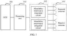
- a MIMO radar system may include an antenna array 101, a microwave integrated circuit (monolithic microwave integrated circuit, MMIC) 102, and a processing unit 103.
- the antenna array 101 may include a plurality of transmit antennas and a plurality of receive antennas.
- the microwave integrated circuit 102 is configured to generate a radar signal, and further send the radar signal by using the antenna array 101.
- the radar signal includes a plurality of chirp signals. After the radar signal is sent, an echo signal is formed after reflection by one or more targets, and the echo signal is received by a receive antenna.
- the microwave integrated circuit 102 is further configured to perform processing such as conversion and sampling on the echo signal received by the antenna array 101, and transmit a processed echo signal to the processing unit 103.
- the processing unit 103 is configured to perform operations such as fast Fourier transformation (Fast Fourier Transformation, FFT) and signal processing on the echo signal, so as to determine information such as a distance, a speed, and an azimuth of a target based on the received echo signal.
- the processing unit 103 may be a device that has a processing function, such as a micro control unit (microcontroller unit, MCU), a central processing unit (central process unit, CPU), a digital signal processor (digital signal processor, DSP), a field-programmable gate array (field-programmable gate array, FPGA), a dedicated accelerator, or the like.
- the radar system shown in FIG. 1 may further include an electronic control unit (electronic control unit, ECU) 104, configured to control a vehicle based on information such as the distance, the speed, and the azimuth of the target obtained after processing by the processing unit 103, for example, determine a driving route of the vehicle, and control a speed of the vehicle.
- ECU electronic control unit
- a transmitter in this embodiment of this application may include a transmit antenna and a transmit channel in the microwave integrated circuit 102, and a receiver may include a receive antenna and a receive channel in the microwave integrated circuit 102.
- the transmit antenna and the receive antenna may be located on a printed circuit board (print circuit board, PCB), and the transmit channel and the receive channel may be located in a chip, that is, an AOB (antenna on PCB).
- the transmit antenna and the receive antenna may be located in a chip package, and the transmit channel and the receive channel may be located in a chip, that is, an AIP (antenna in package).
- a combination form is not specifically limited in this embodiment of this application. It should be understood that specific structures of the transmit channel and the receive channel are not limited in this embodiment of this application, provided that a corresponding transmit and receive function can be implemented.
- the entire radar system may include a plurality of cascaded radio frequency chips.
- a transmit antenna array and a receive antenna array are obtained by cascading a plurality of MIMOs, and an analog signal output by each radio frequency chip is connected to an analog to digital converter (analog digital converter, ADC) by using an interface, and the ADC transmits digital data to the processing unit 103, for example, an MCU, a DSP, an FPGA, a general processing unit (General Process Unit, GPU), and the like.
- the MMIC and the DSP may be integrated into one chip, referred to as a system on chip (System on chip, SOC).
- the MMIC, the ADC, and the processing unit 103 may be integrated into one chip to form an SOC.
- the entire vehicle may be installed with one or more radar systems, and is connected to the central processing unit by using an in-vehicle bus.
- the central processing unit controls one or more in-vehicle sensors, including one or more millimeter wave radar sensors.
- FIG. 2 is a functional block diagram of a vehicle 200 with a self-driving function according to an embodiment of this application.
- the vehicle 200 is configured in a fully or partially self-driving mode.
- the vehicle 200 may control the vehicle 200 itself when being in a self-driving mode, and may determine current states of the vehicle and a surrounding environment by using a manual operation, determine a possible behavior of at least one another vehicle in the surrounding environment, determine a confidence level corresponding to a possibility that the another vehicle performs the possible behavior, and control the vehicle 200 based on determined information.
- the vehicle 200 may be set to operate when not interacting with a person.
- the vehicle 200 may include various subsystems, such as a travel system 202, a sensor system 204, a control system 206, one or more peripheral devices 208, a power supply 210, a computer system 212, and a user interface 216.
- the vehicle 200 may include more or fewer subsystems, and each subsystem may include a plurality of elements.
- each subsystem and element of the vehicle 200 may be interconnected in a wired or wireless manner.
- the travel system 202 may include a component that powers the vehicle 200 for movement.
- the travel system 202 may include an engine 218, an energy source 219, a transmission device 220, and a wheel/tire 221.
- the engine 218 may be an internal combustion engine, an electromotor, an air compression engine, or another type of engine combination, such as a hybrid engine composed of a gas-fuel engine and an electromotor, and a hybrid engine composed of an internal combustion engine and an air compression engine.
- the engine 218 converts the energy source 219 into mechanical energy.
- Examples of the energy source 219 include gasoline, diesel, other petroleum-based fuels, propane, other compressed gas-based fuels, ethanol, solar cell panels, batteries, and other power sources.
- the energy source 219 may also provide energy for another system of the vehicle 200.
- the transmission device 220 may transmit mechanical power from the engine 218 to the wheel 221.
- the transmission device 220 may include a gearbox, a differential, and a drive shaft.
- the transmission device 220 may further include another device, such as a clutch.
- the drive shaft may include one or more shafts that can be coupled to one or more wheels 221.
- the sensor system 204 may include several sensors that sense surrounding environment information of the vehicle 200.
- the sensor system 204 may include a positioning system 222 (the positioning system may be a global positioning system (global positioning system, GPS) system, or may be a BeiDou system or another positioning system), an inertial measurement unit (inertial measurement unit, IMU) 224, a radar 226, a laser rangefinder 228, and a camera 230.
- the sensor system 204 may further include a sensor of an internal system of the monitored vehicle 200 (for example, an in-vehicle air quality monitor, a fuel gauge, and an engine oil temperature gauge). Sensor data from one or more of these sensors can be used to detect an object and its corresponding characteristics (a position, a shape, a direction, a speed, and the like). Such detection and identification is a key function of a safe operation of the vehicle 200.
- the positioning system 222 may be configured to estimate a geographical position of the vehicle 200.
- the IMU 224 is configured to sense a position and a direction change of the vehicle 200 based on an inertial acceleration.
- the IMU 224 may be a combination of an accelerometer and a gyroscope.
- the radar 226 may use a radio signal to sense a target within the surrounding environment of vehicle 200.
- the radar 226 may be configured to sense a speed and/or a heading direction of the target.
- the radar 226 may be implemented by using the MIMO radar system shown in FIG. 1 .
- the laser rangefinder 228 may use laser to sense a target in an environment in which the vehicle 100 is located.
- the laser rangefinder 228 may include one or more laser sources, a laser scanner, and one or more detectors, as well as another system component.
- the camera 230 may be configured to capture a plurality of images of the surrounding environment of the vehicle 200.
- the camera 230 may be a static camera or a video camera.
- the control system 206 controls operations of the vehicle 200 and its components.
- the control system 206 may include various elements, including a steering system 232, an accelerator 234, a brake unit 236, a sensor fusion algorithm 238, a computer vision system 240, a route control system 242, and an obstacle avoidance system 244.
- the steering system 232 may be operated to adjust the heading direction of the vehicle 200.
- the steering system 232 may be a steering wheel system.
- the accelerator 234 is configured to control an operating speed of the engine 218 and further control the speed of the vehicle 200.
- the brake unit 236 is configured to control the vehicle 200 to decelerate.
- the brake unit 236 may use a force of friction to slow the wheel 221.
- the brake unit 236 may convert kinetic energy of the wheel 221 into a current.
- the brake unit 236 may alternatively use another form to slow a rotation speed of the wheel 221 to control the speed of the vehicle 200.
- the computer vision system 240 may be operated to process and analyze the images captured by the camera 230 to identify a target and/or a feature in the surrounding environment of the vehicle 200.
- the target and/or the feature may include a traffic signal, a road boundary, and an obstacle.
- the computer vision system 240 may use an object identification algorithm, a structure from motion (structure from motion, SFM) algorithm, a video tracking technology, and another computer vision technology.
- the computer vision system 240 may be configured to map an environment, track a target, estimate a speed of the target, and the like.
- the route control system 242 is configured to determine a driving route of the vehicle 200.
- the route control system 242 may combine data from the sensor 238, the GPS 222, and one or more predetermined maps to determine the driving route for the vehicle 200.
- the obstacle avoidance system 244 is configured to identify, assess, and avoid, or otherwise cross, a potential obstacle in the environment of the vehicle 200.
- control system 206 may add components or alternatively include components other than those shown and described. Alternatively, some of the components shown above may be reduced.
- the vehicle 200 interacts with an external sensor, another vehicle, another computer system, or a user by using the peripheral device 208.
- the peripheral device 208 may include a wireless communications system 246, a vehicle-mounted computer 248, a microphone 250, and/or a speaker 252.
- the peripheral device 208 provides a means for a user of the vehicle 200 to interact with the user interface 216.
- the vehicle-mounted computer 248 may provide information to the user of the vehicle 200.
- the user interface 216 may further be used to operate the vehicle-mounted computer 248 to receive input from the user.
- the vehicle-mounted computer 248 may be operated by using a touchscreen.
- the peripheral device 208 may provide a means for the vehicle 200 to communicate with another device located in the vehicle.
- the microphone 250 may receive audio (for example, a voice command or another audio input) from the user of the vehicle 200.
- the speaker 252 may output audio to the user of the vehicle 200.
- the wireless communications system 246 may communicate wirelessly with one or more devices directly or via a communications network.
- the wireless communications system 246 may use 3G cellular communications such as code division multiple access (code division multiple access, CDMA), EVD0, global system for mobile communications (global system for mobile communications, GSM)/general packet radio service (general packet radio service, GPRS), or 4G cellular communications such as long term evolution (long term evolution, LTE), or 5G cellular communications.
- the wireless communications system 246 may communicate with a wireless local area network (wireless local area network, WLAN) by using Wi-Fi.
- the wireless communications system 246 may communicate directly with a device by using an infrared link, Bluetooth, or ZigBee.
- the wireless communications system 246 may include one or more dedicated short range communications (dedicated short range communications, DSRC) devices, which may include common and/or private data communication between the vehicle and/or a roadside station.
- DSRC dedicated short range communications
- the power supply 210 may provide power to various components of the vehicle 200.
- the power supply 210 may be a rechargeable lithium ion or lead-acid battery.
- One or more battery packs of such battery may be configured as a power supply to supply power to various components of the vehicle 200.
- the power supply 210 and the energy source 219 may be implemented together, such as in some fully electric vehicles.
- the computer system 212 may include at least one processor 223.
- the processor 223 executes an instruction 225 stored in a non-transitory computer-readable medium such as a memory 224.
- the computer system 212 may further control a plurality of computing devices in an individual component or subsystem of the vehicle 200 in a distributed manner.
- the processor 223 may be any conventional processor, such as a commercially available central processing unit (central processing unit, CPU). Alternatively, the processor may be a dedicated device of an application-specific integrated circuit (application specific integrated circuit, ASIC) or another hardware-based processor.
- FIG. 2 functionally shows the processor, the memory, and other elements of the computer 210 in a same block, a person of ordinary skill in the art should understand that the processor, the computer, or the memory may actually include a plurality of processors, computers, or memories that may or may not be stored in a same physical housing.
- the memory may be a hard disk drive or another storage medium located in a housing different from the computer 210.
- references to the processor or the computer will be understood as including references to a set of processors, computers, or memories that may or may not operate in parallel.
- some components such as a steering component and a deceleration component, may have respective processors.
- the processor performs only calculation related to component-specific functions.
- the processor may be remote from the vehicle and communicate wirelessly with the vehicle.
- some of processes described herein are performed by a processor disposed in the vehicle, and others are performed by a remote processor, including taking necessary steps to perform a single operation.
- the memory 224 may include the instruction 225 (for example, program logic), and the instruction 225 may be executed by the processor 223 to perform various functions of the vehicle 200, including those functions described above.
- the memory 214 may also include additional instructions, including instructions to send data to, receive data from, interact with, and/or control one or more of the travel system 202, the sensor system 204, the control system 206, and the peripheral device 208.
- the memory 224 may further store data, such as a road map, route information, a position, a direction, and a speed that are of a vehicle, other such vehicle data, and other information. Such information may be used by the vehicle 200 and the computer system 212 during operation of the vehicle 200 in an autonomous, semi-autonomous, and/or manual mode.
- the user interface 216 is configured to provide information to or receive information from the user of the vehicle 200.
- the user interface 216 may include one or more input/output devices within a set of peripheral devices 208, such as the wireless communications system 246, the vehicle-mounted computer 248, the microphone 250, and the speaker 252.
- the computer system 212 may control functions of the vehicle 200 based on input received from various subsystems (for example, the travel system 202, the sensor system 204, and the control system 206) and from the user interface 216. For example, the computer system 212 may use input from the control system 206 to control the steering unit 232 to avoid an obstacle detected by the sensor system 204 and the obstacle avoidance system 244. In some embodiments, the computer system 212 may be operated to control many aspects of the vehicle 200 and its subsystems.
- various subsystems for example, the travel system 202, the sensor system 204, and the control system 206
- the computer system 212 may use input from the control system 206 to control the steering unit 232 to avoid an obstacle detected by the sensor system 204 and the obstacle avoidance system 244.
- the computer system 212 may be operated to control many aspects of the vehicle 200 and its subsystems.
- one or more of the foregoing components may be separately installed or associated with the vehicle 200.
- the memory 224 may partially or completely exist separately from the vehicle 200.
- the foregoing components may be communicatively coupled together in a wired and/or wireless manner.
- FIG. 2 should not be understood as a limitation on this embodiment of this application.
- a self-driving vehicle traveling on a road may identify a target in its surrounding environment to determine adjustment to a current speed.
- the target may be another vehicle, a traffic control device, or another type of target.
- each identified target may be considered independently and may be used to determine a to-be-adjusted speed for the self-driving vehicle based on characteristics of the target, such as its current speed, acceleration, and spacing from the vehicle.
- the self-driving vehicle 200 or a computing device associated with the self-driving vehicle 200 may predict a behavior of the identified target based on the characteristics of the identified target and a state of the surrounding environment (for example, traffic, rain, and ice on a road).
- a state of the surrounding environment for example, traffic, rain, and ice on a road.
- all identified targets depend on each other's behaviors. Therefore, all the identified targets may be considered together to predict a behavior of a single identified target.
- the vehicle 200 can adjust its speed based on the predicted behavior of the identified target.
- the self-driving vehicle can determine, based on the predicted behavior of the target, a stable state to which the vehicle needs to be adjusted (for example, acceleration, deceleration, or stop).
- a stable state to which the vehicle needs to be adjusted for example, acceleration, deceleration, or stop.
- another factor may also be considered to determine the speed of the vehicle 200, such as a transverse position of the vehicle 200 on a traveling road, a curvature of the road, and proximity between static and dynamic targets.
- the computing device may also provide an instruction to modify a steering angle of the vehicle 200, so that the self-driving vehicle follows a given track and/or maintains a safe transverse and longitudinal distance from a target (for example, a car in an adjacent lane on a road) near the self-driving vehicle.
- a target for example, a car in an adjacent lane on a road
- the vehicle 200 may be a car, a truck, a motorcycle, a bus, a boat, an airplane, a helicopter, a lawn mower, a recreational vehicle, a playground vehicle, a construction device, a trolley, a golf cart, a train, a handcart, or the like. This is not specifically limited in this embodiment of this application.
- the radar system in this embodiment of this application may be applied to a plurality of fields.
- the radar system in this embodiment of this application includes but is not limited to an in-vehicle radar, a roadside traffic radar, and an unmanned aerial vehicle radar.
- this application provides a radar signal transmitting and receiving method.
- the method is applied to a MIMO radar.
- the MIMO radar includes a transmitter, a receiver, and a processing unit.
- the transmitter includes N Tx transmit antennas
- the receiver includes N Rx receive antennas. Both N Tx and N Rx are positive integers greater than or equal to 2. It should be understood that a specific structure of the MIMO radar may be shown in FIG. 1 , or may not be limited to the specific structure of FIG. 1 . This is not limited in this application.
- the method includes the following steps.
- Step 400 The processing unit determines configuration information of a measurement frame, where the configuration information of the measurement frame indicates a preset transmit sequence of the N Tx transmit antennas, transmit duration T c of each chirp signal, and a quantity N slow of times that the N Tx transmit antennas perform repeated transmission according to the preset transmit sequence.
- the configuration information of the measurement frame includes the preset transmit sequence of the N Tx transmit antennas, T c , and N slow , or the preset transmit sequence of the N Tx transmit antennas, U ⁇ T c , and N slow . It should be understood that a specific form of the configuration information of the measurement frame is not limited in this application.
- the processing unit After determining the configuration information of the measurement frame, the processing unit sends the configuration information of the measurement frame to a single MMIC or a plurality of MMICs by using an interface, where the single MMIC or the plurality of MMICs is or are used to enable the transmitter based on the configuration information of the measurement frame to send the measurement frame.
- Step 410 The transmitter sends the measurement frame based on the configuration information of the measurement frame, where the measurement frame includes U ⁇ N slow chirp signals, the U ⁇ N slow chirp signals include N slow groups of chirp signals, each group of chirp signals includes U chirp signals, the U chirp signals are respectively transmitted by the N Tx transmit antennas in U timeslots according to the preset transmit sequence, and transmit duration T c of each chirp signal is denoted as one timeslot; and a virtual receive array formed by the N Tx transmit antennas and the N Rx receive antennas includes overlapping elements whose transmit interval is N 1 and overlapping elements whose transmit interval is N 2 , N 1 ⁇ N 2 , N 1 is a positive integer, N 2 is a positive integer, and U ⁇ N Tx .
- a transmit antenna m1 transmits a chirp signal in a timeslot u 1 of the U timeslots, a position of a virtual receive antenna element formed by the transmit antenna m 1 and a receive antenna n 1 is d m 1 n 1
- a transmit antenna m 1' transmits a chirp signal in a timeslot u 1 ' of the U timeslots
- a position of a virtual receive antenna element formed by the transmit antenna m 1' and a receive antenna n 1' is d m 1 'n 1'
- a transmit antenna m 2 transmits a chirp signal in a timeslot u 2 of the U timeslots
- a position of a virtual receive antenna element formed by the transmit antenna m 2 and a receive antenna n 2 is d m 2 n 2
- a transmit antenna m 2' transmits a chirp signal in a timeslot u 2 ' of the U timeslots
- the measurement frame may be an FMCW, or may use a waveform used by another MIMO radar.
- the measurement frame may be a waveform such as a pulse waveform or an orthogonal frequency division multiplexing (Orthogonal Frequency Division Multiplex, OFDM).
- N 1 and N 2 are relatively prime.
- values of N 1 and N 2 are determined based on the antenna layout and the preset sequence. It may be understood that, because a smaller value of the transmit interval indicates a larger corresponding speed measurement range, a fewer times of aliasing may be implemented. Therefore, the values of N 1 and N 2 are generally relatively small.
- the virtual receive array formed by the N Tx transmit antennas and the N Rx receive antennas includes overlapping elements whose transmit interval is N 3 , N 1 ⁇ N 2 ⁇ N 3 , and N 3 is a positive integer.
- Conventional virtual receive antenna An antenna obtained by combining a transmit antenna and a receive antenna is a virtual receive antenna, which may also be described as that a transmit antenna and a receive antenna are combined to obtain a virtual receive array.
- a quantity of transmit antennas is N Tx
- a quantity of receive antennas is N Rx .
- a coordinate position of a transmit antenna Tx i is represented as ( x i , y i ) in a two-dimensional plane, where 1 ⁇ i ⁇ N Tx ;
- a coordinate position of a receive antenna Rx i is represented as ( x i , y i ) in a two-dimensional plane, where 1 ⁇ j ⁇ N Rx ; and a total of N Tx ⁇ N Rx virtual elements may be obtained.
- k (u - 1) * N Rx + n Rx , 1 ⁇ k ⁇ U * N Rx , 1 ⁇ u ⁇ U, 1 ⁇ n Rx ⁇
- a coordinate position of the transmit antenna m is represented as ( x m ,y m ) u in a two-dimensional plane, where 1 ⁇ m ⁇ N Tx
- a coordinate position of the receive antenna n is represented as ( x n ,y n ) u in a two-dimensional plane, where 1 ⁇ n ⁇ N Rx .
- a method for forming the overlapping elements may further be described herein in the following two manners, but is not limited to the following two manners: Manner 1: Overlapping elements are formed by deployment of different antennas.
- the overlapping elements formed by using manner 1 may also be referred to as overlapping elements on hardware.
- a one-dimensional array refers to a case in which vertical Y-axis coordinate positions of all elements in a transmit antenna array are the same, and vertical Y-axis coordinate positions of all elements in a receive antenna array are the same.
- the one-dimensional array can be used to obtain only a horizontal angle of a target, that is, a horizontal array.
- a two-dimensional array refers to a case in which a position of at least one element is different from that of another element in Y-axis coordinates of all elements in a transmit antenna array, and a position of one element is different from that of another element in Y-axis coordinates of all elements in a receive antenna array.
- the two-dimensional array includes one or more one-dimensional subarrays.
- FIG. 3 is a schematic diagram of two pairs of overlapping elements formed by a one-dimensional horizontal array with three transmit antennas and four receive antennas (referred to as 3 transmit 4 receive (3T4R)).
- a spacing between the transmit antennas is 3 ⁇ /2 of the horizontal array, and a spacing between the receive antennas is ⁇ /2 of the horizontal array, where ⁇ is a half wavelength.
- At least one transmit antenna in the N Tx transmit antennas transmits a chirp signal twice in the U transmit timeslots.
- the overlapping elements formed in manner 1 may also be referred to as overlapping elements on software or soft overlapping elements.
- the transmit sequence is 2-2-1-1-1-2-3-3-2-3-3-1. It should be understood that the transmit sequence is merely an example, and is not limited in this application. The following describes the soft overlapping elements and a corresponding transmit interval based on FIG. 6(a) to FIG. 6(c).
- 1 and 1 marked by a bold line form four pairs of overlapping elements on the receive side, and transmit intervals of the four pairs of overlapping elements are the same and are all 2.
- 3 and 3 marked by a bold line form four pairs of overlapping elements on the receive side, and transmit intervals of the four pairs of overlapping elements are the same and are all 2.
- connection line As shown in FIG. 6(c), 2 and 2 connected by a connection line form four pairs of overlapping elements on the receive side, and transmit intervals of the four pairs of overlapping elements are the same and are all 3. Similarly, two pairs of 3 and 3 connected by connection lines form 2 ⁇ 4 pairs of overlapping elements on the receive side, and transmit intervals of the eight pairs of overlapping elements are the same and are all 3.
- the soft overlapping elements do not cause loss of an aperture. Although a maximum speed measurement range corresponding to a maximum MIMO is reduced due to U> N Tx , this method does not affect transmit duration Tc of each chirp. Therefore, a system can finally recover to the maximum test range determined by using the Tc and keep it unchanged. It may be understood that, if the two manners are combined, a quantity of overlapping elements may be further increased.
- the overlapping elements formed in manner 1 include the following: Overlapping elements whose transmit interval is 1 are successively as follows: The transmit antenna 2 and the transmit antenna 1 (represented by 2-1) form one pair of overlapping elements on the receive side, the transmit antenna 1 and the transmit antenna 2 (represented by 1-2) form one pair of overlapping elements on the receive side, the transmit antenna 3 and the transmit antenna 2 (represented by 3-2) form one pair of overlapping elements on the receive side, and the transmit antenna 2 and the transmit antenna 3 (represented by 2-3) form one pair of overlapping elements on the receive side.
- Overlapping elements whose transmit interval is 2 are successively as follows:
- the transmit antenna 2 and the one-antenna-spaced transmit antenna 1 form one pair of overlapping elements on the receive side
- the transmit antenna 1 and the one-antenna-spaced transmit antenna 2 (represented by 1-1-2) form one pair of overlapping elements on the receive side
- the transmit antenna 3 and the one-antenna-spaced transmit antenna 2 (represented by 3-3-2) form one pair of overlapping elements on the receive side
- the transmit antenna 2 and the one-antenna-spaced transmit antenna 3 (represented by 2-3-3) form one pair of overlapping elements on the receive side.
- a quantity of overlapping elements whose transmit interval is 3 and a quantity of overlapping elements whose transmit interval is another transmit interval may be further counted in the two manners. This is not limited in this application.
- overlapping elements with a plurality of transmit intervals can be constructed, and a quantity of overlapping elements can be increased.
- there are a relatively small quantity of overlapping elements and overlapping elements with a single transmit interval when a phase difference between overlapping elements is greatly affected by noise, correct speed solving of a target is directly affected.
- overlapping elements with a plurality of transmit intervals are constructed, and there are a relatively large quantity of overlapping elements.
- phase differences between a plurality of overlapping elements with a plurality of transmit intervals may be processed, to effectively reduce impact, on speed solving, of the phase differences between the overlapping elements that are greatly affected by noise, thereby improving accuracy of speed solving of the target.
- Step 420 The receiver receives an echo signal that is sent by the transmitter and that is formed after the measurement frame is reflected by one or more targets.
- the receiver includes N Rx receive antennas.
- the N Rx receive antennas receive U received signals according to the transmit sequence of the N Tx transmit antennas, and then convert the received U received signals into echo signals based on a position relationship between the N Tx transmit antennas and the N Rx receive antennas and the transmit sequence of the transmit antennas.
- N slow is a quantity of times of repeated transmission according to the preset sequence.
- U represents a quantity of timeslots in which different antennas transmit signals in a repetition period according to a TDM manner, and a transmission period is U ⁇ T c , where a same antenna may perform transmission a plurality of times in U timeslots.
- one of the U received signals is a chirp signal formed after a transmitted chirp signal is reflected by one or more targets.
- Step 430 The processing unit determines a first aliasing coefficient and a second aliasing coefficient.
- the first aliasing coefficient is an aliasing coefficient corresponding to overlapping elements whose transmit interval is N 1 and corresponding to a first target
- the second aliasing coefficient is an aliasing coefficient corresponding to overlapping elements whose transmit interval is N 2 and corresponding to the first target
- the first target is any target in the at least one target.
- a single chirp signal is referred to as fast chirp (fast chirp), and distance information of a target may be obtained.
- a plurality of chirp signals are referred to as slow chirp (slow chirp), and speed information of the target may be obtained.
- the processing unit calculates fast Fourier transformation in a distance dimension and corresponding to each fast chirp, and further, on a basis of fast chirp fft, calculates fast Fourier transformation in a speed dimension on different slow chirps on a same distance unit (Range bin) to obtain two-dimensional Fourier transformation results of U ⁇ N Rx virtual receive elements.
- a two-dimensional Fourier transformation result of one virtual receive element refers to a range-Doppler map (Range-Doppler Map) corresponding to the virtual receive element.
- Range-Doppler Map range-Doppler map
- the processing unit accumulates the two-dimensional Fourier transformation results of the U ⁇ N Rx virtual receive elements to obtain a total RD map.
- accumulation of the two-dimensional Fourier transformation results of the U ⁇ N Rx virtual receive elements refers to accumulation of the RD maps respectively corresponding to the U ⁇ N Rx virtual receive elements to obtain a total RD map.
- Accumulation of the two-dimensional Fourier transformation results of the U ⁇ N Rx virtual receive elements may be performed by using incoherent superposition.
- amplitudes of the two-dimensional Fourier of the U ⁇ N Rx virtual receive elements are superposed, or incoherent superposition is performed. That is, complex numbers of peaks synthesized on a fixed beam of the two-dimensional Fourier of the U ⁇ N Rx virtual receive elements are superposed, or in another superposition manner, which is not particularly limited in this application.
- the RD map is a radar output map in which one dimension is distance information, and one dimension is Doppler information.
- a group of data extracted from the distance dimension is referred to data corresponding to a same distance unit (range bin)
- a group of data extracted from the Doppler dimension is referred to as data corresponding to a same Doppler bin (Doppler bin)
- a group of data extracted from both the distance and Doppler dimensions is referred to as data corresponding to a same range-Doppler cell (Range-Doppler Cell).
- the processing unit detects a target on the total RD map.
- the processing unit may perform detection by using various existing detection methods, for example, commonly used detection methods such as ordered statistic-constant false alarm rate (detection) (Ordered Statistic-Constant False Alarm Rate, OS-CFAR) or cell-averaging constant false alarm rate (detection) (Cell-Averaging Constant False Alarm Rate, CA-CFAR). This is not limited in this application.
- detection ordered statistic-constant false alarm rate
- OS-CFAR Orderered Statistic-Constant False Alarm Rate
- CA-CFAR Cell-Averaging Constant False Alarm Rate
- the processing unit After the processing unit detects a target on the total RD map, the processing unit extracts signals that are on the total RD map and that are of overlapping elements corresponding to the target.
- Signals that are on the total RD map and that are of overlapping elements corresponding to each target include signals that are on the total RD map and that are of overlapping elements whose transmit interval is N 1 and signals that are on the total RD map and that are of overlapping elements whose transmit interval is N 2 .
- the processing unit may determine the first aliasing coefficient in the following nonrestrictive manner, and the processing unit may determine the second aliasing coefficient in a same manner. Repeated content is not to be described.
- a transmit antenna m transmits a chirp signal in a timeslot u of U timeslots, a position of a virtual receive antenna element formed by the transmit antenna m and a receive antenna n is d mn
- a transmit antenna m ' transmits a chirp signal in a timeslot u ' of the U timeslots
- a position of a virtual receive antenna element formed by the transmit antenna m ' and a receive antenna n ' is d m'n'
- N ii
- a transmit interval corresponding to the overlapping elements is N ii .
- the transmit antenna m transmits a chirp signal in the timeslot u of the U timeslots. If a waveform of the signal is represented as S(t), after the signal is reflected by a target whose distance is R i , radial speed is V i , and horizontal angle (the horizontal angle is used as an example) is ⁇ i , data of the virtual receive element formed by the transmit antenna m and the receive antenna n corresponds to data that is in the RD map and whose target distance and aliased speed are ( R ind , V ind ) .
- S mn u is a signal corresponding to d mn in the RD map corresponding to the virtual receive element
- S m ′ n ′ u is a signal corresponding to d m ' n ' in the RD map corresponding to the virtual receive element
- the value range of k N ii is determined based on a transmit interval N ii .
- an average value of k N ii is separately obtained based on all overlapping elements whose transmit interval is N ii , and is used as an aliasing coefficient corresponding to overlapping elements whose transmit interval is N ii and corresponding to the target.
- Step 440 The processing unit determines a speed of the first target based on the first aliasing coefficient and the second aliasing coefficient.
- the processing unit may determine the speed of the first target by using, but not limited to, the following methods: First, the processing unit determines a first aliasing coefficient range based on N 1 , and determines a second aliasing coefficient range based on N 2 .
- Speed measurement ranges corresponding to overlapping elements with different transmit intervals are different.
- speed measurement ranges of overlapping elements that are adjacently sent in time (to be specific, a transmit interval is 1), namely,
- overlapping elements whose transmit interval is 1 may obtain U times of expansion of the speed of the target, compared with the MIMO radar whose transmit period is U, and the aliasing coefficient has U values.
- Overlapping elements whose transmit interval is N ii may obtain U/N ii times of expansion of the speed of the target, compared with the MIMO radar whose transmit period is U, and an aliasing coefficient corresponding to the overlapping elements whose transmit interval is N ii has U/N ii values.
- the aliasing coefficient may use 1, 2, ..., and U/N ii , which specifically indicate multiples of aliasing 0, 1, ..., and U/N ii - 1. 0 indicates that there is no overlapping.
- a positive or negative relationship of a vehicle environment speed may be converted after a plurality of groups of N ii or may be converted here. An example of this application is merely described by using conversion after a plurality of groups of N ii as an example.
- an aliasing coefficient range corresponding to overlapping elements whose transmit interval is N 1 may be 0, 1, ..., U/ (N 1 -1), and an aliasing coefficient range corresponding to overlapping elements whose transmit interval is N 2 is 0, 1, ..., U/( N 2 -1 ).
- the processing unit determines the first aliasing coefficient set based on the first aliasing coefficient range, the first aliasing coefficient, and N 1 , and determines the second aliasing coefficient set based on the second aliasing coefficient range, the second aliasing coefficient, and N 2 .
- the first aliasing coefficient set includes a possible aliasing coefficient that converts the first aliasing coefficient to a third aliasing coefficient range
- the second aliasing coefficient set includes a possible aliasing coefficient that converts the second aliasing coefficient to the third aliasing coefficient range
- the third aliasing coefficient range is an aliasing coefficient range corresponding to overlapping elements whose transmit interval is 1.
- V i _ overlap N ii V i _ amb + 2 ⁇ k N ii ⁇ V max (Formula 3)
- V i _ overlap N ii value ranges corresponding to overlapping elements with different transmit intervals are different, and V i _ amb corresponding to overlapping elements with different transmit intervals is the same. Therefore, there is a conversion relationship between aliasing coefficients k N ii corresponding to overlapping elements with different transmit intervals. To reduce impact of noise on overlapping elements, aliasing coefficients corresponding to overlapping elements with different transmit intervals cannot be directly added for averaging or weighted averaging.
- N ii represents a transmit interval
- k N ii is an aliasing coefficient corresponding to overlapping elements whose transmit interval is N ii
- k is an aliasing coefficient obtained by converting the aliasing coefficient corresponding to the overlapping elements whose transmit interval is N ii .
- N ii > 1
- j has a plurality of values. Therefore, a plurality of values of k are also referred to as an aliasing coefficient set, that is, a set of an aliasing coefficient that is corresponding to overlapping elements whose transmit interval is 1 and that is converted from the aliasing coefficient corresponding to the overlapping elements whose transmit interval is N ii .
- the processing unit determines a third aliasing coefficient and a fourth aliasing coefficient based on the first aliasing coefficient set and the second aliasing coefficient set.
- the third aliasing coefficient is one aliasing coefficient in the first aliasing coefficient set
- the fourth aliasing coefficient is one aliasing coefficient in the second aliasing coefficient set.
- a difference between the third aliasing coefficient and the fourth aliasing coefficient is a minimum value of a difference between any aliasing coefficient in the first aliasing coefficient set and any aliasing coefficient in the second aliasing coefficient set.
- processing unit processes the third aliasing coefficient and the fourth aliasing coefficient.
- the processing unit calculates an average value of the third aliasing coefficient and the fourth aliasing coefficient.
- the processing unit calculates a weighted average value of the third aliasing coefficient and the fourth aliasing coefficient.
- weights respectively corresponding to the third aliasing coefficient and the fourth aliasing coefficient may be determined based on quantities of overlapping elements with different transmit intervals, a signal-to-noise ratio on a channel, and the like.
- the following uses a target 1 as an example to describe a conversion process of an aliasing coefficient corresponding to overlapping elements with different transmit intervals and corresponding to the target 1.
- the aliasing coefficient is an aliasing coefficient corresponding to overlapping elements whose transmit interval is 1. Therefore, conversion is not required.
- the following uses a target 1 as an example to describe a conversion process of an aliasing coefficient corresponding to overlapping elements with different transmit intervals and corresponding to the target 1.
- the speed may be defined as positive or negative
- the aliasing coefficient range is [- U /2 , U /2]
- the aliasing coefficient range is [ -U /2 , U /2) .
- the aliased speed may be extended to a value in an entire U ⁇ N doppler range
- i represents an aliasing coefficient obtained by the first target by using overlapping elements with a plurality of groups of transmit intervals.
- i is an average value obtained based on k corresponding to the three different transmit intervals in Example 1.
- the processing unit obtains the speed of the first target based on obtained dopplerInd umamb and speed resolution. It may be understood that, N doppler is greater than or equal to N slow , and exceeded data is usually filled by using zero-padding.
- an embodiment of this application further provides a radar device 800.
- the radar device is a MIMO radar.
- the MIMO radar includes a transmitter 801, a receiver 802, and a processing unit 803.
- the transmitter includes N Tx transmit antennas, and the receiver includes N Rx receive antennas. Both N Tx and N Rx are positive integers greater than or equal to 2.
- the radar device 800 is configured to perform the foregoing method shown in FIG. 4 .
- a preset transmit sequence of N Tx transmit antennas may be used to construct overlapping elements with a plurality of transmit intervals and increase a quantity of overlapping elements.
- aliasing coefficients respectively corresponding to overlapping elements with a plurality of transmit intervals may be calculated based on the overlapping elements with a plurality of transmit intervals and a relatively large quantity of overlapping elements.
- embodiments of this application may be provided as a method, a system, or a computer program product. Therefore, embodiments of this application may use a form of hardware only embodiments, software only embodiments, or embodiments with a combination of software and hardware. Moreover, embodiments of this application may use a form of a computer program product that is implemented on one or more computer-usable storage media (including but not limited to a disk memory, a CD-ROM, an optical memory, and the like) that include computer-usable program code.
- computer-usable storage media including but not limited to a disk memory, a CD-ROM, an optical memory, and the like
- Embodiments of this application are described with reference to the flowcharts and/or block diagrams of the method, the device (system), and the computer program product according to embodiments of this application. It should be understood that computer program instructions may be used to implement each process and/or each block in the flowcharts and/or the block diagrams and a combination of a process and/or a block in the flowcharts and/or the block diagrams.
- the computer program instructions may be provided for a general-purpose computer, a dedicated computer, an embedded processor, or a processor of another programmable data processing device to generate a machine, so that the instructions executed by the computer or the processor of the another programmable data processing device generate an apparatus configured to implement a specific function in one or more procedures in the flowcharts and/or in one or more blocks in the block diagrams.
- the computer program instructions may alternatively be stored in a computer-readable memory that can indicate a computer or another programmable data processing device to work in a specific manner, so that the instructions stored in the computer-readable memory generate an artifact that includes an instruction apparatus.
- the instruction apparatus implements a specific function in one or more procedures in the flowcharts and/or in one or more blocks in the block diagrams.
- the computer program instructions may alternatively be loaded onto a computer or another programmable data processing device, so that a series of operations and steps are performed on the computer or the another programmable device, to generate computer-implemented processing. Therefore, the instructions executed on the computer or the another programmable device provide steps used to implement a specific function in one or more procedures in the flowcharts and/or in one or more blocks in the block diagrams.
Landscapes
- Engineering & Computer Science (AREA)
- Radar, Positioning & Navigation (AREA)
- Remote Sensing (AREA)
- Physics & Mathematics (AREA)
- Computer Networks & Wireless Communication (AREA)
- General Physics & Mathematics (AREA)
- Electromagnetism (AREA)
- Radar Systems Or Details Thereof (AREA)
Applications Claiming Priority (1)
| Application Number | Priority Date | Filing Date | Title |
|---|---|---|---|
| PCT/CN2020/080977 WO2021189268A1 (fr) | 2020-03-24 | 2020-03-24 | Procédé d'émission et de réception de signal radar, et radar |
Publications (2)
| Publication Number | Publication Date |
|---|---|
| EP4119979A1 true EP4119979A1 (fr) | 2023-01-18 |
| EP4119979A4 EP4119979A4 (fr) | 2023-05-31 |
Family
ID=77890896
Family Applications (1)
| Application Number | Title | Priority Date | Filing Date |
|---|---|---|---|
| EP20926758.2A Pending EP4119979A4 (fr) | 2020-03-24 | 2020-03-24 | Procédé d'émission et de réception de signal radar, et radar |
Country Status (3)
| Country | Link |
|---|---|
| EP (1) | EP4119979A4 (fr) |
| CN (1) | CN115315636B (fr) |
| WO (1) | WO2021189268A1 (fr) |
Cited By (1)
| Publication number | Priority date | Publication date | Assignee | Title |
|---|---|---|---|---|
| WO2024209372A1 (fr) * | 2023-04-05 | 2024-10-10 | Mobileye Vision Technologies Ltd. | Appareil radar, système et procédé |
Families Citing this family (4)
| Publication number | Priority date | Publication date | Assignee | Title |
|---|---|---|---|---|
| US11822005B2 (en) * | 2021-02-26 | 2023-11-21 | Nxp B.V. | Radar communications with offset chirp interval time |
| US11815585B2 (en) | 2021-02-27 | 2023-11-14 | Nxp Usa, Inc. | Method and system for time division multiplexing MIMO radar doppler compensation using spurious angle spectrum hypothesis tests |
| US12066520B2 (en) | 2021-04-19 | 2024-08-20 | Nxp B.V. | Radar communications with disparate pulse repetition intervals |
| CN115656961B (zh) * | 2022-12-26 | 2023-03-10 | 南京楚航科技有限公司 | 一种基于并行处理器的os-cfar处理方法及系统 |
Family Cites Families (11)
| Publication number | Priority date | Publication date | Assignee | Title |
|---|---|---|---|---|
| CN103777180B (zh) * | 2014-01-24 | 2016-04-06 | 深圳大学 | Mimo雷达系统及其目标端相位同步方法 |
| DE102014212284A1 (de) * | 2014-06-26 | 2015-12-31 | Robert Bosch Gmbh | MIMO-Radarmessverfahren |
| US10627483B2 (en) * | 2016-07-09 | 2020-04-21 | Texas Instruments Incorporated | Methods and apparatus for velocity detection in MIMO radar including velocity ambiguity resolution |
| JP6853642B2 (ja) * | 2016-09-26 | 2021-03-31 | パナソニック株式会社 | レーダ装置 |
| US20180166794A1 (en) * | 2016-12-14 | 2018-06-14 | GM Global Technology Operations LLC | 2d-mimo radar antenna array geometry and design method |
| KR102429767B1 (ko) * | 2017-04-11 | 2022-08-05 | 한국전자통신연구원 | 스위치드 배열 안테나 레이더를 위한 자가 교정 방법 |
| CN108594233B (zh) * | 2018-04-24 | 2020-07-14 | 森思泰克河北科技有限公司 | 一种基于mimo汽车雷达的速度解模糊方法 |
| CN108933749B (zh) * | 2018-06-08 | 2021-01-15 | 天津大学 | 混叠广义频分复用多载波调制系统 |
| CN109085541B (zh) * | 2018-09-07 | 2021-02-02 | 杭州捍鹰科技有限公司 | Mimo雷达阵列天线及其信号处理方法 |
| CN109444891B (zh) * | 2019-01-08 | 2024-07-23 | 浙江力邦合信智能制动系统股份有限公司 | 一种毫米波雷达天线系统及解耦方法 |
| CN110412558B (zh) * | 2019-07-03 | 2022-05-17 | 南京理工大学 | 基于tdm mimo的解车载fmcw雷达速度模糊方法 |
-
2020
- 2020-03-24 CN CN202080098931.3A patent/CN115315636B/zh active Active
- 2020-03-24 EP EP20926758.2A patent/EP4119979A4/fr active Pending
- 2020-03-24 WO PCT/CN2020/080977 patent/WO2021189268A1/fr not_active Ceased
Cited By (1)
| Publication number | Priority date | Publication date | Assignee | Title |
|---|---|---|---|---|
| WO2024209372A1 (fr) * | 2023-04-05 | 2024-10-10 | Mobileye Vision Technologies Ltd. | Appareil radar, système et procédé |
Also Published As
| Publication number | Publication date |
|---|---|
| WO2021189268A1 (fr) | 2021-09-30 |
| CN115315636A (zh) | 2022-11-08 |
| EP4119979A4 (fr) | 2023-05-31 |
| CN115315636B (zh) | 2025-08-26 |
Similar Documents
| Publication | Publication Date | Title |
|---|---|---|
| US12517217B2 (en) | Radar signal transmitting method, radar signal receiving method, and apparatus | |
| US12386053B2 (en) | Velocity ambiguity resolving method and echo signal processing apparatus | |
| US12111387B2 (en) | Signal processing method, radar system, and vehicle | |
| US12541018B2 (en) | Signal transmission method and apparatus, signal processing method and apparatus, and radar system | |
| EP4119979A1 (fr) | Procédé d'émission et de réception de signal radar, et radar | |
| US12253624B2 (en) | Signal transmission method and apparatus, signal processing method and apparatus, and radar system | |
| EP4080235B1 (fr) | Procédé et appareil d'estimation de champ proche | |
| WO2022020995A1 (fr) | Procédé et dispositif de traitement de signal et support de stockage | |
| CN115917355B (zh) | 信号处理方法及装置、雷达装置、存储介质 |
Legal Events
| Date | Code | Title | Description |
|---|---|---|---|
| STAA | Information on the status of an ep patent application or granted ep patent |
Free format text: STATUS: THE INTERNATIONAL PUBLICATION HAS BEEN MADE |
|
| PUAI | Public reference made under article 153(3) epc to a published international application that has entered the european phase |
Free format text: ORIGINAL CODE: 0009012 |
|
| STAA | Information on the status of an ep patent application or granted ep patent |
Free format text: STATUS: REQUEST FOR EXAMINATION WAS MADE |
|
| 17P | Request for examination filed |
Effective date: 20221013 |
|
| AK | Designated contracting states |
Kind code of ref document: A1 Designated state(s): AL AT BE BG CH CY CZ DE DK EE ES FI FR GB GR HR HU IE IS IT LI LT LU LV MC MK MT NL NO PL PT RO RS SE SI SK SM TR |
|
| REG | Reference to a national code |
Ref country code: DE Ref legal event code: R079 Free format text: PREVIOUS MAIN CLASS: G01S0013580000 Ipc: G01S0013340000 |
|
| A4 | Supplementary search report drawn up and despatched |
Effective date: 20230502 |
|
| RIC1 | Information provided on ipc code assigned before grant |
Ipc: G01S 13/58 20060101ALI20230424BHEP Ipc: G01S 13/931 20200101ALI20230424BHEP Ipc: G01S 13/42 20060101ALI20230424BHEP Ipc: G01S 13/34 20060101AFI20230424BHEP |
|
| DAV | Request for validation of the european patent (deleted) | ||
| DAX | Request for extension of the european patent (deleted) | ||
| RAP1 | Party data changed (applicant data changed or rights of an application transferred) |
Owner name: SHENZHEN YINWANG INTELLIGENTTECHNOLOGIES CO., LTD. |
|
| GRAP | Despatch of communication of intention to grant a patent |
Free format text: ORIGINAL CODE: EPIDOSNIGR1 |
|
| STAA | Information on the status of an ep patent application or granted ep patent |
Free format text: STATUS: GRANT OF PATENT IS INTENDED |