EP4119982B1 - Dispositif de surveillance et procédé de fonctionnement d'un dispositif de surveillance - Google Patents
Dispositif de surveillance et procédé de fonctionnement d'un dispositif de surveillance Download PDFInfo
- Publication number
- EP4119982B1 EP4119982B1 EP21186165.3A EP21186165A EP4119982B1 EP 4119982 B1 EP4119982 B1 EP 4119982B1 EP 21186165 A EP21186165 A EP 21186165A EP 4119982 B1 EP4119982 B1 EP 4119982B1
- Authority
- EP
- European Patent Office
- Prior art keywords
- contour detection
- monitoring device
- protective field
- field
- detection fields
- Prior art date
- Legal status (The legal status is an assumption and is not a legal conclusion. Google has not performed a legal analysis and makes no representation as to the accuracy of the status listed.)
- Active
Links
Images

Classifications
-
- F—MECHANICAL ENGINEERING; LIGHTING; HEATING; WEAPONS; BLASTING
- F16—ENGINEERING ELEMENTS AND UNITS; GENERAL MEASURES FOR PRODUCING AND MAINTAINING EFFECTIVE FUNCTIONING OF MACHINES OR INSTALLATIONS; THERMAL INSULATION IN GENERAL
- F16P—SAFETY DEVICES IN GENERAL; SAFETY DEVICES FOR PRESSES
- F16P3/00—Safety devices acting in conjunction with the control or operation of a machine; Control arrangements requiring the simultaneous use of two or more parts of the body
- F16P3/12—Safety devices acting in conjunction with the control or operation of a machine; Control arrangements requiring the simultaneous use of two or more parts of the body with means, e.g. feelers, which in case of the presence of a body part of a person in or near the danger zone influence the control or operation of the machine
- F16P3/14—Safety devices acting in conjunction with the control or operation of a machine; Control arrangements requiring the simultaneous use of two or more parts of the body with means, e.g. feelers, which in case of the presence of a body part of a person in or near the danger zone influence the control or operation of the machine the means being photocells or other devices sensitive without mechanical contact
- F16P3/144—Safety devices acting in conjunction with the control or operation of a machine; Control arrangements requiring the simultaneous use of two or more parts of the body with means, e.g. feelers, which in case of the presence of a body part of a person in or near the danger zone influence the control or operation of the machine the means being photocells or other devices sensitive without mechanical contact using light grids
-
- G—PHYSICS
- G01—MEASURING; TESTING
- G01S—RADIO DIRECTION-FINDING; RADIO NAVIGATION; DETERMINING DISTANCE OR VELOCITY BY USE OF RADIO WAVES; LOCATING OR PRESENCE-DETECTING BY USE OF THE REFLECTION OR RERADIATION OF RADIO WAVES; ANALOGOUS ARRANGEMENTS USING OTHER WAVES
- G01S17/00—Systems using the reflection or reradiation of electromagnetic waves other than radio waves, e.g. lidar systems
- G01S17/02—Systems using the reflection of electromagnetic waves other than radio waves
- G01S17/04—Systems determining the presence of a target
-
- G—PHYSICS
- G01—MEASURING; TESTING
- G01S—RADIO DIRECTION-FINDING; RADIO NAVIGATION; DETERMINING DISTANCE OR VELOCITY BY USE OF RADIO WAVES; LOCATING OR PRESENCE-DETECTING BY USE OF THE REFLECTION OR RERADIATION OF RADIO WAVES; ANALOGOUS ARRANGEMENTS USING OTHER WAVES
- G01S17/00—Systems using the reflection or reradiation of electromagnetic waves other than radio waves, e.g. lidar systems
- G01S17/02—Systems using the reflection of electromagnetic waves other than radio waves
- G01S17/06—Systems determining position data of a target
- G01S17/08—Systems determining position data of a target for measuring distance only
- G01S17/10—Systems determining position data of a target for measuring distance only using transmission of interrupted, pulse-modulated waves
-
- G—PHYSICS
- G01—MEASURING; TESTING
- G01S—RADIO DIRECTION-FINDING; RADIO NAVIGATION; DETERMINING DISTANCE OR VELOCITY BY USE OF RADIO WAVES; LOCATING OR PRESENCE-DETECTING BY USE OF THE REFLECTION OR RERADIATION OF RADIO WAVES; ANALOGOUS ARRANGEMENTS USING OTHER WAVES
- G01S17/00—Systems using the reflection or reradiation of electromagnetic waves other than radio waves, e.g. lidar systems
- G01S17/88—Lidar systems specially adapted for specific applications
- G01S17/93—Lidar systems specially adapted for specific applications for anti-collision purposes
- G01S17/931—Lidar systems specially adapted for specific applications for anti-collision purposes of land vehicles
Definitions
- the invention relates to a monitoring device and a method for operating a monitoring device.
- Such monitoring devices can be provided to secure danger zones on stationary machines or systems, with a danger zone in which dangerous movements are carried out by the machine or system having to be protected there.
- monitoring devices can be used to secure the area in front of vehicles in order to provide collision protection for the vehicle.
- distance-measuring optical sensors for monitoring danger areas, which can be designed, for example, as area distance sensors, ie as scanning distance sensors.
- a binary switching signal with a corresponding switching state generated. If the switching signal assumes the "Object present" switching state when an object is detected, a safety function is triggered, resulting in a safe operating state that avoids hazards to persons.
- the safety function can consist of shutting down the machine or system.
- the security function may be to stop the vehicle.
- a problem with such monitoring devices consists in adapting the protective field to changing boundary conditions.
- EPC EP 3 882 505 A1 relates to a monitoring device with an optical sensor, by means of which an object is monitored within a protective field.
- Two contour detection fields with lengths that at least approximately correspond to one another are provided, the lengths being dimensioned in such a way that the contour detection fields protrude beyond the protective field and do not overlap there, at least in part.
- Either a third contour detection field protruding beyond the protective field and at least partially non-overlapping with the first two contour detection fields is provided and/or a time monitoring unit is provided, by means of which the chronological sequence of object interventions in the first two contour detection fields can be checked.
- the protective field is enlarged or reduced depending on whether or not there is an object intrusion in the first and/or second contour detection field and whether or not there is an object intrusion in the third contour detection field and/or depending on control signals from the time monitoring unit.
- the EP 3 339 715 A1 relates to an access protection system which has a first safety sensor, a second safety sensor and an electronic control device which is connected to the first and the second safety sensor in Signal connection is included.
- the first and second safety sensors are laser scanners, which each form a safety protective field and at least one first detection protective field during operation and are arranged in such a way that the first detection protective fields do not overlap at least in certain areas.
- the electronic control device is designed to trigger a safety function when an object enters the safety protection field of the first and/or the second safety sensor and to change the operating state of the access protection system if the object enters both the first detection protection field of the first safety sensor as well as in the first detection protective field of the second safety sensor.
- the DE 20 2020 103 157 U1 relates to a monitoring device with an optical sensor, by means of which an object is monitored within a protective field.
- the optical sensor is also used to monitor an object within two contour detection fields, with the contour detection fields protruding beyond the protective field and at least partially not overlapping there.
- An evaluation unit is provided in which a safety function is triggered when an object intrusion in the protective field is registered, this safety function then being suppressed if previously within a predetermined time interval first in a first Contour detection field and then an object intervention was registered in the second contour detection field.
- the invention is based on the object of providing a monitoring device of the type mentioned at the outset, by means of which an improved safeguarding of danger areas is made possible.
- the invention relates to a monitoring device with an optical sensor, by means of which an object is monitored within a protective field.
- Three contour detection fields with different lengths are provided.
- the contour detection fields protrude beyond the protective field and do not overlap there, at least in part.
- the protective field is enlarged or reduced in that the longest contour detection field is arranged between the two other contour detection fields.
- the invention further relates to a corresponding method.
- the basic function of the monitoring device according to the invention is to carry out protective field monitoring with the optical sensor, whereby a danger area on a dangerous system or machine is secured.
- the monitoring device is used to monitor a hazardous area on a mobile machine.
- the mobile machine can be a rail-guided vehicle.
- an evaluation unit assigned to the optical sensor is advantageously provided, which can be integrated in the optical sensor or can form an external unit.
- the external evaluation unit is advantageously a safe controller which is connected to the optical sensor via an interface.
- a switching signal is generated in the evaluation unit as a function of sensor signals from the optical sensor, the switching states of which indicate whether an object is located in the protective field or not.
- a safety function is triggered when an object is detected in the protective field.
- the safety function can be designed in that the plant or machine to be monitored is shut down. When a vehicle is being monitored in advance, the safety function is to stop the vehicle.
- three contour detection fields are provided, which protrude beyond the protective field and do not overlap, or at most partially overlap, in the protruding part.
- contour detection fields that protrude beyond the protective field
- objects can be detected in front of the protective field.
- Contour detection fields increases or decreases the protective field.
- There are two occupancy states for each contour detection field namely on the one hand that the contour detection field is occupied, i.e. an object is present in the contour detection field and is detected by the optical sensor, and on the other hand that the contour detection field is free, i.e. there is no object in the contour detection field .
- contour detection fields each have different lengths, ie the lengths of the contour detection fields are not identical or approximately the same, but differ significantly.
- the detected sequence of the occupancy states of the contour detection fields provides reliable information that is safe from confusion as to whether occupancies in the contour detection fields come from a non-safety-critical, in particular stationary obstacle or from a safety-critical object such as a person.
- the protective field in particular can be optimally adapted to existing obstacles, in particular to dimension the protective field in such a way that there is as little free space as possible between the protective field and the obstacle, in order to ensure that a danger area is monitored as completely as possible.
- a particularly advantageous application consists in a danger area monitoring of a mobile machine such as a driverless transport vehicle or in particular a rail-guided vehicle which is used to carry out work processes on a stationary obstacle such as a Wall is moved towards or away from it.
- the optical sensor is generally arranged on the mobile machine in such a way that the area in front of the mobile machine is monitored with the optical sensor.
- the protective field is then enlarged or reduced, as a result of which the protective field is optimally adapted to the space between the mobile machine and the obstacle.
- a geometrically favorable embodiment provides that a contour detection field is provided centrally in front of the mobile machine.
- the other contour detection fields protrude laterally over the mobile machine.
- Obstacles present directly in front of the optical sensor or the mobile machine can be detected with the central contour detection field, while obstacles arranged to the side can also be detected with the other contour detection fields.
- the longest contour detection field K1 is arranged between the two other contour detection fields.
- the middle contour detection field extends in particular in the direction of travel of the mobile machine. Due to the fact that the middle contour detection field is the longest, a particularly large area in front of the mobile machine is detected.
- the minimum distance between the segments of the two outer contour detection fields K2, K3 that protrude beyond the protective field is so large that they cannot be occupied by one person at the same time.
- the protective field is only reduced if the contour detection fields K1, K2, K3 are occupied one after the other in a predetermined sequence.
- this sequence can be used to detect when a mobile machine is moving towards a stationary obstacle such as a wall.
- the contour detection fields are then occupied one after the other according to their different lengths, in that the obstacle penetrates into the individual contour detection fields.
- the protective field is then reduced so that the obstacle is not within the protective field, which prevents a safety function from being triggered unnecessarily.
- the protective field is also advantageously enlarged when all contour detection fields K1, K2, K3 become free.
- the protective field is enlarged when the longest contour detection field K 1 becomes free.
- the occupancy states of the contour detection fields signal that there is no obstacle in front of the optical sensor, in particular the mobile machine, so that a larger front area can then be monitored with the enlarged protective field, whereby optimized danger area monitoring is implemented.
- a time monitoring unit is provided, by means of which the duration of a sequence of occupancy states is checked.
- This time monitoring means that non-safety-critical obstacles can be distinguished from people even more reliably. Due to the different lengths of the contour detection fields, the contour detection fields are occupied by an obstacle at different times. If a mobile machine with the optical sensor drives into an obstacle at a known speed, the contour detection fields are occupied by the obstacle at specified time intervals, which can be checked by checking the minimum duration to be observed.
- the optical sensor is a surface distance sensor.
- the protective field and the contour detection fields form two- or three-dimensional areas.
- contour detection fields are advantageously designed in the form of strips.
- the dimensions of the contour detection fields are advantageously time-dependent.
- contour detection fields themselves can be adapted to changing protective field sizes. This can be done, for example, in such a way that the lengths of the contour detection fields are in a specific, constant ratio to the length of the current protective field.
- the length ratios of the contour detection fields advantageously remain unchanged.
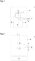
- FIGs 1 and 2 show exemplary embodiments of an optical sensor 1, which can be used for the monitoring device 12 according to the invention as in figure 3 shown as an example, is used.
- the Figures 1 and 2 12 show exemplary embodiments of distance-measuring optical sensors 1, the distance measurements advantageously being carried out using a pulse propagation time method or a phase measuring method.
- figure 1 1 shows an exemplary embodiment of an optical sensor 1 in the form of a surface distance sensor, ie a scanning distance sensor.
- the optical sensor 1 has a transmitter 3 emitting light beams 2 and a receiver 4 receiving light beams 2 .
- the transmitter 3 emits light beams 2 in the form of light pulses.
- the light beams 2 are reflected on an object 5 to be detected, with the corresponding light propagation time of the light pulses to the object 5 and back to the optical sensor 1 being evaluated for determining the distance.
- the sensor components of the optical sensors 1 are integrated in a housing 6 , with the transmitter 3 and the receiver 4 being arranged in the housing 6 in a stationary manner with an upstream optical receiving system 7 .
- an object is detected in a flat detection area in that the light beams 2 are deflected by means of a deflection unit 8 be periodically distracted.
- the deflection unit 8 is motor-driven and includes an angle mirror 9 which can be rotated about an axis of rotation D and on which the light beams 2 are deflected.
- FIG figure 2 shows a variant of the area distance sensor according to FIG figure 1 .
- the periodic deflection of the light beams 2 takes place in that the transmitter 3 and the receiver 4 are arranged in a measuring head 10 that can be rotated about an axis of rotation D, with the measuring head 10 being rotatably mounted on a base 11 .
- each optical sensor 1 is assigned an evaluation unit (not shown), in which the received signals of the receiver 4 are evaluated.
- the optical sensors 1 are according to Figures 1 and 2 designed as a safety sensor and have a fail-safe design, which can be implemented, for example, by a redundant evaluation unit in the form of two computer units that cyclically monitor one another.
- FIG. 3 shows an exemplary embodiment of the monitoring device 12 according to the invention with an optical sensor 1 as in FIGS Figures 1 and 2 described.
- the optical sensor 1 is located on the front side of a driverless transport vehicle 13 which is controlled by a safe controller 14.
- a safe controller 14 instead of the driverless transport vehicle 13, another mobile machine can also be provided, which in particular can be guided by rails.
- the safe controller 14 also assumes the function of the evaluation unit of the optical sensor 1 and for this purpose is connected to the optical sensor 1 via an interface, for example a field bus, in order to exchange data bidirectionally. The exchange of data between the optical sensor 1 and the controller 14 also takes place securely, for example via a secure fieldbus.
- the interface between the sensor and the safe controller can consist of several lines that transmit digital signals.
- the protective field 15 is designed as a surface area which covers the area in front of the driverless transport vehicle 13 .
- the protective field is monitored in such a way that, depending on an object intrusion in a protective field 15, a binary switching signal is generated whose switching states indicate whether an object 5 is present in the protective field 15 or not. If an object 5 is present in the protective field 15, a safety function is triggered by the corresponding switching state of the switching signal in such a way that a dangerous machine is stopped so that no more dangers can emanate from it. In the present case, the safety function consists in stopping driverless transport vehicle 13 .
- contour detection fields K1, K2, K3 are also monitored with the optical sensor 1.
- the protective field 15 is adjusted based on the monitoring of the contour detection fields K1 , K2 , K3 while the driverless transport vehicle 13 is moving toward a wall 16 as a stationary obstacle or is moving away from the wall 16 .
- the size of the protective field 15 is generally adjusted in such a way that the protective field 15 covers the area between the driverless transport vehicle 13 and the wall 16 as completely as possible.
- contour detection fields K1, K2, K3 form strip-shaped, elongated, flat areas that extend beyond the front edge of the protective field 15 and do not overlap there.
- all contour detection fields K1, K2, K3 have different lengths.
- the longest contour detection field K1 is in the middle in front of the driverless transport vehicle 13 is provided.
- the longitudinal axis of the contour detection field K1 runs along the longitudinal axis of the driverless transport vehicle. 13.
- the shorter contour detection fields K2, K3 are arranged on both sides of the first contour detection field K1 and extend laterally beyond the edges of the driverless transport vehicle 13.
- the minimum distance between the contour detection fields K2, K3 outside the protective field 15 is denoted by a. This is selected to be large enough that a person cannot penetrate into these contour detection fields at the same time, even with spread legs or arms. Typically, the minimum distance a is greater than 700 mm.
- the contour detection fields K1, K2, K3 each have two occupancy states, namely the occupancy state "occupied” when an object 5 is present in the respective contour detection field, and the occupancy state "free” if no object 5 is present in the respective contour detection field.
- the evaluation unit increases or decreases the protective field 15 depending on sequences of occupancy states registered with the optical sensor 1, in particular occupancy state changes of the three contour detection fields K1, K2, K3.
- the protective field 15 is only reduced if the contour detection fields K1, K2, K3 are occupied one after the other in a predetermined sequence.
- the driverless transport vehicle 13 approaches the wall 16, this is considered to be detected when the middle contour detection field K1 is occupied first, then the second longest contour detection field K3 is occupied and finally the shortest contour detection field K2 is occupied.
- the protective field 15 is then reduced in size in such a way that the wall 16 lies outside the protective field 15 so that a safety function is not generated unnecessarily by this.
- the protective field 15 is enlarged when all contour detection fields K1, K2, K3 become free.
- the protective field 15 is enlarged when the longest contour detection field K1 becomes free.
- the one or more free contour detection fields signal a free area in front, which allows an enlargement of the protective field 15 without a stationary obstacle being present in it.
- a time monitoring unit is expediently provided, which is advantageously integrated in the evaluation unit. This is used to check the duration of the sequences of occupancy states, which can lead to an increase or decrease in the protective field 15 .
- the time monitoring unit checks whether a sequence exceeds a certain minimum duration, which is a criterion for a valid sequence, in particular for reducing the protective field 15 .
Landscapes
- Physics & Mathematics (AREA)
- Engineering & Computer Science (AREA)
- Electromagnetism (AREA)
- Computer Networks & Wireless Communication (AREA)
- General Physics & Mathematics (AREA)
- Radar, Positioning & Navigation (AREA)
- Remote Sensing (AREA)
- General Engineering & Computer Science (AREA)
- Mechanical Engineering (AREA)
- Optical Radar Systems And Details Thereof (AREA)
Claims (18)
- Dispositif de surveillance (12) doté d'un capteur optique (1), permettant de surveiller un objet à l'intérieur d'un champ de protection (15), dans lequel trois champs de détection de contour (Kl, K2, K3) de longueurs différentes sont prévus, dans lequel les champs de détection de contour (Kl, K2, K3) dépassent le champ de protection (15) et ne s'y chevauchent pas, au moins partiellement, et dans lequel un agrandissement ou une réduction du champ de protection (15) est effectué en fonction de la séquence des états d'occupation des champs de détection de contour (Kl, K2, K3), au moins partiellement, et dans laquelle un élargissement ou une réduction du champ de protection (15) est effectué en fonction de la séquence des états d'occupation des zones de détection de contour (Kl, K2, K3), caractérisé par le fait que la zone de détection de contour la plus longue (Kl) est disposée entre les deux autres zones de détection de contour.
- Dispositif de surveillance (12) selon la revendication 1, caractérisé par le fait que le capteur optique (1) est placé sur une machine mobile de manière à ce que le tablier de la machine mobile soit surveillé par le champ de protection (15).
- Dispositif de surveillance (12) selon la revendication 2, caractérisé par le fait qu'une zone de détection de contour (Kl) est prévue au centre devant la machine mobile et que les autres zones de détection de contour (K2, K3) dépassent latéralement de la machine mobile.
- Dispositif de surveillance (12) selon l'une des revendications 1 à 3, caractérisé par le fait que la distance minimale entre les segments des deux champs de détection de contours extérieurs (K2, K3) faisant saillie sur le champ de protection (15) est si grande qu'ils ne peuvent pas être occupés simultanément par une personne.
- Dispositif de surveillance (12) selon l'une des revendications 1 à 4, caractérisé par le fait que le champ de protection (15) n'est réduit que si les champs de détection de contour (K1, K2, K3) sont occupés l'un après l'autre dans un ordre prédéterminé.
- Dispositif de surveillance (12) selon l'une des revendications 1 à 5, caractérisé en ce que le champ de protection (15) est agrandi lorsque toutes les zones de détection de contour (Kl, K2, K3) sont libres.
- Dispositif de surveillance (12) selon l'une des revendications 1 à 5, caractérisé en ce que le champ de protection (15) est élargi lorsque le champ de détection de contour le plus long (Kl) devient libre.
- Dispositif de surveillance (12) selon l'une des revendications 1 à 7, caractérisé en ce qu'une unité de surveillance du temps est prévue, au moyen de laquelle la durée d'une séquence d'états d'occupation est contrôlée.
- Dispositif de surveillance (12) selon la revendication 8, caractérisé en ce qu'une séquence valide pour le changement de champ de protection est présente si sa durée dépasse une durée minimale prédéterminée.
- Dispositif de surveillance (12) selon l'une des revendications 1 à 9, caractérisé en ce que le capteur optique (1) est un capteur de distance.
- Dispositif de surveillance (12) selon l'une des revendications 1 à 10, caractérisé par le fait que le champ de protection (15) et les champs de reconnaissance des contours (K1, K2, K3) forment des zones bidimensionnelles ou tridimensionnelles.
- Dispositif de surveillance (12) selon l'une des revendications 1 à 5, caractérisé en ce que les champs de détection des contours (Kl, K2, K3) sont conçus sous forme de bandes.
- Dispositif de surveillance (12) selon l'une des revendications 1 à 12, caractérisé en ce que le capteur optique (1) possède une unité d'évaluation ou en ce qu'une unité d'évaluation externe est affectée au capteur optique (1).
- Dispositif de surveillance (12) selon la revendication 13, caractérisé en ce que l'unité d'évaluation externe est un contrôleur de sécurité (14) qui est connecté au capteur optique (1) via une interface.
- Dispositif de surveillance (12) selon l'une des revendications 13 ou 14, caractérisé par le fait qu'un signal de commutation est généré dans l'unité d'évaluation en fonction des signaux du capteur optique (1), dont les états de commutation indiquent si un objet (5) se trouve ou non dans le champ de protection (15).
- Dispositif de surveillance (12) selon la revendication 15, caractérisé par le fait qu'une fonction de sécurité est déclenchée lorsqu'un objet est détecté dans le champ de protection (15).
- Dispositif de surveillance (12) selon l'une des revendications 2 à 16, caractérisé par le fait que la machine mobile est un véhicule guidé par rail.
- Procédé d'utilisation d'un dispositif de surveillance (12) doté d'un capteur optique (1), permettant de surveiller un objet dans un champ de protection (15), dans lequel trois champs de détection de contour (Kl, K2, K3) de longueurs différentes sont prévus, dans lequel les champs de détection de contour (Kl, K2, K3) dépassent le champ de protection (15) et ne s'y chevauchent pas au moins partiellement, et
un élargissement ou une réduction de la zone de protection (15) est effectué en fonction de la séquence des états d'occupation des zones de détection de contour, caractérisé par le fait que la zone de détection de contour la plus longue (Kl) est disposée entre les deux autres zones de détection de contour.
Priority Applications (1)
| Application Number | Priority Date | Filing Date | Title |
|---|---|---|---|
| EP21186165.3A EP4119982B1 (fr) | 2021-07-16 | 2021-07-16 | Dispositif de surveillance et procédé de fonctionnement d'un dispositif de surveillance |
Applications Claiming Priority (1)
| Application Number | Priority Date | Filing Date | Title |
|---|---|---|---|
| EP21186165.3A EP4119982B1 (fr) | 2021-07-16 | 2021-07-16 | Dispositif de surveillance et procédé de fonctionnement d'un dispositif de surveillance |
Publications (2)
| Publication Number | Publication Date |
|---|---|
| EP4119982A1 EP4119982A1 (fr) | 2023-01-18 |
| EP4119982B1 true EP4119982B1 (fr) | 2023-06-07 |
Family
ID=76958846
Family Applications (1)
| Application Number | Title | Priority Date | Filing Date |
|---|---|---|---|
| EP21186165.3A Active EP4119982B1 (fr) | 2021-07-16 | 2021-07-16 | Dispositif de surveillance et procédé de fonctionnement d'un dispositif de surveillance |
Country Status (1)
| Country | Link |
|---|---|
| EP (1) | EP4119982B1 (fr) |
Family Cites Families (3)
| Publication number | Priority date | Publication date | Assignee | Title |
|---|---|---|---|---|
| DE102016125595B4 (de) * | 2016-12-23 | 2019-09-12 | Sick Ag | Zugangsabsicherungssystem |
| EP3882505B1 (fr) * | 2020-03-16 | 2024-03-13 | Leuze electronic GmbH + Co. KG | Dispositif de surveillance et procédé de fonctionnement d'un dispositif de surveillance |
| DE202020103157U1 (de) * | 2020-06-02 | 2021-02-09 | Leuze Electronic Gmbh + Co. Kg | Überwachungseinrichtung |
-
2021
- 2021-07-16 EP EP21186165.3A patent/EP4119982B1/fr active Active
Also Published As
| Publication number | Publication date |
|---|---|
| EP4119982A1 (fr) | 2023-01-18 |
Similar Documents
| Publication | Publication Date | Title |
|---|---|---|
| EP3339715B1 (fr) | Système de protection d'accès | |
| EP2470407B1 (fr) | Dispositif de surveillance et procédé de surveillance d'une zone d'entrée ou de sortie d'une ouverture d'accès d'un véhicule à une partie d'un édifice | |
| EP1494048B1 (fr) | Rideau de lumière | |
| EP2306063B1 (fr) | Capteur de sécurité | |
| EP3587894B1 (fr) | Agencement de capteurs et procédé de fonctionnement d'un agencement de capteurs | |
| DE10312972B3 (de) | Optischer Sensor | |
| EP3882505B1 (fr) | Dispositif de surveillance et procédé de fonctionnement d'un dispositif de surveillance | |
| EP3415804B1 (fr) | Dispositif de sécurité | |
| EP3217195B1 (fr) | Capteur optique | |
| DE102016116828B4 (de) | Sicherheitslichtvorhang | |
| EP2395372B1 (fr) | Scanner de sécurité | |
| EP4119982B1 (fr) | Dispositif de surveillance et procédé de fonctionnement d'un dispositif de surveillance | |
| EP3919801B1 (fr) | Dispositif de surveillance | |
| EP3671289B1 (fr) | Système de détection | |
| EP3640522B1 (fr) | Dispositif de surveillance | |
| EP3862617B1 (fr) | Dispositif de sécurisation d'une zone dangereuse | |
| EP3627033B1 (fr) | Dispositif de sécurisation d'une zone à risque d'une installation | |
| EP3640521B1 (fr) | Dispositif de surveillance | |
| EP3869240B1 (fr) | Agencement de capteurs et procédé de fonctionnement d'un agencement de capteurs | |
| EP3770708A1 (fr) | Dispositif de surveillance | |
| EP3757443B1 (fr) | Élément de surveillance et procédé de sécurisation de zones dangereuses | |
| EP3945238B1 (fr) | Dispositif de surveillance et procédé de fonctionnement d'un dispositif de surveillance | |
| DE202022105448U1 (de) | Überwachungseinrichtung | |
| EP3770481B1 (fr) | Dispositif capteur et procédés de surveillance de zone dangereuse | |
| EP4614054A1 (fr) | Dispositif de surveillance et procédé de fonctionnement d'un dispositif de surveillance |
Legal Events
| Date | Code | Title | Description |
|---|---|---|---|
| STAA | Information on the status of an ep patent application or granted ep patent |
Free format text: STATUS: EXAMINATION IS IN PROGRESS |
|
| PUAI | Public reference made under article 153(3) epc to a published international application that has entered the european phase |
Free format text: ORIGINAL CODE: 0009012 |
|
| 17P | Request for examination filed |
Effective date: 20220308 |
|
| AK | Designated contracting states |
Kind code of ref document: A1 Designated state(s): AL AT BE BG CH CY CZ DE DK EE ES FI FR GB GR HR HU IE IS IT LI LT LU LV MC MK MT NL NO PL PT RO RS SE SI SK SM TR |
|
| RIC1 | Information provided on ipc code assigned before grant |
Ipc: G01S 17/931 20200101ALI20230125BHEP Ipc: G01S 17/10 20060101ALI20230125BHEP Ipc: F16P 3/14 20060101ALI20230125BHEP Ipc: G01S 17/04 20200101AFI20230125BHEP |
|
| GRAP | Despatch of communication of intention to grant a patent |
Free format text: ORIGINAL CODE: EPIDOSNIGR1 |
|
| STAA | Information on the status of an ep patent application or granted ep patent |
Free format text: STATUS: GRANT OF PATENT IS INTENDED |
|
| INTG | Intention to grant announced |
Effective date: 20230307 |
|
| GRAS | Grant fee paid |
Free format text: ORIGINAL CODE: EPIDOSNIGR3 |
|
| GRAA | (expected) grant |
Free format text: ORIGINAL CODE: 0009210 |
|
| STAA | Information on the status of an ep patent application or granted ep patent |
Free format text: STATUS: THE PATENT HAS BEEN GRANTED |
|
| RBV | Designated contracting states (corrected) |
Designated state(s): DE |
|
| AK | Designated contracting states |
Kind code of ref document: B1 Designated state(s): DE |
|
| REG | Reference to a national code |
Ref country code: DE Ref legal event code: R096 Ref document number: 502021000790 Country of ref document: DE |
|
| P01 | Opt-out of the competence of the unified patent court (upc) registered |
Effective date: 20230606 |
|
| REG | Reference to a national code |
Ref country code: DE Ref legal event code: R097 Ref document number: 502021000790 Country of ref document: DE |
|
| PLBE | No opposition filed within time limit |
Free format text: ORIGINAL CODE: 0009261 |
|
| STAA | Information on the status of an ep patent application or granted ep patent |
Free format text: STATUS: NO OPPOSITION FILED WITHIN TIME LIMIT |
|
| 26N | No opposition filed |
Effective date: 20240308 |
|
| PGFP | Annual fee paid to national office [announced via postgrant information from national office to epo] |
Ref country code: DE Payment date: 20250722 Year of fee payment: 5 |