EP4120198A1 - Format d'image de surface multi-objets (mosi) - Google Patents
Format d'image de surface multi-objets (mosi) Download PDFInfo
- Publication number
- EP4120198A1 EP4120198A1 EP21185484.9A EP21185484A EP4120198A1 EP 4120198 A1 EP4120198 A1 EP 4120198A1 EP 21185484 A EP21185484 A EP 21185484A EP 4120198 A1 EP4120198 A1 EP 4120198A1
- Authority
- EP
- European Patent Office
- Prior art keywords
- layers
- stack
- scene
- data
- objects
- Prior art date
- Legal status (The legal status is an assumption and is not a legal conclusion. Google has not performed a legal analysis and makes no representation as to the accuracy of the status listed.)
- Withdrawn
Links
Images


Classifications
-
- G—PHYSICS
- G06—COMPUTING OR CALCULATING; COUNTING
- G06T—IMAGE DATA PROCESSING OR GENERATION, IN GENERAL
- G06T15/00—Three-dimensional [3D] image rendering
- G06T15/10—Geometric effects
- G06T15/20—Perspective computation
-
- G—PHYSICS
- G06—COMPUTING OR CALCULATING; COUNTING
- G06T—IMAGE DATA PROCESSING OR GENERATION, IN GENERAL
- G06T15/00—Three-dimensional [3D] image rendering
- G06T15/10—Geometric effects
- G06T15/20—Perspective computation
- G06T15/205—Image-based rendering
-
- G—PHYSICS
- G06—COMPUTING OR CALCULATING; COUNTING
- G06T—IMAGE DATA PROCESSING OR GENERATION, IN GENERAL
- G06T15/00—Three-dimensional [3D] image rendering
- G06T15/04—Texture mapping
-
- G—PHYSICS
- G06—COMPUTING OR CALCULATING; COUNTING
- G06T—IMAGE DATA PROCESSING OR GENERATION, IN GENERAL
- G06T19/00—Manipulating three-dimensional [3D] models or images for computer graphics
- G06T19/20—Editing of three-dimensional [3D] images, e.g. changing shapes or colours, aligning objects or positioning parts
-
- G—PHYSICS
- G06—COMPUTING OR CALCULATING; COUNTING
- G06T—IMAGE DATA PROCESSING OR GENERATION, IN GENERAL
- G06T7/00—Image analysis
- G06T7/50—Depth or shape recovery
- G06T7/55—Depth or shape recovery from multiple images
-
- G—PHYSICS
- G06—COMPUTING OR CALCULATING; COUNTING
- G06T—IMAGE DATA PROCESSING OR GENERATION, IN GENERAL
- G06T7/00—Image analysis
- G06T7/70—Determining position or orientation of objects or cameras
-
- H—ELECTRICITY
- H04—ELECTRIC COMMUNICATION TECHNIQUE
- H04N—PICTORIAL COMMUNICATION, e.g. TELEVISION
- H04N13/00—Stereoscopic video systems; Multi-view video systems; Details thereof
- H04N13/20—Image signal generators
- H04N13/271—Image signal generators wherein the generated image signals comprise depth maps or disparity maps
-
- H—ELECTRICITY
- H04—ELECTRIC COMMUNICATION TECHNIQUE
- H04N—PICTORIAL COMMUNICATION, e.g. TELEVISION
- H04N13/00—Stereoscopic video systems; Multi-view video systems; Details thereof
- H04N13/20—Image signal generators
- H04N13/282—Image signal generators for generating image signals corresponding to three or more geometrical viewpoints, e.g. multi-view systems
-
- G—PHYSICS
- G06—COMPUTING OR CALCULATING; COUNTING
- G06T—IMAGE DATA PROCESSING OR GENERATION, IN GENERAL
- G06T2207/00—Indexing scheme for image analysis or image enhancement
- G06T2207/20—Special algorithmic details
- G06T2207/20212—Image combination
- G06T2207/20224—Image subtraction
-
- G—PHYSICS
- G06—COMPUTING OR CALCULATING; COUNTING
- G06T—IMAGE DATA PROCESSING OR GENERATION, IN GENERAL
- G06T2210/00—Indexing scheme for image generation or computer graphics
- G06T2210/62—Semi-transparency
-
- H—ELECTRICITY
- H04—ELECTRIC COMMUNICATION TECHNIQUE
- H04N—PICTORIAL COMMUNICATION, e.g. TELEVISION
- H04N2213/00—Details of stereoscopic systems
- H04N2213/005—Aspects relating to the "3D+depth" image format
Definitions
- the invention relates to the field of multi-view image formats.
- the invention relates to the processing and rendering of a format for multi-view image frame data.
- Multi Plane Image and Multi Sphere Image (MSI) techniques construct color and transparency for a predefined set of planes or spheres in 3D space. For a new virtual viewpoint, the image is then constructed using back-to-front over-compositing of the layers.
- MPI and MSI have become popular as 3D image formats for representing multi-view video.
- the MPI and MSI formats consists of multiple colored images with transparency positioned at varying depth (planes) or distances (spheres) from a point.
- the colored layers are shifted with respect to each other and the colors are then composited together.
- the MPI and MSI formats seem suitable for representing multi-view video, some problems remain.
- the formats typically consist of many (> 100) frame size RGBA (i.e. color and transparency) depth layers thereby automatically expanding the original multi-view captured pixel data related size rather than reducing the pixel data related size.
- RGBA i.e. color and transparency
- Both MPI and MSI formats place layers at pre-determined and fixed positions irrespective of the observed scene. Moreover, these layers are typically spread out in a uniform fashion over space (sometimes denser close to the capture system than further away from the capture system). In practice, the placement of layers everywhere is likely to cause the introduction of ghost objects. For instance, recent works show that MPI is over-parameterized for real scenes that consist of large areas of empty space. The suggested solution for this problem is enforcing sparsity on the layers. However, enforcing sparsity on the layers may reduce the visual quality of objects in the scene.
- a method for processing multi-view image data comprising:
- layered approaches to multi-view images use layers (planes) spaced out in the virtual scene.
- the spacing of the layers is usually constant or based on the distance from a target viewpoint.
- the inventors have realized that these formats use a large amount of data to store and transmit and thus may not always be suitable (e.g. particularly for real-time broadcasting). For example, most layers would have a significant number of pixels with 100% transparency and would thus not contain any useful data of any of the objects whilst still having to be stored.
- the inventors propose generating a stack of layers for each object but having the stack of layers positioned in the virtual scene where the object would be in the scene.
- layers are mostly positioned by (or near) objects and the number of pixels with 100% transparency can be significantly reduced. This is possible from obtaining the positions of the objects in the scene.
- the positions of the objects could be obtained from a segmentation of the source texture data and/or the source depth data. Trained machine learning algorithms could also be used to detect the positions of the objects. Other methods for obtaining the positions of the objects will be known to a person skilled in the art. For example, in a soccer match, the position of the soccer field and the stadium could be obtained from a user-generated 3D model and the position of the players and the ball could be obtained from object detection algorithms.
- the objects could be generated in a scene by a graphics engine and the position of the object would thus be known from where the object was generated in the scene by the graphics engine.
- the position of a stack of layers could be defined, for example, by a 3D coordinate defining the center of the stack of layers and the size and/or geometry of the stack.
- the position of a stack of layers can be defined by an arbitrary pixel of an arbitrary layer in the stack of layers, the number of layers and the spacing of the layers.
- Each pixel in a layer could have an RGBA (i.e. color and transparency).
- Some thin or semi-transparent objects may be better represented (i.e. resulting in higher image quality) as transparent layers than as a textured mesh or a blend of multiple warped textures from a multi-view with depth format. This could then result in an overall system where the different formats (e.g. mesh, multi-view with depth and MOSI) are spatially combined to describe a scene.
- the different formats e.g. mesh, multi-view with depth and MOSI
- the relevant texture/depth map and alpha map data may be packed together in a single video file for transmission.
- the metadata could indicate what is where in the packed video texture atlas.
- the particular format relating to the stacks of layers representing objects in their respective positions may be referred to as the Multi Object Surface Imaging (MOSI) format.
- MOSI Multi Object Surface Imaging
- the orientation of the stack of layers in the virtual scene may be based on one or more of: the position of the corresponding object in the scene, the orientation of the corresponding object in the scene, the geometry of the corresponding object, a-priori knowledge of the corresponding object, the position of one or more of the plurality of sensors, the orientation of one or more of the plurality of sensors and the position of an intended viewing zone.
- the orientation of the object could be measured from the source view data (i.e. position, orientation and/or geometry of object).
- the layers in the stack may be generated parallel (or close to parallel) to an axis defined by the elongated object.
- the orientation of an object may already be known.
- the orientation of a soccer field will always be known from any viewpoint as it does not change.
- the position, geometry and orientation of the object (or sensors) could be obtained from the graphics engine.
- the plane orientations may be selected such that they have their normal parallel to the mean viewing direction of a viewing zone.
- the intended viewing zone may be in a six degrees of freedom (6DoF) region (i.e. position and orientation) in which a viewer is supposed to move (and get acceptable image quality). It relates to the sensor capture configuration which is designed to capture a given viewing zone (i.e. dependent on the number of cameras, field-of-view, position/orientation).
- 6DoF degrees of freedom
- the shape of the layers corresponding to a stack of layers may be based on one or more of: the position of the corresponding object in the scene, the orientation of the corresponding object in the scene, the geometry of the corresponding object and a-priori knowledge of the corresponding object.
- the shape of the stack of layers may be spherical, cylindrical or rectangular for example.
- the shape of the stack may be based on the shape of the layers which make up the stack.
- the layers may be a cylindrical shell, a spherical shell or a plane depending on the shape of the corresponding stack of layers. For example, a soccer ball may benefit from spherical layers in the corresponding stack whereas a soccer field may benefit from planar layers in the corresponding stack.
- the shape of the layers could consist of shrunk or expanded object surfaces where these have shrunk or expanded along the normal vector of the true surface geometry.
- a graphics engine render/export script could then generate the MOSI format for the object.
- Obtaining the position of one or more objects in the scene may be based on obtaining a background model of the scene containing background depth data of the background of the scene, thereby containing the position of the background, subtracting the background depth data from the source depth data, detecting foreground objects in the subtracted data and determining a position of the foreground objects in the virtual scene, wherein the position of the objects is based on the position of the background and the position of the foreground objects.
- the method may further comprise generating one or more additional stacks of layers for one or more of the objects thereby to make the objects fully visible when viewed from any point in a target viewing space using at least one of the stack of layers or the additional stacks of layers, wherein an additional stack of layers for a first object has a different orientation to the stack of the layers for the first object and wherein a target viewing space defines a sub-space in the virtual scene from which a viewer can view the virtual scene.
- rendering the texture data of the layers may create artefacts which may prevent the object from being fully visible when viewed from certain angles. For example, if planar layers are viewed from an axis parallel to the planar layers, the full texture data of the layers might not be visible to the viewer. Similarly, if a cylindrical layer is viewed from above the texture data might not be fully visible.
- a target viewing space can be defined from which a viewer could view the virtual scene.
- additional stacks of layers can be generated for the corresponding object (e.g. different orientation and/or shape) such that the object will always be visible without artefacts within the target viewing space.
- An additional stack of layers will have a different orientation to the "original" stack of layers for the same objects.
- the layers in the additional stack of layers may be orthogonal or almost orthogonal (e.g. between 70 and 110 degrees) to the layers in the stack of layers.
- a first stack of layers may be generated such that the layers in the first stack of layers intersect the layers in a second stack of layers.
- a stack of layers representing a soccer player is not intersecting a stack of layers representing a soccer field, when the virtual scene is viewed from certain angles the soccer player may look like he is floating above the soccer field. Thus, intersecting both stacks of layers ensures the virtual scene does not look "unnatural".
- the sections of the layers which intersect may, for example, be blended when being rendered.
- the method may further comprise receiving a data allocation for each known object in a set of known objects and storing the layers in a stack of layers for the known object at a first resolution and/or first frame rate based on the data allocation for the known object.
- each frame there is typically a limit to the size of each frame based on the type of network used for broadcasting (e.g. 4G, 5G etc.).
- a data allocation can be given to each object in order to ensure that all objects can fit within the limit of the network.
- each layer for a background object can be stored in an 8k frame with a relatively low frame rate (e.g. 10 fps) whereas a foreground object (e.g. soccer ball) can be stored in a 4k frame with a relatively high frame rate (e.g. 30 fps).
- a relatively low frame rate e.g. 10 fps
- a foreground object e.g. soccer ball
- the method may further comprise generating metadata for the stacks of layers, the metadata containing one or more of: the position of the stack of layers, the orientation of the stack of layers, the number of layers in the stack of layers, the spacing between layers, the type and/or shape of the layers and the dynamics of the stack of layers.
- the spacing between layers may be a function of the position of the stack of layers.
- the dynamics of a stack of layers refers to any temporal coding of the stack.
- the global position or orientation of the stack of layers may change over time.
- the spacing of the stack or number of layers in the stack may change over time when, for example, an object moves further away from the average viewing position and thus less look-around effect needs to be modelled.
- the source texture data may comprise a plurality of source view images and wherein generating the texture data and transparency data for a layer is based on the texture data from the source view images.
- generating the texture data and transparency data comprises projecting each source view image onto the virtual scene, wherein each source pixel in the source view image has a corresponding position in the virtual scene. For each one of the layers, it further comprises determining for each source pixel in each source view image: a proximal pixel being the pixel in the layer closest to the source pixel in the virtual scene, a source to layer distance between the proximal pixel and the source pixel, and a weight based on the source to layer distance.
- a target color value can be generated for each layer pixel in the layer based on the weights corresponding to the layer pixel and a source color value of each one of the source pixels used to find the source to layer distances for the corresponding layer pixel.
- the weight may be determined based on the angle between a vector from the source camera to the source pixel and a vector that lies orthogonal to the target plane and intersects it in the target pixel (i.e. the target plane essentially corresponds with a parallel projection instead of a perspective projection).
- Finding the texture and transparency data for a layer can be done for each pixel in the layer based on the source view images.
- Each source view image is projected onto the virtual scene and the closest pixel in a layer (i.e. proximal pixel) to each pixel of each source view image is found (i.e. source pixels).
- the distance between a source pixel and the corresponding proximal layer pixel gives an estimate of the importance/weight of the source pixel's contribution to the layer pixel. For example, the source pixels which are far from the layer are less likely to contain a color value relevant to a pixel for the layer whereas closer source pixels are likely to be more relevant.
- the distance (i.e. source to layer distance) between a source pixel and the corresponding proximal pixel in a given layer can be used to determine a weight.
- the weight can then be used to generate a target color value for the target pixel by, for example, weighting the color of each source pixel with the corresponding weight and finding the sum of the weighted source color values.
- the source view pixel with the highest weight value is used for the color of the layer pixel.
- Other alternative sampling schemes may also be adopted.
- the source view data may comprise texture images of the scene and the source texture data and the source depth data may be obtained by performing depth estimation on the texture images.
- the invention also provides a method for rendering multi-view image data depicting a scene with one or more objects, the method comprising:
- the method may further comprise sorting the stacks of layers based on the distance between the position of the stacks of layers and the position of the target viewpoint in the virtual scene.
- Rendering the stacks of layers may be performed in decreasing order of the distance from each stack of layers to the target viewpoint and wherein rendering the layers in each stack of layers is in decreasing order based on the distance between the position of each layer and the position of the target viewpoint.
- the invention also provides a computer program product comprising computer program code means which, when executed on a computing device having a processing system, cause the processing system to perform all of the steps of the afore-mentioned methods of processing and rendering multi-view data.
- a processor is also provided to execute the code.
- the invention also provides a bitstream containing multi-view image frame data depicting a scene with one or more objects, the bitstream comprising a video bitstream, wherein the video bitstream includes a stack of layers in a virtual scene for at least one of the a subset of all objects in the scene and wherein:
- the invention provides a method for processing multi-view image data.
- the method comprises obtaining source view data from a plurality of sensors, the source view data containing source texture data and source depth data of a scene with one or more objects.
- the positions of one or more of the objects in the scene are obtained and a stack of layers is generated in a virtual scene for at least one of the objects, wherein the position of a stack of layers in the virtual scene is based on the position of the corresponding object in the scene.
- Generating a stack of layers comprises generating a plurality of layers, wherein each layer comprises texture data and transparency data for the corresponding object.
- Fig. 1 shows an illustration of the MPI and MSI formats.
- Fig. 1 (a) shows an illustration of the layers 102 in an MPI format.
- the layers 102 are spaced out relative to how far away they are from the viewpoint 104.
- the layers 102 for MPI are planes parallel to each other containing RGBA (i.e. color and transparency) data for each pixel and the spacing between each layer 102 is defined with respect to the depth from the viewpoint (i.e. the z direction).
- RGBA i.e. color and transparency
- Fig. 1 (b) shows an illustration of the layers 102 in an MSI format. Similarly to the MPI format, the layers 102 are spaced out relative to how far away they are from the center viewpoint 106.
- the layers 102 are spherical in shape and with as center viewpoint 106, where the spacing of the layers 102 is defined relative to the radius (in the r direction) of the previous closer layer 102, for example.
- the layers 102 in Fig. 1 (a) and/or Fig. 1 (b) could have a constant or arbitrary spacing.
- Fig. 2 shows an illustration of the multi object surface image (MOSI) format.
- MOSI multi object surface image
- the background and ground stacks 202a and 202b are planar stacks with three layers 102 each.
- the number of layers 102 per stack 202 may depend on the processing systems used, and/or the intended use of the MOSI format. Three layers 102 are shown in Fig. 2 purely for illustrative purposes.
- the stack 202c corresponds to an object on the ground (e.g. soccer player on a soccer field) and is a cylindrical stack.
- the layers 102 in stack 202c are hollow cylinders.
- the stack 202d also corresponds to an object on the ground but the stack 202d is a planar stack where the layers 102 are planes.
- the choice of shape for the stacks 202 may depend on the position of the object in the scene and/geometry of the corresponding object.
- a stack 202 may have layers 202 with the shape of the surface of the object and thus the stack 202 would have the shape of the object.
- each stack of layers 202 is directly related to the geometry of the scene. In other words, the position of objects in a scene defines the position of the corresponding stack of layers 202 in a virtual scene.
- the invention proposes to produce multi object surface images (MOSI) for a set of objects in the scene.
- MOSI multi object surface images
- the proposed MOSI format concentrates 3D surfaces (planes, cylinders, spheres) in stacks of layers 202 around the position where objects are actually located. In this way, prior knowledge about the scene geometry is used.
- the MOSI format therefore adapts to the specific geometry of a captured scene.
- MOSI format is more compact in terms of pixel rate and ghost objects are unlikely to occur far away from scene elements. This more compact MOSI format may also be faster when synthesizing new views.
- MOSI CMOS image stabilization
- MPI and MSI formats it is proposed to store RGBA data for each pixel in the layers 102.
- the MOSI format creates multiple stacks of layers 202 that have different locations in space corresponding to a-priori known locations where objects are in the scene.
- a single layer 102 in MOSI also consists of color and transparency information.
- a stack 202 corresponds to a given object in 3D space.
- stacks 202 may be sorted based on their position relative to a viewpoint. Stacks 202 can then be drawn, one after the other, with decreasing depth order from the viewpoint.
- the following procedure describes a method for defining the geometric position of MOSI stacks 202 starting from captured multi-view images.
- the example is for a typical sports scene as captured from the side of the arena:
- the depth estimation step between views may be omitted when a separate laser scanner (or depth sensor) is added to the multi-camera setup to capture a 3D point cloud.
- the above algorithm will change in that the stacks of layers 202 will be placed at dense clusters of points in the point cloud which correlate to objects in the scene.
- the following steps can be used to create an RGBA texture for each layer 102 in all stacks 202 using the captured multi-view camera images (i.e. source views) as input:
- the weights w ij ( u , v ) may be calculated not (only) on the basis of depth difference but on the basis of a more fundamental color match error term that is calculated using the position of the surface j. More specifically, a 3D point that lies on surface j with corresponding texture coordinate ( u , v ) may be mapped to the source views to retrieve N i color values.
- the statistics of these color values can be used to calculate w ij ( u , v ). For instance, if for a given source view i, the color difference varies much from the mean of the retrieved color values, then the weight w ij (u, v ) is automatically set a relatively low value, the reason being that the 3D points x j is likely occluded in the source view j. Other statistics, such as color variance or a general histogram of colors may be used to determine w ij ( u , v ).
- ground truth may come from a graphics engine that can directly produce the MOSI format or a further render step may be taken to use the original source views themselves as ground truth.
- Static stacks 202 can be hand-tuned in an editor to place these relative to static scene objects such as such a sports ground, a goal or a stadium background.
- Fig. 3 shows two stacks of layers 202 intersecting. Artefacts may arise due to the stacks 202 not intersecting. Thus, it may be advantageous for the stacks 202 to be placed such that they overlap. The stacks 202 may intersect to avoid an object looking like it is floating on the ground.
- the ground surface of a soccer field may be rendered bottom to top using over-compositing and then a vertically oriented stack (e.g. soccer player) may be rendered back to front using over compositing.
- a vertically oriented stack e.g. soccer player
- This approach requires no special blending of layers.
- a slight intersection of the two stacks e.g. at least one pixel may be needed just to avoid gaps.
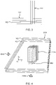
- Fig. 4 shows a scene with two stacks of layers 202 and an additional stack of layers 402.
- the additional stack of layers 402 may be identical to the stack of layers 202e but rotated by 90 degrees around the normal to the stack 202f.
- the stack 202f represents the ground in the scene and the stack 202e represents an object on the ground.
- the additional stack 402 represents the same object as 202e but the layers 102 have a different orientation from the layers 102 in stack 202e.
- MOSI stacks 202 may also be necessary to make some MOSI stacks 202 dependent on a target viewpoint 404.
- a target viewpoint 404 For instance, while the ground of a sport field represented by a planar stack may be suitable for viewing all around, this is not the case for a sports player when represented as a planar stack.
- Fig. 4 two target viewpoints 404a and 404b are shown.
- the stack 202e may be used to show the corresponding object in the scene.
- the stack 202e may not be suitable to show corresponding object (e.g. gaps between the layers 102 would be visible) but the additional stack 402 would be suitable.
- Additional stacks 402 may be generated for different target viewpoints 404 and/or based on a space within the scene from which a viewer can view the scene.
- Fig. 5 shows an example of a MOSI format where all the layers 102 are parallel.
- Fig. 5 shows an irregular layer 102 spacing that adapts to the position of objects 502.
- Stacks of layers 202 are placed at or near the depth of the objects 502.
- This form of the MOSI format is a modification of MPI that adapts to scene and object information. Variable layer spacing can be useful to account for uncertainties in an object detection process.
- the typical MOSI pixel data size (the total number of pixels summed over texture maps with each texture map corresponding to one layer 102) will be much less than what is needed for the MPI and MSI.
- the RGBA pixel values for the layers 102 in all stacks 202 still need to be packed into existing 2K, 4K or 8K frame sizes such that they can be compressed using a video encoder such as HEVC.
- a solution that has low computational cost is to define the packing format a-priori depending on the scene that is being imaged. For instance, for a soccer game, the stack 202 corresponding to the ground surface and the stack 202 corresponding to the stadium background may be packed into a single 4K video frame where a lower frame rate is used to reduce the temporal pixel rate.
- the soccer players on the other hand can be packed together into a second video where the texture size of the maximum number of players (e.g. 22) can vary such that players close to a target viewpoint can be packed with a higher resolution. Some space can be reserved for unforeseen objects that may enter the scene. Resolution scaling of the texture maps per stack 202 can be applied to always fit the result without losing objects. Note that the above reasoning can often also be applied to other dynamic events (e.g. other sport events).
- Metadata For a client device to correctly interpret the packed video, metadata which describes the geometric parameters of the MOSI stacks 202 may be needed in addition to the packing strategy that was used.
- the metadata for a single stack 202 may include one or more of:
- each step of a flow chart may represent a different action performed by a processor, and may be performed by a respective module of the processing processor.
- the system makes use of processor to perform the data processing.
- the processor can be implemented in numerous ways, with software and/or hardware, to perform the various functions required.
- the processor typically employs one or more microprocessors that may be programmed using software (e.g., microcode) to perform the required functions.
- the processor may be implemented as a combination of dedicated hardware to perform some functions and one or more programmed microprocessors and associated circuitry to perform other functions.
- circuitry examples include, but are not limited to, conventional microprocessors, application specific integrated circuits (ASICs), and field-programmable gate arrays (FPGAs).
- ASICs application specific integrated circuits
- FPGAs field-programmable gate arrays
- the processor may be associated with one or more storage media such as volatile and non-volatile computer memory such as RAM, PROM, EPROM, and EEPROM.
- the storage media may be encoded with one or more programs that, when executed on one or more processors and/or controllers, perform the required functions.
- Various storage media may be fixed within a processor or controller or may be transportable, such that the one or more programs stored thereon can be loaded into a processor.
- a single processor or other unit may fulfill the functions of several items recited in the claims.
- a computer program may be stored/distributed on a suitable medium, such as an optical storage medium or a solid-state medium supplied together with or as part of other hardware, but may also be distributed in other forms, such as via the Internet or other wired or wireless telecommunication systems.
- a suitable medium such as an optical storage medium or a solid-state medium supplied together with or as part of other hardware, but may also be distributed in other forms, such as via the Internet or other wired or wireless telecommunication systems.
Landscapes
- Engineering & Computer Science (AREA)
- Physics & Mathematics (AREA)
- Theoretical Computer Science (AREA)
- General Physics & Mathematics (AREA)
- Computer Graphics (AREA)
- Multimedia (AREA)
- Signal Processing (AREA)
- Computer Vision & Pattern Recognition (AREA)
- Computing Systems (AREA)
- Geometry (AREA)
- Architecture (AREA)
- Computer Hardware Design (AREA)
- General Engineering & Computer Science (AREA)
- Software Systems (AREA)
- Image Generation (AREA)
- Testing, Inspecting, Measuring Of Stereoscopic Televisions And Televisions (AREA)
Priority Applications (11)
| Application Number | Priority Date | Filing Date | Title |
|---|---|---|---|
| EP21185484.9A EP4120198A1 (fr) | 2021-07-14 | 2021-07-14 | Format d'image de surface multi-objets (mosi) |
| CN202280049479.0A CN117730346A (zh) | 2021-07-14 | 2022-07-12 | 多对象表面图像(mosi)格式 |
| JP2023578063A JP2024527269A (ja) | 2021-07-14 | 2022-07-12 | マルチオブジェクト表面画像(multi object surface image:mosi)フォーマット |
| EP22751022.9A EP4371077A1 (fr) | 2021-07-14 | 2022-07-12 | Format d'image de surface à objets multiples (mosi) |
| PCT/EP2022/069411 WO2023285435A1 (fr) | 2021-07-14 | 2022-07-12 | Format d'image de surface à objets multiples (mosi) |
| US18/578,032 US12488531B2 (en) | 2021-07-14 | 2022-07-12 | Multi object surface image (MOSI) format |
| MX2024000641A MX2024000641A (es) | 2021-07-14 | 2022-07-12 | Formato de imagen de superficie de objeto multiple (mosi). |
| CA3226416A CA3226416A1 (fr) | 2021-07-14 | 2022-07-12 | Format d'image de surface a objets multiples (mosi) |
| KR1020247005034A KR20240035554A (ko) | 2021-07-14 | 2022-07-12 | 다중 객체 표면 이미지(mosi) 포맷 |
| ARP220101834A AR126440A1 (es) | 2021-07-14 | 2022-07-13 | Formato de imagen de superficie de objeto múltiple (mosi) |
| TW111126388A TW202310616A (zh) | 2021-07-14 | 2022-07-14 | 多物件表面影像(mosi)格式 |
Applications Claiming Priority (1)
| Application Number | Priority Date | Filing Date | Title |
|---|---|---|---|
| EP21185484.9A EP4120198A1 (fr) | 2021-07-14 | 2021-07-14 | Format d'image de surface multi-objets (mosi) |
Publications (1)
| Publication Number | Publication Date |
|---|---|
| EP4120198A1 true EP4120198A1 (fr) | 2023-01-18 |
Family
ID=77021069
Family Applications (2)
| Application Number | Title | Priority Date | Filing Date |
|---|---|---|---|
| EP21185484.9A Withdrawn EP4120198A1 (fr) | 2021-07-14 | 2021-07-14 | Format d'image de surface multi-objets (mosi) |
| EP22751022.9A Pending EP4371077A1 (fr) | 2021-07-14 | 2022-07-12 | Format d'image de surface à objets multiples (mosi) |
Family Applications After (1)
| Application Number | Title | Priority Date | Filing Date |
|---|---|---|---|
| EP22751022.9A Pending EP4371077A1 (fr) | 2021-07-14 | 2022-07-12 | Format d'image de surface à objets multiples (mosi) |
Country Status (10)
| Country | Link |
|---|---|
| US (1) | US12488531B2 (fr) |
| EP (2) | EP4120198A1 (fr) |
| JP (1) | JP2024527269A (fr) |
| KR (1) | KR20240035554A (fr) |
| CN (1) | CN117730346A (fr) |
| AR (1) | AR126440A1 (fr) |
| CA (1) | CA3226416A1 (fr) |
| MX (1) | MX2024000641A (fr) |
| TW (1) | TW202310616A (fr) |
| WO (1) | WO2023285435A1 (fr) |
Citations (1)
| Publication number | Priority date | Publication date | Assignee | Title |
|---|---|---|---|---|
| JP2019046077A (ja) * | 2017-08-31 | 2019-03-22 | Kddi株式会社 | オブジェクト情報の複数面への投影によって視点映像を合成する映像合成装置、プログラム及び方法 |
Family Cites Families (8)
| Publication number | Priority date | Publication date | Assignee | Title |
|---|---|---|---|---|
| JP2000165641A (ja) * | 1998-11-24 | 2000-06-16 | Matsushita Electric Ind Co Ltd | 画像処理方法,画像処理装置およびデータ記憶媒体 |
| IL202460A (en) | 2009-12-01 | 2013-08-29 | Rafael Advanced Defense Sys | Method and system for creating a 3D view of real arena for military planning and operations |
| JP5866177B2 (ja) * | 2011-11-10 | 2016-02-17 | ソニー株式会社 | 画像処理装置および画像処理方法 |
| GB2499694B8 (en) | 2012-11-09 | 2017-06-07 | Sony Computer Entertainment Europe Ltd | System and method of image reconstruction |
| US10911732B2 (en) * | 2019-01-14 | 2021-02-02 | Fyusion, Inc. | Free-viewpoint photorealistic view synthesis from casually captured video |
| WO2021048276A1 (fr) | 2019-09-13 | 2021-03-18 | Interdigital Vc Holdings France, Sas | Procédés multi-échelle multi-vue et appareil pour la synthèse de vues |
| US11172148B2 (en) * | 2020-01-07 | 2021-11-09 | Google Llc | Methods, systems, and media for generating compressed images |
| US11601636B2 (en) * | 2020-05-22 | 2023-03-07 | Google Llc | Methods, systems, and media for generating an immersive light field video with a layered mesh representation |
-
2021
- 2021-07-14 EP EP21185484.9A patent/EP4120198A1/fr not_active Withdrawn
-
2022
- 2022-07-12 EP EP22751022.9A patent/EP4371077A1/fr active Pending
- 2022-07-12 CN CN202280049479.0A patent/CN117730346A/zh active Pending
- 2022-07-12 CA CA3226416A patent/CA3226416A1/fr active Pending
- 2022-07-12 JP JP2023578063A patent/JP2024527269A/ja active Pending
- 2022-07-12 KR KR1020247005034A patent/KR20240035554A/ko active Pending
- 2022-07-12 MX MX2024000641A patent/MX2024000641A/es unknown
- 2022-07-12 US US18/578,032 patent/US12488531B2/en active Active
- 2022-07-12 WO PCT/EP2022/069411 patent/WO2023285435A1/fr not_active Ceased
- 2022-07-13 AR ARP220101834A patent/AR126440A1/es unknown
- 2022-07-14 TW TW111126388A patent/TW202310616A/zh unknown
Patent Citations (1)
| Publication number | Priority date | Publication date | Assignee | Title |
|---|---|---|---|---|
| JP2019046077A (ja) * | 2017-08-31 | 2019-03-22 | Kddi株式会社 | オブジェクト情報の複数面への投影によって視点映像を合成する映像合成装置、プログラム及び方法 |
Non-Patent Citations (2)
| Title |
|---|
| ATTAL BENJAMIN ET AL: "MatryODShka: Real-time 6DoF Video View Synthesis Using Multi-sphere Images", 3 November 2020, INTELLIGENT ROBOTICS AND APPLICATIONS; [LECTURE NOTES IN COMPUTER SCIENCE; LECT.NOTES COMPUTER], PAGE(S) 441 - 459, ISBN: 978-3-030-89846-5, ISSN: 0302-9743, XP047593655 * |
| TINGHUI ZHOU ET AL: "Stereo Magnification: Learning View Synthesis using Multiplane Images", ARXIV.ORG, CORNELL UNIVERSITY LIBRARY, 201 OLIN LIBRARY CORNELL UNIVERSITY ITHACA, NY 14853, 24 May 2018 (2018-05-24), XP080882127 * |
Also Published As
| Publication number | Publication date |
|---|---|
| US12488531B2 (en) | 2025-12-02 |
| AR126440A1 (es) | 2023-10-11 |
| CN117730346A (zh) | 2024-03-19 |
| JP2024527269A (ja) | 2024-07-24 |
| US20240320900A1 (en) | 2024-09-26 |
| CA3226416A1 (fr) | 2023-01-19 |
| EP4371077A1 (fr) | 2024-05-22 |
| TW202310616A (zh) | 2023-03-01 |
| MX2024000641A (es) | 2024-02-06 |
| WO2023285435A1 (fr) | 2023-01-19 |
| KR20240035554A (ko) | 2024-03-15 |
Similar Documents
| Publication | Publication Date | Title |
|---|---|---|
| JP7277085B2 (ja) | 情報処理装置、情報処理方法及びプログラム | |
| KR20190034092A (ko) | 화상처리 장치, 화상처리 방법, 화상처리 시스템 및 기억매체 | |
| US20240378789A1 (en) | Depth segmentation in multi-view videos | |
| US10832468B2 (en) | Arbitrary view generation | |
| KR101168384B1 (ko) | 깊이 맵을 생성하는 방법, 깊이 맵 생성 유닛, 이미지 처리 장치, 및 컴퓨터 프로그램 제품 | |
| CA3210887A1 (fr) | Stockage et rendu d'ordres de profondeur pour trame multi-vues | |
| US7209136B2 (en) | Method and system for providing a volumetric representation of a three-dimensional object | |
| WO2023004559A1 (fr) | Vidéo de point de vue libre modifiable à l'aide d'une représentation neuronale en couches | |
| JP6799468B2 (ja) | 画像処理装置、画像処理方法及びコンピュータプログラム | |
| WO2020184174A1 (fr) | Dispositif de traitement d'image et procédé de traitement d'image | |
| Tomiyama et al. | Algorithm for dynamic 3D object generation from multi-viewpoint images | |
| US10163250B2 (en) | Arbitrary view generation | |
| US12488531B2 (en) | Multi object surface image (MOSI) format | |
| KR101163020B1 (ko) | 3차원 모델을 스케일링하는 방법 및 스케일링 유닛 | |
| Worchel et al. | Ernst Grube: A Contemporary Witness and His Memories Preserved with Volumetric Video. | |
| US20250363741A1 (en) | Depth rendering from neural radiance fields for 3d modeling | |
| Kunita et al. | Layered probability maps: basic framework and prototype system | |
| Huang et al. | Panoramic depth reconstruction within a single shot by optimizing global sphere radii | |
| KR20260009348A (ko) | 형상 의존적 신규 뷰 합성 | |
| Hentschke et al. | Generation of 3D Image Sequences from Mixed 2D and 3D Image Sources | |
| Palomo et al. | An efficient algorithm for depth image rendering | |
| Cheng et al. | An image inpainting method for stereoscopic images based on hole classification |
Legal Events
| Date | Code | Title | Description |
|---|---|---|---|
| PUAI | Public reference made under article 153(3) epc to a published international application that has entered the european phase |
Free format text: ORIGINAL CODE: 0009012 |
|
| STAA | Information on the status of an ep patent application or granted ep patent |
Free format text: STATUS: THE APPLICATION HAS BEEN PUBLISHED |
|
| AK | Designated contracting states |
Kind code of ref document: A1 Designated state(s): AL AT BE BG CH CY CZ DE DK EE ES FI FR GB GR HR HU IE IS IT LI LT LU LV MC MK MT NL NO PL PT RO RS SE SI SK SM TR |
|
| STAA | Information on the status of an ep patent application or granted ep patent |
Free format text: STATUS: THE APPLICATION IS DEEMED TO BE WITHDRAWN |
|
| 18D | Application deemed to be withdrawn |
Effective date: 20230719 |