EP4120441A1 - Batteriemodul und batteriepack damit - Google Patents
Batteriemodul und batteriepack damit Download PDFInfo
- Publication number
- EP4120441A1 EP4120441A1 EP21869540.1A EP21869540A EP4120441A1 EP 4120441 A1 EP4120441 A1 EP 4120441A1 EP 21869540 A EP21869540 A EP 21869540A EP 4120441 A1 EP4120441 A1 EP 4120441A1
- Authority
- EP
- European Patent Office
- Prior art keywords
- heat conductive
- conductive resin
- resin layer
- battery
- battery cell
- Prior art date
- Legal status (The legal status is an assumption and is not a legal conclusion. Google has not performed a legal analysis and makes no representation as to the accuracy of the status listed.)
- Granted
Links
Images



Classifications
-
- H—ELECTRICITY
- H01—ELECTRIC ELEMENTS
- H01M—PROCESSES OR MEANS, e.g. BATTERIES, FOR THE DIRECT CONVERSION OF CHEMICAL ENERGY INTO ELECTRICAL ENERGY
- H01M10/00—Secondary cells; Manufacture thereof
- H01M10/60—Heating or cooling; Temperature control
- H01M10/65—Means for temperature control structurally associated with the cells
- H01M10/655—Solid structures for heat exchange or heat conduction
-
- H—ELECTRICITY
- H01—ELECTRIC ELEMENTS
- H01M—PROCESSES OR MEANS, e.g. BATTERIES, FOR THE DIRECT CONVERSION OF CHEMICAL ENERGY INTO ELECTRICAL ENERGY
- H01M10/00—Secondary cells; Manufacture thereof
- H01M10/60—Heating or cooling; Temperature control
- H01M10/65—Means for temperature control structurally associated with the cells
- H01M10/653—Means for temperature control structurally associated with the cells characterised by electrically insulating or thermally conductive materials
-
- H—ELECTRICITY
- H01—ELECTRIC ELEMENTS
- H01M—PROCESSES OR MEANS, e.g. BATTERIES, FOR THE DIRECT CONVERSION OF CHEMICAL ENERGY INTO ELECTRICAL ENERGY
- H01M10/00—Secondary cells; Manufacture thereof
- H01M10/60—Heating or cooling; Temperature control
- H01M10/61—Types of temperature control
- H01M10/617—Types of temperature control for achieving uniformity or desired distribution of temperature
-
- H—ELECTRICITY
- H01—ELECTRIC ELEMENTS
- H01M—PROCESSES OR MEANS, e.g. BATTERIES, FOR THE DIRECT CONVERSION OF CHEMICAL ENERGY INTO ELECTRICAL ENERGY
- H01M10/00—Secondary cells; Manufacture thereof
- H01M10/60—Heating or cooling; Temperature control
- H01M10/64—Heating or cooling; Temperature control characterised by the shape of the cells
- H01M10/647—Prismatic or flat cells, e.g. pouch cells
-
- H—ELECTRICITY
- H01—ELECTRIC ELEMENTS
- H01M—PROCESSES OR MEANS, e.g. BATTERIES, FOR THE DIRECT CONVERSION OF CHEMICAL ENERGY INTO ELECTRICAL ENERGY
- H01M50/00—Constructional details or processes of manufacture of the non-active parts of electrochemical cells other than fuel cells, e.g. hybrid cells
- H01M50/20—Mountings; Secondary casings or frames; Racks, modules or packs; Suspension devices; Shock absorbers; Transport or carrying devices; Holders
-
- H—ELECTRICITY
- H01—ELECTRIC ELEMENTS
- H01M—PROCESSES OR MEANS, e.g. BATTERIES, FOR THE DIRECT CONVERSION OF CHEMICAL ENERGY INTO ELECTRICAL ENERGY
- H01M50/00—Constructional details or processes of manufacture of the non-active parts of electrochemical cells other than fuel cells, e.g. hybrid cells
- H01M50/20—Mountings; Secondary casings or frames; Racks, modules or packs; Suspension devices; Shock absorbers; Transport or carrying devices; Holders
- H01M50/204—Racks, modules or packs for multiple batteries or multiple cells
-
- H—ELECTRICITY
- H01—ELECTRIC ELEMENTS
- H01M—PROCESSES OR MEANS, e.g. BATTERIES, FOR THE DIRECT CONVERSION OF CHEMICAL ENERGY INTO ELECTRICAL ENERGY
- H01M50/00—Constructional details or processes of manufacture of the non-active parts of electrochemical cells other than fuel cells, e.g. hybrid cells
- H01M50/20—Mountings; Secondary casings or frames; Racks, modules or packs; Suspension devices; Shock absorbers; Transport or carrying devices; Holders
- H01M50/204—Racks, modules or packs for multiple batteries or multiple cells
- H01M50/207—Racks, modules or packs for multiple batteries or multiple cells characterised by their shape
- H01M50/211—Racks, modules or packs for multiple batteries or multiple cells characterised by their shape adapted for pouch cells
-
- H—ELECTRICITY
- H01—ELECTRIC ELEMENTS
- H01M—PROCESSES OR MEANS, e.g. BATTERIES, FOR THE DIRECT CONVERSION OF CHEMICAL ENERGY INTO ELECTRICAL ENERGY
- H01M2220/00—Batteries for particular applications
- H01M2220/20—Batteries in motive systems, e.g. vehicle, ship, plane
-
- Y—GENERAL TAGGING OF NEW TECHNOLOGICAL DEVELOPMENTS; GENERAL TAGGING OF CROSS-SECTIONAL TECHNOLOGIES SPANNING OVER SEVERAL SECTIONS OF THE IPC; TECHNICAL SUBJECTS COVERED BY FORMER USPC CROSS-REFERENCE ART COLLECTIONS [XRACs] AND DIGESTS
- Y02—TECHNOLOGIES OR APPLICATIONS FOR MITIGATION OR ADAPTATION AGAINST CLIMATE CHANGE
- Y02E—REDUCTION OF GREENHOUSE GAS [GHG] EMISSIONS, RELATED TO ENERGY GENERATION, TRANSMISSION OR DISTRIBUTION
- Y02E60/00—Enabling technologies; Technologies with a potential or indirect contribution to GHG emissions mitigation
- Y02E60/10—Energy storage using batteries
Definitions
- the present disclosure relates to a battery module and a battery pack including the same, and more particularly, to a battery module with improved temperature deviation between battery cells, and a battery pack including the same.
- a secondary battery has attracted considerable attention as an energy source for power-driven devices, such as an electric bicycle, an electric vehicle, and a hybrid electric vehicle, as well as an energy source for mobile devices, such as a mobile phone, a digital camera, a laptop computer and a wearable device.
- Small-sized mobile devices use one or several battery cells for each device, whereas middle or large-sized devices such as vehicles require high power and large capacity. Therefore, a middle or large-sized battery module having a plurality of battery cells electrically connected to one another is used.
- the middle or large-sized battery module is preferably produced so as to have as small a size and weight as possible. Consequently, a prismatic battery, a pouch-shaped battery or the like, which can be stacked with high integration and has a small weight relative to capacity, is usually used as a battery cell of the middle or large-sized battery module. Meanwhile, in order to protect the battery cell stack from external impact, heat or vibration, the battery module may include a module frame of which a front surface and back surface are opened to house the battery cell stack in an internal space.
- Fig. 1 is an exploded perspective view of a conventional battery module.
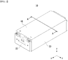
- Fig. 2 is a perspective view showing a state in which components constituting the battery module of Fig. 1 are combined.
- the conventional battery module 10 includes a battery cell stack 12 in which a plurality of battery cells 11 are stacked in one direction, a module frame 20 for housing the battery cell stack 12, end plates 15 for covering the front and rear surfaces of the battery cell stack and a busbar frame 13 formed between the end plate 15 and the front and rear surfaces of the battery cell stack 12.
- the module frame 20 includes a lower frame 30 that covers the lower part and both side surfaces of the battery cell stack 12 and an upper plate 40 that covers the upper surface of the battery cell stack 12.
- a heat conductive resin layer 31 is applied to a bottom surface for covering the lower part of the battery cell stack 12 in the lower frame 30. The heat conductive resin layer 31 can cool the heat generated in the battery cell stack 12 while transferring the heat generated in the battery cell stack 12 to the outside of the battery module 10.
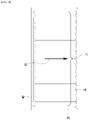
- Fig. 3 is a cross-sectional view taken along the cutting line A-A of Fig. 2 .
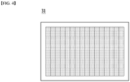
- Fig. 4 is a top view of the bottom surface of the module frame, which is a component of the battery module of Fig. 1 .
- the conventional battery module 10 has a structure for cooling the lower part of the battery cell stack 12, which is a structure in which the heat generated in the battery cells 11 flows in the first cooling direction D1 toward the lower part.
- the battery cell stack 12 has the feature that the temperature of the central battery cell is the highest and the temperature of the outer battery cell is the lowest.
- the battery cell stack 12 is configured such that the positive electrode and the negative electrode are positioned at both end parts based on the longitudinal direction, heat is generated relatively more than the central part in the charging/discharging process of the battery module 10.
- the battery cell 11 stops charging/discharging the entire battery module 10 when the voltage drops below a predetermined voltage value.
- the central battery cell of the battery cell stack 12 is as a reference.
- the outer battery cells are cooled more than the central battery cells, so that the voltage drop of the outer battery cell is severe, and can therefore be limited in terms of the use of the module.
- the heat conductive resin layer 31 is applied to the entire bottom surface of the lower frame 30 without considering the characteristics of the temperature deviation of the battery cell stack 12, and thus, a cooling deviation occurs in the battery cell stack 12.
- the heat conductive resin layer 31 has a large effect on the cooling of the battery cell stack 12, and the cooling deviation of the battery cell stack 12 due to the heat conductive resin layer 31 can be formed to be larger than that in a high temperature environment. Therefore, in the conventional battery module 10, the outer battery cells of the battery cell stack 12 are limited in terms of the use of the module due to a voltage drop, and there is a need to improve the cooling deviation between the central battery cell and the outer battery cell.
- a battery module comprising: a battery cell stack in which a plurality of battery cells are stacked; and a module frame for housing the battery cell stack, wherein a heat conductive resin layer is formed on the bottom surface of the module frame, wherein the heat conductive resin layer includes a first heat conductive resin layer and a second heat conductive resin layer, wherein the first heat conductive resin layer is formed adjacent to the front surface of the battery cell stack, and the second heat conductive resin layer is formed adjacent to the rear surface of the battery cell stack, and wherein at least a part of the first heat conductive resin layer and at least a part of the second heat conductive resin layer are spaced apart from each other.
- the first heat conductive resin layer and the second heat conductive resin layer may be formed to have equal width, and the first heat conductive resin layer and the second heat conductive resin layer may be spaced apart from each other.
- a first distance spaced apart between the first heat conductive resin layer and the second heat conductive resin layer may differ depending on a position on the bottom surface of the module frame.
- the first distance may increase from the center of the bottom surface of the module frame toward the outside.
- the first heat conductive resin layer and the second heat conductive resin layer formed at a position corresponding to the center of the bottom surface of the module frame may be in contact with each other.
- the first heat conductive resin layer and the second heat conductive resin layer formed at a position corresponding to the center of the bottom surface of the module frame may be spaced apart from each other.
- the first heat conductive resin layer and the second heat conductive resin layer may have shapes symmetrical with each other based on the longitudinal direction of the module frame.
- the first heat conductive resin layer and the second heat conductive resin layer may have shapes symmetrical with each other based on the width direction of the module frame.
- the first heat conductive resin layer and the second heat conductive resin layer may be composed of the same heat conductive resin material.
- the module frame may include a lower frame for housing the lower part and both side surfaces of the battery cell stack, and an upper plate for covering the upper surface of the battery cell stack.
- a battery pack comprising the above-mentioned battery module.
- a heat conductive resin layer whose length differs depending on the position of the bottom surface of the module frame corresponding to the battery cell stack is formed, thereby capable of improving the temperature deviation between the battery cells.
- planar when referred to as “planar”, it means when a target portion is viewed from the upper side, and when referred to as “cross-sectional”, it means when a target portion is viewed from the side of a cross section cut vertically.
- the battery module according to one embodiment of the present disclosure will be described.
- the description herein is made based on the front surface among the front and rear surfaces of the battery module, without being necessarily limited thereto, and even in the case of the rear surface, a description may be given with the same or similar contents.
- Fig. 5 is an exploded perspective view of a battery module according to one embodiment of the present disclosure.
- Fig. 6 is a diagram showing a heat conductive resin layer formed on the bottom surface of the module frame of Fig. 5 .
- the battery module 100 includes a battery cell stack 120 in which a plurality of battery cells 110 are stacked in a first direction (y-axis), a module frame 200 that houses the battery cell stack 120, end plates 150 that are positioned respectively on the front and rear surfaces of the battery cell stack 120, and a busbar frame 130 that is positioned between the battery cell stack 120 and the end plate 150.
- the module frame 200 includes a U-shaped frame 300 of which an upper surface, a front surface and a rear surface are opened, and an upper plate 400 that covers the upper part of the battery cell stack 120.
- a first heat conductive resin layer 310 may be positioned between the battery cell stack 120 and the bottom surface of the U-shaped frame 300.
- a heat conductive resin can be applied to the bottom surface of the U-shaped frame 300, before the battery cell stack 120 is mounted on the bottom surface of the U-shaped frame 300. Then, as the heat conductive resin is cured, the first heat conductive resin layer 310 can be formed. Thereby, the first heat conductive resin layer 310 can transfer the heat generated in the battery cell 110 to the bottom of the battery module 100 to cool the battery cell 110.
- the heat conductive resin layer 310 may include a first heat conductive resin layer 311 and a second heat conductive resin layer 315.
- the first heat conductive resin layer 311 and the second heat conductive resin layer 315 may be composed of the same heat conductive resin material.
- the first heat conductive resin layer 311 may be formed adjacent to the front surface of the battery cell stack 120, and the second heat conductive resin layer 315 may be formed adjacent to the rear surface of the battery cell stack 120.
- at least a part of the first heat conductive resin layer 311 and at least a part of the second heat conductive resin layer 315 may be spaced apart from each other.
- the first heat conductive resin layer 311 and the second heat conductive resin layer 315 may be spaced apart from each other. At this time, the first heat conductive resin layer 311 and the second heat conductive resin layer 315 may be formed to have mutually equal or different width. More preferably, the first heat conductive resin layer 311 and the second heat conductive resin layer 315 may be formed to have mutually equal width. That is, in the battery module 100 according to the present embodiment, the heat conductive resin layer 310 may be formed based on both end parts of the battery cell stack at the lower surface of the module frame 200.
- the heat conductive resin layer 310 can relatively reduce the degree of cooling for the outer battery cells of the battery cell stack, thereby reducing the cooling deviation within the battery cell stack.
- the heat conductive resin layer 310 can effectively cool the heat generated as the positive electrode and the negative electrode are positioned at both end parts based on the longitudinal direction of the battery cell stack.
- the heat conductive resin layer 310 is configured such that the first heat conductive resin layer 311 and the second heat conductive resin layer 315 are spaced apart from each other, which is economically advantageous in that the application amount of the heat conductive resin can be reduced and the manufacturing cost is reduced.
- the first heat conductive resin layer 311 and the second heat conductive resin layer 315 may have shapes symmetrical with each other based on the longitudinal direction of the module frame 200.
- the first heat conductive resin layer 311 and the second heat conductive resin layer 315 may have shapes symmetrical with each other based on the width direction of the module frame 200. Consequently, the heat conductive resin layer 310 can be cooled more uniformly with respect to the battery cell stack 120, so that the cooling deviation of the battery module 100 can be further improved.
- Figs. 7 and 8 are diagrams showing a heat conductive resin layer formed on a bottom surface of a module frame according to another embodiment of the present disclosure.
- a first distance spaced apart between the first heat conductive resin layer 311 and the second heat conductive resin layer 315 may differ depending on the position on the bottom surface of the battery module 200.
- Other contents are the same as those described above, and the heat conductive resin layer 310 will be mainly described below.
- a first distance between the first heat conductive resin layer 311 and the second heat conductive resin layer 315 may increase from the center of the bottom surface of the module frame 200 toward the outside.
- the width of the first heat conductive resin layer 311 and the second heat conductive resin layer 315 may decrease from the center of the bottom surface of the module frame 200 toward the outside.
- the first heat conductive resin layer 311 and the second heat conductive resin layer may be in contact with each other at a position corresponding to the center of the bottom surface of the module frame 200.
- the first heat conductive resin layer 311 and the second heat conductive resin layer may be spaced apart from each other at positions corresponding to the center of the bottom surface of the module frame 200.
- the heat conductive resin layer 310 is formed to have a relatively large width at a position corresponding to the central battery cell of the battery cell stack, and may be formed to have a relatively small width at a position corresponding to the outer battery cell of the battery cell stack. That is, in the battery module 100 according to the present embodiment, the heat conductive resin layer 310 is formed based on the center battery cell of the battery cell stack and both end parts of the battery cell stack at the lower surface of the module frame 200.
- the heat conductive resin layer 310 can further reduce the degree of cooling for the outer battery cells of the battery cell stack while maintaining the degree of cooling for the central battery cells of the battery cell stack, thereby further reducing the cooling deviation within the battery cell stack. Consequently, the heat conductive resin layer 310 reduces the degree of cooling for the outer battery cells of the battery cell stack while maintaining the degree of cooling for both end parts of the battery cell stack, thereby more efficiently reducing the cooling deviation within the battery cell stack.
- the voltage drop of the outer battery cell is relatively weaker, and even if the outer battery cell is used as a reference, it is not more limited in terms of the use of the module, and non-uniform degradation between the battery cells in the module resulting therefrom can be further prevented. In addition, the energy efficiency can be further increased.
- a distance at which the first heat conductive resin layer 311 and the second heat conductive resin layer 315 is spaced apart depending on the position of the module frame 200 is larger, which is economically advantageous in that the application amount of the thermal conductive resin can be further reduced, and the manufacturing cost is further reduced.
- the battery pack according to another embodiment of the present disclosure includes the battery module described above. Meanwhile, one or more of the battery modules according to the present embodiment may be packaged in a pack case to form a battery pack.
- the above-described battery module and battery pack including the same can be applied to various devices.
- a device may be applied to a vehicle means such as an electric bicycle, an electric vehicle, or a hybrid vehicle, but the present disclosure is not limited thereto, and is applicable to various devices capable of using a battery module, which also falls under the scope of the present disclosure.
- battery module 110 battery cell 120: battery cell stack 130: busbar frame 150: end plate 200: module frame 310: heat conductive resin layer
Landscapes
- Chemical & Material Sciences (AREA)
- Chemical Kinetics & Catalysis (AREA)
- Electrochemistry (AREA)
- General Chemical & Material Sciences (AREA)
- Engineering & Computer Science (AREA)
- Manufacturing & Machinery (AREA)
- Secondary Cells (AREA)
- Battery Mounting, Suspending (AREA)
Applications Claiming Priority (2)
| Application Number | Priority Date | Filing Date | Title |
|---|---|---|---|
| KR1020200121336A KR102890291B1 (ko) | 2020-09-21 | 2020-09-21 | 전지 모듈 및 이를 포함하는 전지팩 |
| PCT/KR2021/010478 WO2022059917A1 (ko) | 2020-09-21 | 2021-08-09 | 전지 모듈 및 이를 포함하는 전지팩 |
Publications (3)
| Publication Number | Publication Date |
|---|---|
| EP4120441A1 true EP4120441A1 (de) | 2023-01-18 |
| EP4120441A4 EP4120441A4 (de) | 2024-03-27 |
| EP4120441B1 EP4120441B1 (de) | 2025-02-12 |
Family
ID=80776212
Family Applications (1)
| Application Number | Title | Priority Date | Filing Date |
|---|---|---|---|
| EP21869540.1A Active EP4120441B1 (de) | 2020-09-21 | 2021-08-09 | Batteriemodul und batteriepack inbegriffen |
Country Status (8)
| Country | Link |
|---|---|
| US (1) | US12603349B2 (de) |
| EP (1) | EP4120441B1 (de) |
| JP (1) | JP7595962B2 (de) |
| KR (1) | KR102890291B1 (de) |
| CN (1) | CN115428233A (de) |
| ES (1) | ES3014540T3 (de) |
| HU (1) | HUE070303T2 (de) |
| WO (1) | WO2022059917A1 (de) |
Families Citing this family (1)
| Publication number | Priority date | Publication date | Assignee | Title |
|---|---|---|---|---|
| KR20250131625A (ko) * | 2024-02-27 | 2025-09-03 | 주식회사 엘지에너지솔루션 | 배터리 모듈, 이를 포함하는 배터리 팩 및 자동차 |
Family Cites Families (21)
| Publication number | Priority date | Publication date | Assignee | Title |
|---|---|---|---|---|
| JP4929702B2 (ja) * | 2005-12-19 | 2012-05-09 | 株式会社日立製作所 | 平面型表示装置 |
| KR101093959B1 (ko) | 2010-02-04 | 2011-12-15 | 에스비리모티브 주식회사 | 전지 모듈의 방열 장치 |
| JP6267571B2 (ja) * | 2014-04-23 | 2018-01-24 | 日立建機株式会社 | 作業機械及びこれに搭載される蓄電装置の冷却構造 |
| CN205099615U (zh) * | 2015-10-27 | 2016-03-23 | 广汉市众合塑料制品有限公司 | 新型胶粘带 |
| EP3419082B1 (de) | 2016-04-01 | 2021-06-16 | LG Chem, Ltd. | Batteriemodul |
| JP2017228364A (ja) | 2016-06-20 | 2017-12-28 | 株式会社豊田自動織機 | 電池パック |
| JP6717213B2 (ja) | 2017-01-18 | 2020-07-01 | 株式会社デンソー | 電池モジュール |
| CN107170782A (zh) | 2017-05-23 | 2017-09-15 | 京东方科技集团股份有限公司 | Oled基板及其制备方法、显示装置及其制备方法 |
| US10601003B2 (en) | 2017-10-30 | 2020-03-24 | Lg Chem, Ltd. | Battery module and method of assembling the battery module |
| KR102128588B1 (ko) * | 2017-12-26 | 2020-07-08 | 에스케이이노베이션 주식회사 | 배터리 모듈 및 이의 제조 방법 |
| KR102273195B1 (ko) * | 2017-12-27 | 2021-07-05 | 주식회사 엘지에너지솔루션 | 개선된 냉각 구조를 갖는 배터리 모듈 |
| CN207800719U (zh) | 2018-02-06 | 2018-08-31 | 宁德时代新能源科技股份有限公司 | 电池模组 |
| CN115411404A (zh) | 2018-03-07 | 2022-11-29 | Sk新能源株式会社 | 电池模块及其制造方法 |
| KR102751364B1 (ko) * | 2018-03-07 | 2025-01-07 | 에스케이온 주식회사 | 배터리 모듈 및 이의 제조 방법 |
| KR102113234B1 (ko) | 2018-04-20 | 2020-05-20 | 주식회사 엘지화학 | 수지 조성물 및 이를 포함하는 배터리 모듈 |
| KR102361272B1 (ko) | 2018-07-26 | 2022-02-09 | 주식회사 엘지에너지솔루션 | 냉각 효율이 향상된 배터리 모듈 및 이를 포함하는 배터리 팩 |
| CN208723044U (zh) * | 2018-08-24 | 2019-04-09 | 微宏动力系统(湖州)有限公司 | 一种电池模组 |
| JP7116653B2 (ja) * | 2018-09-20 | 2022-08-10 | 信越ポリマー株式会社 | 放熱構造体およびそれを備えるバッテリー |
| KR102456993B1 (ko) | 2019-02-13 | 2022-10-21 | 주식회사 엘지에너지솔루션 | 전지 모듈, 그 제조 방법 및 전지 모듈을 포함하는 전지팩 |
| KR102839344B1 (ko) * | 2019-06-07 | 2025-07-28 | 에스케이온 주식회사 | 배터리 모듈 |
| KR20210150843A (ko) * | 2020-06-04 | 2021-12-13 | 주식회사 엘지에너지솔루션 | 전지 모듈 및 이를 포함하는 전지팩 |
-
2020
- 2020-09-21 KR KR1020200121336A patent/KR102890291B1/ko active Active
-
2021
- 2021-08-09 CN CN202180028787.0A patent/CN115428233A/zh active Pending
- 2021-08-09 HU HUE21869540A patent/HUE070303T2/hu unknown
- 2021-08-09 ES ES21869540T patent/ES3014540T3/es active Active
- 2021-08-09 JP JP2022558533A patent/JP7595962B2/ja active Active
- 2021-08-09 EP EP21869540.1A patent/EP4120441B1/de active Active
- 2021-08-09 WO PCT/KR2021/010478 patent/WO2022059917A1/ko not_active Ceased
- 2021-08-09 US US17/913,098 patent/US12603349B2/en active Active
Also Published As
| Publication number | Publication date |
|---|---|
| CN115428233A (zh) | 2022-12-02 |
| JP2023519001A (ja) | 2023-05-09 |
| US12603349B2 (en) | 2026-04-14 |
| HUE070303T2 (hu) | 2025-05-28 |
| US20230135629A1 (en) | 2023-05-04 |
| JP7595962B2 (ja) | 2024-12-09 |
| EP4120441B1 (de) | 2025-02-12 |
| KR102890291B1 (ko) | 2025-11-21 |
| KR20220038920A (ko) | 2022-03-29 |
| WO2022059917A1 (ko) | 2022-03-24 |
| EP4120441A4 (de) | 2024-03-27 |
| ES3014540T3 (en) | 2025-04-23 |
Similar Documents
| Publication | Publication Date | Title |
|---|---|---|
| US20250239675A1 (en) | Battery Module and Battery Pack Including the Same | |
| US12155050B2 (en) | Battery module and battery pack including the same | |
| EP4318736A1 (de) | Batteriemodul und batteriepack damit | |
| US20230299431A1 (en) | Battery cell, battery module, and battery pack including the same | |
| US12451540B2 (en) | Battery module and battery pack including the same | |
| US12046731B2 (en) | Battery module, method for preparing the same and battery pack including the same | |
| US12224416B2 (en) | Battery module and battery pack including the same | |
| KR20230050093A (ko) | 전지 모듈 및 이를 포함하는 전지 팩 | |
| EP4120441B1 (de) | Batteriemodul und batteriepack inbegriffen | |
| CN114930616B (zh) | 电池模块及其制造方法 | |
| US12542311B2 (en) | Battery module and battery pack including the same | |
| US12482901B2 (en) | Battery module | |
| CN220121952U (zh) | 电池模块和包括该电池模块的电池组 | |
| US12327882B2 (en) | Battery module and battery pack including the same | |
| CN223884513U (zh) | 电池组和包括该电池组的装置 | |
| EP4243159A1 (de) | Batteriemodul und batteriepack damit | |
| KR20230036864A (ko) | 전지 모듈 및 이를 포함하는 전지 팩 |
Legal Events
| Date | Code | Title | Description |
|---|---|---|---|
| STAA | Information on the status of an ep patent application or granted ep patent |
Free format text: STATUS: THE INTERNATIONAL PUBLICATION HAS BEEN MADE |
|
| PUAI | Public reference made under article 153(3) epc to a published international application that has entered the european phase |
Free format text: ORIGINAL CODE: 0009012 |
|
| STAA | Information on the status of an ep patent application or granted ep patent |
Free format text: STATUS: REQUEST FOR EXAMINATION WAS MADE |
|
| 17P | Request for examination filed |
Effective date: 20221010 |
|
| AK | Designated contracting states |
Kind code of ref document: A1 Designated state(s): AL AT BE BG CH CY CZ DE DK EE ES FI FR GB GR HR HU IE IS IT LI LT LU LV MC MK MT NL NO PL PT RO RS SE SI SK SM TR |
|
| DAV | Request for validation of the european patent (deleted) | ||
| DAX | Request for extension of the european patent (deleted) | ||
| A4 | Supplementary search report drawn up and despatched |
Effective date: 20240227 |
|
| RIC1 | Information provided on ipc code assigned before grant |
Ipc: H01M 10/655 20140101ALN20240221BHEP Ipc: H01M 50/211 20210101ALI20240221BHEP Ipc: H01M 10/647 20140101ALI20240221BHEP Ipc: H01M 50/20 20210101ALI20240221BHEP Ipc: H01M 10/617 20140101ALI20240221BHEP Ipc: H01M 10/653 20140101AFI20240221BHEP |
|
| GRAP | Despatch of communication of intention to grant a patent |
Free format text: ORIGINAL CODE: EPIDOSNIGR1 |
|
| STAA | Information on the status of an ep patent application or granted ep patent |
Free format text: STATUS: GRANT OF PATENT IS INTENDED |
|
| RIC1 | Information provided on ipc code assigned before grant |
Ipc: H01M 10/655 20140101ALN20241018BHEP Ipc: H01M 50/211 20210101ALI20241018BHEP Ipc: H01M 10/647 20140101ALI20241018BHEP Ipc: H01M 50/20 20210101ALI20241018BHEP Ipc: H01M 10/617 20140101ALI20241018BHEP Ipc: H01M 10/653 20140101AFI20241018BHEP |
|
| GRAJ | Information related to disapproval of communication of intention to grant by the applicant or resumption of examination proceedings by the epo deleted |
Free format text: ORIGINAL CODE: EPIDOSDIGR1 |
|
| STAA | Information on the status of an ep patent application or granted ep patent |
Free format text: STATUS: REQUEST FOR EXAMINATION WAS MADE |
|
| RIC1 | Information provided on ipc code assigned before grant |
Ipc: H01M 10/655 20140101ALN20241031BHEP Ipc: H01M 50/211 20210101ALI20241031BHEP Ipc: H01M 10/647 20140101ALI20241031BHEP Ipc: H01M 50/20 20210101ALI20241031BHEP Ipc: H01M 10/617 20140101ALI20241031BHEP Ipc: H01M 10/653 20140101AFI20241031BHEP |
|
| GRAP | Despatch of communication of intention to grant a patent |
Free format text: ORIGINAL CODE: EPIDOSNIGR1 |
|
| STAA | Information on the status of an ep patent application or granted ep patent |
Free format text: STATUS: GRANT OF PATENT IS INTENDED |
|
| INTG | Intention to grant announced |
Effective date: 20241112 |
|
| INTC | Intention to grant announced (deleted) | ||
| GRAS | Grant fee paid |
Free format text: ORIGINAL CODE: EPIDOSNIGR3 |
|
| RIC1 | Information provided on ipc code assigned before grant |
Ipc: H01M 10/655 20140101ALN20241205BHEP Ipc: H01M 50/211 20210101ALI20241205BHEP Ipc: H01M 10/647 20140101ALI20241205BHEP Ipc: H01M 50/20 20210101ALI20241205BHEP Ipc: H01M 10/617 20140101ALI20241205BHEP Ipc: H01M 10/653 20140101AFI20241205BHEP |
|
| GRAA | (expected) grant |
Free format text: ORIGINAL CODE: 0009210 |
|
| STAA | Information on the status of an ep patent application or granted ep patent |
Free format text: STATUS: THE PATENT HAS BEEN GRANTED |
|
| INTG | Intention to grant announced |
Effective date: 20241211 |
|
| P01 | Opt-out of the competence of the unified patent court (upc) registered |
Free format text: CASE NUMBER: APP_65656/2024 Effective date: 20241212 |
|
| AK | Designated contracting states |
Kind code of ref document: B1 Designated state(s): AL AT BE BG CH CY CZ DE DK EE ES FI FR GB GR HR HU IE IS IT LI LT LU LV MC MK MT NL NO PL PT RO RS SE SI SK SM TR |
|
| REG | Reference to a national code |
Ref country code: GB Ref legal event code: FG4D |
|
| REG | Reference to a national code |
Ref country code: CH Ref legal event code: EP |
|
| REG | Reference to a national code |
Ref country code: DE Ref legal event code: R096 Ref document number: 602021026175 Country of ref document: DE |
|
| REG | Reference to a national code |
Ref country code: IE Ref legal event code: FG4D |
|
| REG | Reference to a national code |
Ref country code: ES Ref legal event code: FG2A Ref document number: 3014540 Country of ref document: ES Kind code of ref document: T3 Effective date: 20250423 |
|
| REG | Reference to a national code |
Ref country code: HU Ref legal event code: AG4A Ref document number: E070303 Country of ref document: HU |
|
| REG | Reference to a national code |
Ref country code: NL Ref legal event code: MP Effective date: 20250212 |
|
| PG25 | Lapsed in a contracting state [announced via postgrant information from national office to epo] |
Ref country code: RS Free format text: LAPSE BECAUSE OF FAILURE TO SUBMIT A TRANSLATION OF THE DESCRIPTION OR TO PAY THE FEE WITHIN THE PRESCRIBED TIME-LIMIT Effective date: 20250512 |
|
| PG25 | Lapsed in a contracting state [announced via postgrant information from national office to epo] |
Ref country code: FI Free format text: LAPSE BECAUSE OF FAILURE TO SUBMIT A TRANSLATION OF THE DESCRIPTION OR TO PAY THE FEE WITHIN THE PRESCRIBED TIME-LIMIT Effective date: 20250212 |
|
| PG25 | Lapsed in a contracting state [announced via postgrant information from national office to epo] |
Ref country code: PL Free format text: LAPSE BECAUSE OF FAILURE TO SUBMIT A TRANSLATION OF THE DESCRIPTION OR TO PAY THE FEE WITHIN THE PRESCRIBED TIME-LIMIT Effective date: 20250212 |
|
| REG | Reference to a national code |
Ref country code: LT Ref legal event code: MG9D |
|
| PG25 | Lapsed in a contracting state [announced via postgrant information from national office to epo] |
Ref country code: NO Free format text: LAPSE BECAUSE OF FAILURE TO SUBMIT A TRANSLATION OF THE DESCRIPTION OR TO PAY THE FEE WITHIN THE PRESCRIBED TIME-LIMIT Effective date: 20250512 Ref country code: IS Free format text: LAPSE BECAUSE OF FAILURE TO SUBMIT A TRANSLATION OF THE DESCRIPTION OR TO PAY THE FEE WITHIN THE PRESCRIBED TIME-LIMIT Effective date: 20250612 |
|
| PG25 | Lapsed in a contracting state [announced via postgrant information from national office to epo] |
Ref country code: NL Free format text: LAPSE BECAUSE OF FAILURE TO SUBMIT A TRANSLATION OF THE DESCRIPTION OR TO PAY THE FEE WITHIN THE PRESCRIBED TIME-LIMIT Effective date: 20250212 |
|
| PGFP | Annual fee paid to national office [announced via postgrant information from national office to epo] |
Ref country code: BE Payment date: 20250417 Year of fee payment: 5 |
|
| PG25 | Lapsed in a contracting state [announced via postgrant information from national office to epo] |
Ref country code: HR Free format text: LAPSE BECAUSE OF FAILURE TO SUBMIT A TRANSLATION OF THE DESCRIPTION OR TO PAY THE FEE WITHIN THE PRESCRIBED TIME-LIMIT Effective date: 20250212 |
|
| PG25 | Lapsed in a contracting state [announced via postgrant information from national office to epo] |
Ref country code: LV Free format text: LAPSE BECAUSE OF FAILURE TO SUBMIT A TRANSLATION OF THE DESCRIPTION OR TO PAY THE FEE WITHIN THE PRESCRIBED TIME-LIMIT Effective date: 20250212 Ref country code: PT Free format text: LAPSE BECAUSE OF FAILURE TO SUBMIT A TRANSLATION OF THE DESCRIPTION OR TO PAY THE FEE WITHIN THE PRESCRIBED TIME-LIMIT Effective date: 20250612 |
|
| PG25 | Lapsed in a contracting state [announced via postgrant information from national office to epo] |
Ref country code: GR Free format text: LAPSE BECAUSE OF FAILURE TO SUBMIT A TRANSLATION OF THE DESCRIPTION OR TO PAY THE FEE WITHIN THE PRESCRIBED TIME-LIMIT Effective date: 20250513 Ref country code: BG Free format text: LAPSE BECAUSE OF FAILURE TO SUBMIT A TRANSLATION OF THE DESCRIPTION OR TO PAY THE FEE WITHIN THE PRESCRIBED TIME-LIMIT Effective date: 20250212 |
|
| REG | Reference to a national code |
Ref country code: AT Ref legal event code: MK05 Ref document number: 1766991 Country of ref document: AT Kind code of ref document: T Effective date: 20250212 |
|
| PG25 | Lapsed in a contracting state [announced via postgrant information from national office to epo] |
Ref country code: SE Free format text: LAPSE BECAUSE OF FAILURE TO SUBMIT A TRANSLATION OF THE DESCRIPTION OR TO PAY THE FEE WITHIN THE PRESCRIBED TIME-LIMIT Effective date: 20250212 |
|
| PGFP | Annual fee paid to national office [announced via postgrant information from national office to epo] |
Ref country code: HU Payment date: 20250827 Year of fee payment: 5 |
|
| PG25 | Lapsed in a contracting state [announced via postgrant information from national office to epo] |
Ref country code: SM Free format text: LAPSE BECAUSE OF FAILURE TO SUBMIT A TRANSLATION OF THE DESCRIPTION OR TO PAY THE FEE WITHIN THE PRESCRIBED TIME-LIMIT Effective date: 20250212 |
|
| PGFP | Annual fee paid to national office [announced via postgrant information from national office to epo] |
Ref country code: ES Payment date: 20250911 Year of fee payment: 5 |
|
| PG25 | Lapsed in a contracting state [announced via postgrant information from national office to epo] |
Ref country code: DK Free format text: LAPSE BECAUSE OF FAILURE TO SUBMIT A TRANSLATION OF THE DESCRIPTION OR TO PAY THE FEE WITHIN THE PRESCRIBED TIME-LIMIT Effective date: 20250212 |
|
| PGFP | Annual fee paid to national office [announced via postgrant information from national office to epo] |
Ref country code: DE Payment date: 20250721 Year of fee payment: 5 |
|
| PG25 | Lapsed in a contracting state [announced via postgrant information from national office to epo] |
Ref country code: IT Free format text: LAPSE BECAUSE OF FAILURE TO SUBMIT A TRANSLATION OF THE DESCRIPTION OR TO PAY THE FEE WITHIN THE PRESCRIBED TIME-LIMIT Effective date: 20250212 |
|
| PGFP | Annual fee paid to national office [announced via postgrant information from national office to epo] |
Ref country code: GB Payment date: 20250722 Year of fee payment: 5 |
|
| PG25 | Lapsed in a contracting state [announced via postgrant information from national office to epo] |
Ref country code: AT Free format text: LAPSE BECAUSE OF FAILURE TO SUBMIT A TRANSLATION OF THE DESCRIPTION OR TO PAY THE FEE WITHIN THE PRESCRIBED TIME-LIMIT Effective date: 20250212 |
|
| PGFP | Annual fee paid to national office [announced via postgrant information from national office to epo] |
Ref country code: FR Payment date: 20250725 Year of fee payment: 5 |
|
| PG25 | Lapsed in a contracting state [announced via postgrant information from national office to epo] |
Ref country code: CZ Free format text: LAPSE BECAUSE OF FAILURE TO SUBMIT A TRANSLATION OF THE DESCRIPTION OR TO PAY THE FEE WITHIN THE PRESCRIBED TIME-LIMIT Effective date: 20250212 Ref country code: EE Free format text: LAPSE BECAUSE OF FAILURE TO SUBMIT A TRANSLATION OF THE DESCRIPTION OR TO PAY THE FEE WITHIN THE PRESCRIBED TIME-LIMIT Effective date: 20250212 |
|
| PG25 | Lapsed in a contracting state [announced via postgrant information from national office to epo] |
Ref country code: RO Free format text: LAPSE BECAUSE OF FAILURE TO SUBMIT A TRANSLATION OF THE DESCRIPTION OR TO PAY THE FEE WITHIN THE PRESCRIBED TIME-LIMIT Effective date: 20250212 |
|
| PG25 | Lapsed in a contracting state [announced via postgrant information from national office to epo] |
Ref country code: SK Free format text: LAPSE BECAUSE OF FAILURE TO SUBMIT A TRANSLATION OF THE DESCRIPTION OR TO PAY THE FEE WITHIN THE PRESCRIBED TIME-LIMIT Effective date: 20250212 |
|
| REG | Reference to a national code |
Ref country code: DE Ref legal event code: R097 Ref document number: 602021026175 Country of ref document: DE |
|
| PLBE | No opposition filed within time limit |
Free format text: ORIGINAL CODE: 0009261 |
|
| STAA | Information on the status of an ep patent application or granted ep patent |
Free format text: STATUS: NO OPPOSITION FILED WITHIN TIME LIMIT |
|
| REG | Reference to a national code |
Ref country code: CH Ref legal event code: L10 Free format text: ST27 STATUS EVENT CODE: U-0-0-L10-L00 (AS PROVIDED BY THE NATIONAL OFFICE) Effective date: 20251224 |
|
| 26N | No opposition filed |
Effective date: 20251113 |
|
| REG | Reference to a national code |
Ref country code: CH Ref legal event code: H13 Free format text: ST27 STATUS EVENT CODE: U-0-0-H10-H13 (AS PROVIDED BY THE NATIONAL OFFICE) Effective date: 20260324 |
|
| PG25 | Lapsed in a contracting state [announced via postgrant information from national office to epo] |
Ref country code: MC Free format text: LAPSE BECAUSE OF FAILURE TO SUBMIT A TRANSLATION OF THE DESCRIPTION OR TO PAY THE FEE WITHIN THE PRESCRIBED TIME-LIMIT Effective date: 20250212 |
|
| PG25 | Lapsed in a contracting state [announced via postgrant information from national office to epo] |
Ref country code: LU Free format text: LAPSE BECAUSE OF NON-PAYMENT OF DUE FEES Effective date: 20250809 |