EP4120706A1 - Verfahren zum konfigurieren eines kommunikationsmodus eines senders in einem funkkommunikationsnetz - Google Patents
Verfahren zum konfigurieren eines kommunikationsmodus eines senders in einem funkkommunikationsnetz Download PDFInfo
- Publication number
- EP4120706A1 EP4120706A1 EP22184323.8A EP22184323A EP4120706A1 EP 4120706 A1 EP4120706 A1 EP 4120706A1 EP 22184323 A EP22184323 A EP 22184323A EP 4120706 A1 EP4120706 A1 EP 4120706A1
- Authority
- EP
- European Patent Office
- Prior art keywords
- transmitter
- communication
- mode
- communication mode
- communication network
- Prior art date
- Legal status (The legal status is an assumption and is not a legal conclusion. Google has not performed a legal analysis and makes no representation as to the accuracy of the status listed.)
- Granted
Links
Images


Classifications
-
- H—ELECTRICITY
- H04—ELECTRIC COMMUNICATION TECHNIQUE
- H04W—WIRELESS COMMUNICATION NETWORKS
- H04W4/00—Services specially adapted for wireless communication networks; Facilities therefor
- H04W4/30—Services specially adapted for particular environments, situations or purposes
- H04W4/38—Services specially adapted for particular environments, situations or purposes for collecting sensor information
-
- H—ELECTRICITY
- H04—ELECTRIC COMMUNICATION TECHNIQUE
- H04L—TRANSMISSION OF DIGITAL INFORMATION, e.g. TELEGRAPHIC COMMUNICATION
- H04L69/00—Network arrangements, protocols or services independent of the application payload and not provided for in the other groups of this subclass
- H04L69/14—Multichannel or multilink protocols
-
- H—ELECTRICITY
- H04—ELECTRIC COMMUNICATION TECHNIQUE
- H04L—TRANSMISSION OF DIGITAL INFORMATION, e.g. TELEGRAPHIC COMMUNICATION
- H04L69/00—Network arrangements, protocols or services independent of the application payload and not provided for in the other groups of this subclass
- H04L69/18—Multiprotocol handlers, e.g. single devices capable of handling multiple protocols
-
- H—ELECTRICITY
- H04—ELECTRIC COMMUNICATION TECHNIQUE
- H04W—WIRELESS COMMUNICATION NETWORKS
- H04W4/00—Services specially adapted for wireless communication networks; Facilities therefor
- H04W4/50—Service provisioning or reconfiguring
-
- H—ELECTRICITY
- H04—ELECTRIC COMMUNICATION TECHNIQUE
- H04W—WIRELESS COMMUNICATION NETWORKS
- H04W4/00—Services specially adapted for wireless communication networks; Facilities therefor
- H04W4/70—Services for machine-to-machine communication [M2M] or machine type communication [MTC]
-
- H—ELECTRICITY
- H04—ELECTRIC COMMUNICATION TECHNIQUE
- H04W—WIRELESS COMMUNICATION NETWORKS
- H04W52/00—Power management, e.g. Transmission Power Control [TPC] or power classes
- H04W52/02—Power saving arrangements
- H04W52/0209—Power saving arrangements in terminal devices
- H04W52/0251—Power saving arrangements in terminal devices using monitoring of local events, e.g. events related to user activity
Definitions
- the present invention relates to a method of configuring a transmitter to communicate in a radio communication network.
- the present invention also relates to a transmitter implementing the configuration method.
- a home automation system usually includes several sensors, or transmitters, which communicate with a central unit through a radio protocol as part of a radio communication network.
- the central unit is battery-powered and it is then necessary to reduce the energy consumption of such a central unit as much as possible to allow it great autonomy, typically 10 years, while ensuring effective communication with the transmitters.
- the central activates a radio interface temporarily, for example over a period of 2 ms, and performs said activation at regular intervals, for example every 250 ms.
- each transmitter must transmit data frames consisting of a preamble comprising predetermined information followed by a data field.
- the preamble has a duration equal at least to the duration of the activation interval of the radio interface of the control unit.
- the central unit can keep its radio interface activated as soon as it detects a signal, corresponding to a preamble for example, which enables the central unit to receive each data frame transmitted by a transmitter.
- the plant is supplied by an electrical energy supply network of a building in which said plant is installed.
- the energy consumption of such a plant is then no longer a problem for its autonomy and it is then possible to activate the radio interface of the plant permanently. It is then advantageous to ensure greater autonomy for the transmitters, which are generally battery-powered, by applying a mode of communication in which the data frames do not include a preamble.
- a transmitter can automatically adapt to the mode of communication applied by a control unit in a radio communication network during the first association of the transmitter with said control unit.
- the transmitter can thus be adapted both to the communication mode of a battery-powered plant and to the communication mode of a plant powered by an electrical energy supply network.
- each data frame transmitted by the transmitter consists of a preamble of a predetermined duration followed by a data field when the transmitter applies the first mode of communication and each data frame transmitted by the sender consists only of a data field when the sender applies the second mode of communication.
- the first mode of communication allows a central unit, for example battery-powered, to reduce its energy consumption while ensuring the reception of messages sent by a transmitter.
- the second mode of communication makes it possible to optimize the reception of messages sent by a transmitter while minimizing the energy consumption of the transmitter.
- the method comprises: recording information representative of the selected communication mode, and applying the communication mode identified by said recorded representative information when the transmitter is powered up again after switching off.
- the configuration of the communication mode of the transmitter is carried out only during the first association of the transmitter to a control unit or during the first powering up of the transmitter in the radio communication network.
- the configuration of the communication mode of the transmitter does not need to be repeated as long as the transmitter remains in the same home automation system, in other words in the same radio communication network.
- the method includes deleting the recorded communication mode when a reset request is received.
- the invention also relates to a transmitter, in a radio communication network, the radio communication network comprising a control unit, the transmitter being able to selectively apply a first communication mode or a second communication mode.
- the transmitter comprises: means for broadcasting an association request in the communication network according to the first communication mode; means for selecting the first communication mode when an acknowledgment message is received from the central; means for selecting the second communication mode if no acknowledgment message is received when a predetermined time has elapsed since the broadcast of said association request; and means for applying the selected communication mode to communicate in the communication network.
- the invention also relates to a system comprising the transmitter according to any one of the embodiments and further comprising the central of the radio communication network.
- the central sends an acknowledgment message to the sender when the central receives a data frame from said sender and if the central applies the first mode of communication, and the central sends no message acknowledgment if the control unit applies the second communication mode.
- the invention also relates to a computer program, which can be stored on a medium and/or downloaded from a communication network, in order to be read by a processor of a transmitter.
- This computer program includes instructions for implementing the method mentioned above in any of their embodiments, when said program is executed by the transmitter's processor.
- the invention also relates to an information storage medium storing such a computer program.
- the Fig. 1 thus schematically illustrates a radio communication network 100 comprising a transmitter 110 and a central unit 120.
- the central unit 120 can be supplied with electrical energy, either by a building's electrical energy supply network, or by a battery.
- the central 120 is the manager of the radio communication network 100.
- the transmitter 110 can exchange messages with the central 120 in the radio communication network by selectively applying a first mode of communication or a second mode of communication.
- Transmitter 110 selects the first communication mode when central 120 applies the first communication mode. This is for example the case if the central unit 120 is supplied with electrical energy by a battery. Said first mode of communication is described below at Fig. 5 .
- the transmitter 110 selects the second communication mode when the central 120 applies the second communication mode. This is for example the case if the plant 120 is supplied with electrical energy by an electrical energy supply network. Said second mode of communication is described below at Fig. 6 .
- the central 120 can also be linked to other transmitters 130 by means of the network 100 of radio communication.
- the Fig. 2 illustrates an example of architecture of the plant 120 supplied with electrical energy by an electrical energy supply network.
- the plant 120 supplied with electrical energy by the electrical energy supply network comprises: a processor, microprocessor, or microcontroller 200; a volatile RAM (Random Access Memory) 203; a non-volatile memory ROM (Read Only Memory) 202; a storage unit or a storage medium reader, such as a hard disk HDD (“Hard Disk Drive” in English) 204; a radio interface 205; a supply 206 of electrical energy by the electrical energy supply network; and a communication bus 201 connecting the processor 200 to the ROM memory 202, to the RAM memory 203, to the hard disk HDD 204 and to the radio interface 205.
- a processor, microprocessor, or microcontroller 200 comprises: a volatile RAM (Random Access Memory) 203; a non-volatile memory ROM (Read Only Memory) 202; a storage unit or a storage medium reader, such as a hard disk HDD (“Hard Disk Drive” in English) 204; a radio interface 205; a supply 206 of electrical energy by
- Processor 200 is capable of executing instructions loaded into volatile RAM 203 from non-volatile ROM 202, external memory (not shown), storage media, or a network of communication.
- the processor 200 is capable of reading instructions from the volatile RAM 203 memory and executing them.
- These instructions form a computer program which causes the implementation, by the processor 200, of all or part of the method described here in relation to the central unit 120.
- All or part of the method described in relation to the plant can be implemented in software form by executing a set of instructions by a programmable machine, such as a DSP (Digital Signal Processor in English or Digital Signal Processing Unit in English). French) or a microcontroller or be implemented in hardware form by a dedicated machine or component, such as an FPGA (Field-Programmable Gate Array in English or Matrice de Portes Programmable sur le Terrain in French) or an ASIC (Application-Specific Integrated Circuit in English or Integrated Circuit Specific to an Application in French).
- a programmable machine such as a DSP (Digital Signal Processor in English or Digital Signal Processing Unit in English). French) or a microcontroller or be implemented in hardware form by a dedicated machine or component, such as an FPGA (Field-Programmable Gate Array in English or Matrice de Portes Programmable sur le Terrain in French) or an ASIC (Application-Specific Integrated Circuit in English or Integrated Circuit Specific to an Application in French).
- the Fig. 3 illustrates an example of the architecture of the plant supplied with electrical energy by a battery.
- the central unit 120 supplied with electrical energy by a battery comprises: a processor, microprocessor, or microcontroller 200; a volatile RAM (Random Access Memory) 203; a non-volatile memory ROM (Read Only Memory) 202; a storage unit or a storage medium reader, such as a hard disk HDD (“Hard Disk Drive” in English) 204; a radio interface 205; a supply 306 of electrical energy by a battery; and a communication bus 201 connecting the processor 200 to the ROM memory 202, to the RAM memory 203, to the hard disk HDD 204 and to the radio interface 205.
- a processor, microprocessor, or microcontroller 200 comprises: a volatile RAM (Random Access Memory) 203; a non-volatile memory ROM (Read Only Memory) 202; a storage unit or a storage medium reader, such as a hard disk HDD (“Hard Disk Drive
- Processor 200 is capable of executing instructions loaded into volatile RAM 203 from non-volatile ROM 202, external memory (not shown), storage media, or a network of communication.
- the processor 200 is capable of reading instructions from the volatile RAM 203 memory and executing them.
- These instructions form a computer program which causes the implementation, by the processor 200, of all or part of the method described in relation to the central unit 120.
- All or part of the method described here in relation to the central unit 120 can be implemented in software form by execution of a set of instructions by a programmable machine, such as a DSP (Digital Signal Processor in English or Signal Processing Unit). Digital in French) or a microcontroller or be implemented in hardware form by a dedicated machine or component, such as an FPGA (Field-Programmable Gate Array in English or Matrice de Portes Programmable sur le Terrain in French) or an ASIC (Application -Specific Integrated Circuit in English or Circuit Intégré Spécifique à une Application in French).
- a programmable machine such as a DSP (Digital Signal Processor in English or Signal Processing Unit). Digital in French) or a microcontroller or be implemented in hardware form by a dedicated machine or component, such as an FPGA (Field-Programmable Gate Array in English or Matrice de Portes Programmable sur le Terrain in French) or an ASIC (Application -Specific Integrated Circuit in English or Circuit Intégré Spéc
- the Fig. 4 illustrates an example architecture of transmitter 110 in which the present invention is implemented.
- the transmitter 110 a processor, microprocessor, or microcontroller 400; a volatile RAM (Random Access Memory) 403; a non-volatile memory ROM (Read Only Memory) 402; a storage unit or a storage medium reader, such as a hard disk HDD (Hard Disk Drive) 404; a radio interface 405 and a communication bus 401 connecting the processor 400 to the ROM memory 202, to the RAM memory 403, to the HDD hard disk 404 and to the radio interface 405.
- a processor, microprocessor, or microcontroller 400 a volatile RAM (Random Access Memory) 403; a non-volatile memory ROM (Read Only Memory) 402; a storage unit or a storage medium reader, such as a hard disk HDD (Hard Disk Drive) 404; a radio interface 405 and a communication bus 401 connecting the processor 400 to the ROM memory 202, to the RAM memory 403, to the HDD hard disk 404 and to the radio interface 405.
- Processor 400 is capable of executing instructions loaded into volatile RAM 403 from non-volatile ROM 402, external memory (not shown), storage media, or a network of communication. When transmitter 110 is powered up, processor 400 is able to read instructions from volatile RAM 203 and execute them. These instructions form a computer program which causes the implementation, by the processor 400, of all or part of the method described in relation to the transmitter 110.
- All or part of the process described here in relation to the transmitter 110 can be implemented in software form by execution of a set of instructions by a programmable machine, such as a DSP (Digital Signal Processor in English or Processing Unit of Signal Numérique in French) or a microcontroller or be implemented in hardware form by a dedicated machine or component, such as an FPGA (Field-Programmable Gate Array in English or Matrice de Portes Programmable sur le Terrain in French) or an ASIC ( Application-Specific Integrated Circuit in English or Circuit Intégré Spécifique à un Application in French).
- a programmable machine such as a DSP (Digital Signal Processor in English or Processing Unit of Signal Numérique in French) or a microcontroller or be implemented in hardware form by a dedicated machine or component, such as an FPGA (Field-Programmable Gate Array in English or Matrice de Portes Programmable sur le Terrain in French) or an ASIC ( Application-Specific Integrated Circuit in English or Circuit Intégré Spécifique
- the transmitter 110 further comprises a power supply 306 of electrical energy by a battery.
- the Fig. 5 illustrates a timing diagram of signals exchanged in the radio communication network 100 when the transmitter 110 and the central 120 apply the first mode of communication.
- each data frame 51 transmitted by the transmitter 110 consists of a preamble PRE of a first predetermined duration and comprising predetermined information followed by a data field C.
- the predetermined information of the preamble PRE comprises a predefined pattern repeated throughout the first predetermined duration.
- the predefined pattern for example consists of a word of 16 predefined bits, such as B4B4 or even 9A9A in hexadecimal notation.
- the preamble PRE thus allows a receiver which detects the predefined pattern, to keep its radio interface activated to receive the data field C.
- the data field C comprises an identifier of the transmitter 110.
- the data field C may include information representative of a change of state of a variable such as for example information representative of the opening or closing of a door.
- the central unit 120 When the central unit 120 applies the first mode of communication, the central unit 120 activates its radio interface 205 at regularly spaced intervals of a duration ⁇ t at most equal to the first predetermined duration, and for a second predetermined duration dt much less than the duration ⁇ t .
- the control unit 120 thus activates its radio interface at times t1, t2 and t4. If the radio interface 205 detects the reception of no signal during said second predetermined duration dt, the control unit 120 deactivates its radio interface 205. This is for example the case at time t1 or at time t4.
- the central 120 if the radio interface 205 detects the reception of a signal, for example a preamble PRE of a data frame 51 emitted by the transmitter 110, the central 120 maintains its radio interface 205 activated so as to fully receive the data field C of the data frame 51. This is the case for example at time t2.
- the central 120 sends an acknowledgment message AC to the transmitter 110 that sent the data frame 51 then deactivates its radio interface 205 for the duration ⁇ t if no other signal is present. received.
- the AC acknowledgment message includes an identifier of said transmitter 110 having transmitted the data frame 51 as well as an identifier of the central unit 120 which transmits said AC acknowledgment.
- the acknowledgment message AC further comprises information representative of the type of frame received, such as for example information representative of an association frame if said data frame 51 received is an association frame or according to another example information representative of an event detection frame if the data frame 51 received is an event detection frame.
- the transmitter 110 maintains its radio interface 405 activated after having transmitted the data frame 51 as long as an acknowledgment AC is not received.
- the transmitter 110 receives the acknowledgment message AC transmitted by the central 120, the transmitter 110 then considers that the transmitted data frame 51 has been correctly received.
- the transmitter 110 if the transmitter 110 does not receive an acknowledgment message AC in response to the transmission of a data frame 51, for example after a second predetermined delay, the transmitter 110 retransmits said data frame 51.
- the data frame 51 can be retransmitted on the same transmission radio channel or on a different transmission radio channel.
- the Fig. 6 illustrates a timing diagram of signals exchanged in the radio communication network 100 when the transmitter 110 and the central 120 apply the second mode of communication.
- the central 120 When the central 120 applies the second mode of communication, the central 120 activates its radio interface 205 permanently and can therefore potentially receive at any time a data frame 52 transmitted by the transmitter 110.
- each data frame 52 transmitted by the transmitter consists solely of a data field C and therefore does not include a preamble.
- the central 120 does not send an acknowledgment in response to the reception of a data frame 52.
- each data frame 52 is transmitted successively several times, at regular intervals and a predetermined number of times.
- the show of a data frame 52 several times by the transmitter 110 thus makes it possible to maximize the probabilities of reception of said data frame 52 by the central 120.
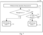
- Fig. 7 illustrates an algorithm, implemented by the transmitter, representing a method of configuring 700 the communication mode of the transmitter 110.
- the communication mode of the transmitter 110 is not predefined.
- the transmitter 110 broadcasts an association request in the radio communication network 100.
- Said association request can be sent either automatically or following the execution of a manual command, such as pressing a dedicated button, by a user of the transmitter 110. This is for example the case during a first installation of the transmitter 110 in the network 100 of radio communication.
- the association request includes an identifier of the transmitter 110. If the association request is received by a central 120 of the radio communication network 100 configured to add a transmitter, the central 120 then records an identifier of the transmitter 110 in order to be able to communicate with the transmitter 110. The association request thus enables the transmitter to communicate its identifier to the central 120 in order to be recognized in the radio communication network 100 and to be able to communicate.
- the association request can comprise one or more data frames.
- the association request is broadcast several times, for example three times. Each association request data frame is then transmitted each time the association request is broadcast.
- each data frame 51 of the association request consists of a preamble PRE followed by a data field C.
- a next step 702 the transmitter determines whether an acknowledgment message AC is received from a central 120 in response to the association request and for each data frame 51 of the association request broadcast. This is the case if said central 120 applies the first mode of communication. If so, a step 703 is performed. Otherwise, a step 704 is performed.
- transmitter 110 selects the first communication mode.
- the issuer defines that the first mode of communication is to be applied to carry out any exchange of data with the central 120 in the network 100 of radio communications.
- the transmitter 110 automatically detects that the central 120 applies the first mode of communication and then selects said first mode of communication.
- step 704 the transmitter 110 determines if a first predetermined time has elapsed since the broadcast of the association request in step 701. If so, a step 708 is carried out. Otherwise, step 702 is repeated.
- the first predetermined period is for example 24 hours.
- the transmitter 110 has not received an acknowledgment in response to the broadcast association request and the first delay has elapsed, the transmitter 110 then selects the second communication mode.
- the transmitter defines that the second mode of communication is to be applied for the exchange of data with the central unit 120 in the network 100 of radio communication.
- the transmitter 110 automatically selects the communication mode applied by the central 120 with which the transmitter 110 is associated.
- the transmitter 110 broadcasts an additional association request, either automatically with, for example, a periodicity of 1h30, or following the execution of a manual command, such as pressing a dedicated button, by a user of the transmitter 110.
- the first predetermined delay is defined from the broadcast of the first association request.
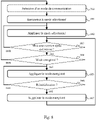
- the Fig. 8 illustrates an algorithm for time management of the transmitter's communication mode.
- the transmitter 110 performs the configuration process 700 of the communication mode described in Fig. 7 and thereby selects either the first communication mode or the second communication mode.
- the transmitter 110 records information representative of the mode of communication selected previously in step 700.
- the transmitter 110 applies the communication mode selected to carry out exchanges in the radio communication network 100 with the central 120.
- step 803 the transmitter 110 determines whether the transmitter 110 is powered up after said transmitter 110 has been turned off. If this is the case, a step 804 is performed. Otherwise, step 802 is repeated.
- step 804 the transmitter 110 determines whether information representative of a mode of communication is recorded. If this is the case, the sender 110 performs step 805. Otherwise, the sender 110 must select a communication mode and repeats step 700 for this.
- the transmitter 110 applies the communication mode identified by the information representative of said recorded communication mode in order to communicate with the central 120 in the radio communication network 100.
- the transmitter 110 does not need to perform the communication mode configuration process 700 each time the power is switched off and switched on and can communicate directly with the central unit 120 when a communication mode is identified by recorded information.
- a reset request can be made by a user by pressing a button on the transmitter for a period of 30s for example. Such a reset request can be made to use a transmitter in a new context such as a new radio communication network 100. If a reset request is received, step 807 is performed. Otherwise, step 805 is repeated.
- the transmitter 110 deletes the information representative of the mode of communication recorded at step 802.
- the transmitter 110 then repeats step 803.
Landscapes
- Engineering & Computer Science (AREA)
- Computer Networks & Wireless Communication (AREA)
- Signal Processing (AREA)
- Computer Security & Cryptography (AREA)
- Mobile Radio Communication Systems (AREA)
- Communication Control (AREA)
Applications Claiming Priority (1)
| Application Number | Priority Date | Filing Date | Title |
|---|---|---|---|
| FR2107666A FR3125379B1 (fr) | 2021-07-15 | 2021-07-15 | Procede de configuration d’un mode de communication d’un emetteur dans un reseau de communication radio |
Publications (2)
| Publication Number | Publication Date |
|---|---|
| EP4120706A1 true EP4120706A1 (de) | 2023-01-18 |
| EP4120706B1 EP4120706B1 (de) | 2024-11-20 |
Family
ID=77711086
Family Applications (1)
| Application Number | Title | Priority Date | Filing Date |
|---|---|---|---|
| EP22184323.8A Active EP4120706B1 (de) | 2021-07-15 | 2022-07-12 | Verfahren zum konfigurieren eines kommunikationsmodus eines senders in einem funkkommunikationsnetz |
Country Status (2)
| Country | Link |
|---|---|
| EP (1) | EP4120706B1 (de) |
| FR (1) | FR3125379B1 (de) |
Citations (1)
| Publication number | Priority date | Publication date | Assignee | Title |
|---|---|---|---|---|
| US20080279560A1 (en) * | 2005-01-28 | 2008-11-13 | Shohei Osawa | Communication Device, Communication System, Communication Method, Communication Program, and Communication Circuit |
-
2021
- 2021-07-15 FR FR2107666A patent/FR3125379B1/fr active Active
-
2022
- 2022-07-12 EP EP22184323.8A patent/EP4120706B1/de active Active
Patent Citations (1)
| Publication number | Priority date | Publication date | Assignee | Title |
|---|---|---|---|---|
| US20080279560A1 (en) * | 2005-01-28 | 2008-11-13 | Shohei Osawa | Communication Device, Communication System, Communication Method, Communication Program, and Communication Circuit |
Also Published As
| Publication number | Publication date |
|---|---|
| FR3125379B1 (fr) | 2024-09-13 |
| FR3125379A1 (fr) | 2023-01-20 |
| EP4120706B1 (de) | 2024-11-20 |
Similar Documents
| Publication | Publication Date | Title |
|---|---|---|
| EP0703717A1 (de) | Batteriesparanordnung eines Systemes mit einem an ein Peripheriegerätangeschlossenen Funktelefon | |
| EP2894872B1 (de) | Verfahren zur Verlaufsplanung der Aufgaben in einem PLC-Netz | |
| WO2013144516A1 (fr) | Procede de traitement de la reception d'un signal de communication par voie radio, procede de traitement de l'emission, dispositifs et programmes d'ordinateur associes | |
| EP3533183B1 (de) | Verfahren zur auswahl eines gateway zur übertragung eines rahmens | |
| EP3182281A1 (de) | Übertragungsverfahren einer neuen software-version an mindestens einen stromzähler über ein kommunikationsnetz | |
| EP4120706B1 (de) | Verfahren zum konfigurieren eines kommunikationsmodus eines senders in einem funkkommunikationsnetz | |
| EP3053309B1 (de) | Verbesserte verwaltung von netzwerkverbindungen | |
| WO2010007274A1 (fr) | Procede de transmission d'un signal de communication | |
| EP2514246B1 (de) | Verbessertes Verfahren zur Übertragund eines Kommunikationssignals | |
| EP2099005A1 (de) | Kommunikationsverfahren zwischen einem ersten und einem zweiten Knoten einer Heimanlage | |
| EP3016290B1 (de) | Steuerungsverfahren der aktivierung einer empfangskette eines funkmoduls | |
| WO2013107975A1 (fr) | Reveil a distance d'un equipement connecte a un reseau a liens multiples | |
| EP3712359B1 (de) | Vernetzte betätigungsvorrichtung für schliesssystem eines fensters oder einer tür | |
| EP1499154B1 (de) | Verfahren zur bidirektionalen Funkkommunikation zwischen mehreren Modulen eines Systemes | |
| EP4482225B1 (de) | Verfahren zur verwaltung eines aktivierungszustands einer knotenvorrichtung eines kommunikationsnetzwerks, entsprechende vorrichtung, knotenvorrichtung, system und computerprogramm | |
| EP3692748B1 (de) | Verfahren zur verwaltung der von einem funkmodul verbrauchten energie | |
| EP3836640A1 (de) | Verfahren und system für die übertragung von datenrahmen in einem funkkommunikationsnetz eines gebäudes | |
| WO2025119690A1 (fr) | Procédé de gestion de l'acheminement de messages dans un réseau maillé | |
| EP3545384B1 (de) | System zur verwaltung des stromverbrauchs in einer vorrichtung | |
| EP3122006B1 (de) | Verfahren zur auswahl einer elternknoten-vorrichtung in einem baumförmigen kommunikationsnetz | |
| EP3211841B1 (de) | Verfahren zum entscheiden über die weiterleitung einer kopie einer wegermittlungsanfrage durch übertragung in einem kommunikationsnetz | |
| EP2517412B1 (de) | Sicherungsvorrichtung einer upnp-steuerung | |
| EP4668715A1 (de) | Verfahren zur konfiguration eines kommunikationsprotokolls einer knotenvorrichtung | |
| EP4142240A1 (de) | Verfahren zur verwaltung einer controller-funktion durch ein gerät eines router-netzwerks | |
| EP2267933B1 (de) | Empfangsbestätigungsverfahren eines ferngesteuerten Systems von Hausgeräten |
Legal Events
| Date | Code | Title | Description |
|---|---|---|---|
| PUAI | Public reference made under article 153(3) epc to a published international application that has entered the european phase |
Free format text: ORIGINAL CODE: 0009012 |
|
| STAA | Information on the status of an ep patent application or granted ep patent |
Free format text: STATUS: THE APPLICATION HAS BEEN PUBLISHED |
|
| AK | Designated contracting states |
Kind code of ref document: A1 Designated state(s): AL AT BE BG CH CY CZ DE DK EE ES FI FR GB GR HR HU IE IS IT LI LT LU LV MC MK MT NL NO PL PT RO RS SE SI SK SM TR |
|
| STAA | Information on the status of an ep patent application or granted ep patent |
Free format text: STATUS: REQUEST FOR EXAMINATION WAS MADE |
|
| 17P | Request for examination filed |
Effective date: 20230328 |
|
| RBV | Designated contracting states (corrected) |
Designated state(s): AL AT BE BG CH CY CZ DE DK EE ES FI FR GB GR HR HU IE IS IT LI LT LU LV MC MK MT NL NO PL PT RO RS SE SI SK SM TR |
|
| STAA | Information on the status of an ep patent application or granted ep patent |
Free format text: STATUS: EXAMINATION IS IN PROGRESS |
|
| 17Q | First examination report despatched |
Effective date: 20230907 |
|
| GRAP | Despatch of communication of intention to grant a patent |
Free format text: ORIGINAL CODE: EPIDOSNIGR1 |
|
| GRAP | Despatch of communication of intention to grant a patent |
Free format text: ORIGINAL CODE: EPIDOSNIGR1 |
|
| STAA | Information on the status of an ep patent application or granted ep patent |
Free format text: STATUS: GRANT OF PATENT IS INTENDED |
|
| INTG | Intention to grant announced |
Effective date: 20240614 |
|
| GRAS | Grant fee paid |
Free format text: ORIGINAL CODE: EPIDOSNIGR3 |
|
| GRAA | (expected) grant |
Free format text: ORIGINAL CODE: 0009210 |
|
| STAA | Information on the status of an ep patent application or granted ep patent |
Free format text: STATUS: THE PATENT HAS BEEN GRANTED |
|
| AK | Designated contracting states |
Kind code of ref document: B1 Designated state(s): AL AT BE BG CH CY CZ DE DK EE ES FI FR GB GR HR HU IE IS IT LI LT LU LV MC MK MT NL NO PL PT RO RS SE SI SK SM TR |
|
| REG | Reference to a national code |
Ref country code: GB Ref legal event code: FG4D Free format text: NOT ENGLISH |
|
| REG | Reference to a national code |
Ref country code: CH Ref legal event code: EP |
|
| REG | Reference to a national code |
Ref country code: DE Ref legal event code: R096 Ref document number: 602022007832 Country of ref document: DE |
|
| REG | Reference to a national code |
Ref country code: IE Ref legal event code: FG4D Free format text: LANGUAGE OF EP DOCUMENT: FRENCH |
|
| REG | Reference to a national code |
Ref country code: LT Ref legal event code: MG9D |
|
| REG | Reference to a national code |
Ref country code: NL Ref legal event code: MP Effective date: 20241120 |
|
| PG25 | Lapsed in a contracting state [announced via postgrant information from national office to epo] |
Ref country code: IS Free format text: LAPSE BECAUSE OF FAILURE TO SUBMIT A TRANSLATION OF THE DESCRIPTION OR TO PAY THE FEE WITHIN THE PRESCRIBED TIME-LIMIT Effective date: 20250320 Ref country code: HR Free format text: LAPSE BECAUSE OF FAILURE TO SUBMIT A TRANSLATION OF THE DESCRIPTION OR TO PAY THE FEE WITHIN THE PRESCRIBED TIME-LIMIT Effective date: 20241120 Ref country code: PT Free format text: LAPSE BECAUSE OF FAILURE TO SUBMIT A TRANSLATION OF THE DESCRIPTION OR TO PAY THE FEE WITHIN THE PRESCRIBED TIME-LIMIT Effective date: 20250320 |
|
| PG25 | Lapsed in a contracting state [announced via postgrant information from national office to epo] |
Ref country code: FI Free format text: LAPSE BECAUSE OF FAILURE TO SUBMIT A TRANSLATION OF THE DESCRIPTION OR TO PAY THE FEE WITHIN THE PRESCRIBED TIME-LIMIT Effective date: 20241120 Ref country code: NL Free format text: LAPSE BECAUSE OF FAILURE TO SUBMIT A TRANSLATION OF THE DESCRIPTION OR TO PAY THE FEE WITHIN THE PRESCRIBED TIME-LIMIT Effective date: 20241120 |
|
| REG | Reference to a national code |
Ref country code: AT Ref legal event code: MK05 Ref document number: 1744654 Country of ref document: AT Kind code of ref document: T Effective date: 20241120 |
|
| PG25 | Lapsed in a contracting state [announced via postgrant information from national office to epo] |
Ref country code: BG Free format text: LAPSE BECAUSE OF FAILURE TO SUBMIT A TRANSLATION OF THE DESCRIPTION OR TO PAY THE FEE WITHIN THE PRESCRIBED TIME-LIMIT Effective date: 20241120 |
|
| PG25 | Lapsed in a contracting state [announced via postgrant information from national office to epo] |
Ref country code: ES Free format text: LAPSE BECAUSE OF FAILURE TO SUBMIT A TRANSLATION OF THE DESCRIPTION OR TO PAY THE FEE WITHIN THE PRESCRIBED TIME-LIMIT Effective date: 20241120 |
|
| PG25 | Lapsed in a contracting state [announced via postgrant information from national office to epo] |
Ref country code: NO Free format text: LAPSE BECAUSE OF FAILURE TO SUBMIT A TRANSLATION OF THE DESCRIPTION OR TO PAY THE FEE WITHIN THE PRESCRIBED TIME-LIMIT Effective date: 20250220 |
|
| PG25 | Lapsed in a contracting state [announced via postgrant information from national office to epo] |
Ref country code: GR Free format text: LAPSE BECAUSE OF FAILURE TO SUBMIT A TRANSLATION OF THE DESCRIPTION OR TO PAY THE FEE WITHIN THE PRESCRIBED TIME-LIMIT Effective date: 20250221 Ref country code: AT Free format text: LAPSE BECAUSE OF FAILURE TO SUBMIT A TRANSLATION OF THE DESCRIPTION OR TO PAY THE FEE WITHIN THE PRESCRIBED TIME-LIMIT Effective date: 20241120 Ref country code: LV Free format text: LAPSE BECAUSE OF FAILURE TO SUBMIT A TRANSLATION OF THE DESCRIPTION OR TO PAY THE FEE WITHIN THE PRESCRIBED TIME-LIMIT Effective date: 20241120 |
|
| PG25 | Lapsed in a contracting state [announced via postgrant information from national office to epo] |
Ref country code: PL Free format text: LAPSE BECAUSE OF FAILURE TO SUBMIT A TRANSLATION OF THE DESCRIPTION OR TO PAY THE FEE WITHIN THE PRESCRIBED TIME-LIMIT Effective date: 20241120 |
|
| PG25 | Lapsed in a contracting state [announced via postgrant information from national office to epo] |
Ref country code: RS Free format text: LAPSE BECAUSE OF FAILURE TO SUBMIT A TRANSLATION OF THE DESCRIPTION OR TO PAY THE FEE WITHIN THE PRESCRIBED TIME-LIMIT Effective date: 20250220 |
|
| PG25 | Lapsed in a contracting state [announced via postgrant information from national office to epo] |
Ref country code: SM Free format text: LAPSE BECAUSE OF FAILURE TO SUBMIT A TRANSLATION OF THE DESCRIPTION OR TO PAY THE FEE WITHIN THE PRESCRIBED TIME-LIMIT Effective date: 20241120 |
|
| PG25 | Lapsed in a contracting state [announced via postgrant information from national office to epo] |
Ref country code: DK Free format text: LAPSE BECAUSE OF FAILURE TO SUBMIT A TRANSLATION OF THE DESCRIPTION OR TO PAY THE FEE WITHIN THE PRESCRIBED TIME-LIMIT Effective date: 20241120 |
|
| PG25 | Lapsed in a contracting state [announced via postgrant information from national office to epo] |
Ref country code: EE Free format text: LAPSE BECAUSE OF FAILURE TO SUBMIT A TRANSLATION OF THE DESCRIPTION OR TO PAY THE FEE WITHIN THE PRESCRIBED TIME-LIMIT Effective date: 20241120 |
|
| PG25 | Lapsed in a contracting state [announced via postgrant information from national office to epo] |
Ref country code: RO Free format text: LAPSE BECAUSE OF FAILURE TO SUBMIT A TRANSLATION OF THE DESCRIPTION OR TO PAY THE FEE WITHIN THE PRESCRIBED TIME-LIMIT Effective date: 20241120 |
|
| PG25 | Lapsed in a contracting state [announced via postgrant information from national office to epo] |
Ref country code: SK Free format text: LAPSE BECAUSE OF FAILURE TO SUBMIT A TRANSLATION OF THE DESCRIPTION OR TO PAY THE FEE WITHIN THE PRESCRIBED TIME-LIMIT Effective date: 20241120 |
|
| PG25 | Lapsed in a contracting state [announced via postgrant information from national office to epo] |
Ref country code: CZ Free format text: LAPSE BECAUSE OF FAILURE TO SUBMIT A TRANSLATION OF THE DESCRIPTION OR TO PAY THE FEE WITHIN THE PRESCRIBED TIME-LIMIT Effective date: 20241120 |
|
| PG25 | Lapsed in a contracting state [announced via postgrant information from national office to epo] |
Ref country code: IT Free format text: LAPSE BECAUSE OF FAILURE TO SUBMIT A TRANSLATION OF THE DESCRIPTION OR TO PAY THE FEE WITHIN THE PRESCRIBED TIME-LIMIT Effective date: 20241120 |
|
| REG | Reference to a national code |
Ref country code: DE Ref legal event code: R097 Ref document number: 602022007832 Country of ref document: DE |
|
| PG25 | Lapsed in a contracting state [announced via postgrant information from national office to epo] |
Ref country code: SE Free format text: LAPSE BECAUSE OF FAILURE TO SUBMIT A TRANSLATION OF THE DESCRIPTION OR TO PAY THE FEE WITHIN THE PRESCRIBED TIME-LIMIT Effective date: 20241120 |
|
| PLBE | No opposition filed within time limit |
Free format text: ORIGINAL CODE: 0009261 |
|
| STAA | Information on the status of an ep patent application or granted ep patent |
Free format text: STATUS: NO OPPOSITION FILED WITHIN TIME LIMIT |
|
| PGFP | Annual fee paid to national office [announced via postgrant information from national office to epo] |
Ref country code: FR Payment date: 20250725 Year of fee payment: 4 |
|
| 26N | No opposition filed |
Effective date: 20250821 |
|
| REG | Reference to a national code |
Ref country code: DE Ref legal event code: R119 Ref document number: 602022007832 Country of ref document: DE |
|
| REG | Reference to a national code |
Ref country code: CH Ref legal event code: H13 Free format text: ST27 STATUS EVENT CODE: U-0-0-H10-H13 (AS PROVIDED BY THE NATIONAL OFFICE) Effective date: 20260224 |
|
| PG25 | Lapsed in a contracting state [announced via postgrant information from national office to epo] |
Ref country code: LU Free format text: LAPSE BECAUSE OF NON-PAYMENT OF DUE FEES Effective date: 20250712 |
|
| REG | Reference to a national code |
Ref country code: BE Ref legal event code: MM Effective date: 20250731 |
|
| PG25 | Lapsed in a contracting state [announced via postgrant information from national office to epo] |
Ref country code: DE Free format text: LAPSE BECAUSE OF NON-PAYMENT OF DUE FEES Effective date: 20260203 |
|
| PG25 | Lapsed in a contracting state [announced via postgrant information from national office to epo] |
Ref country code: BE Free format text: LAPSE BECAUSE OF NON-PAYMENT OF DUE FEES Effective date: 20250731 |
|
| PG25 | Lapsed in a contracting state [announced via postgrant information from national office to epo] |
Ref country code: CH Free format text: LAPSE BECAUSE OF NON-PAYMENT OF DUE FEES Effective date: 20250731 |