EP4121995B1 - Appareil électroménager comportant un dispositif de surveillance de porte - Google Patents
Appareil électroménager comportant un dispositif de surveillance de porte Download PDFInfo
- Publication number
- EP4121995B1 EP4121995B1 EP21710225.0A EP21710225A EP4121995B1 EP 4121995 B1 EP4121995 B1 EP 4121995B1 EP 21710225 A EP21710225 A EP 21710225A EP 4121995 B1 EP4121995 B1 EP 4121995B1
- Authority
- EP
- European Patent Office
- Prior art keywords
- contact
- door
- household appliance
- contact part
- parts
- Prior art date
- Legal status (The legal status is an assumption and is not a legal conclusion. Google has not performed a legal analysis and makes no representation as to the accuracy of the status listed.)
- Active
Links
Images

Classifications
-
- H—ELECTRICITY
- H01—ELECTRIC ELEMENTS
- H01H—ELECTRIC SWITCHES; RELAYS; SELECTORS; EMERGENCY PROTECTIVE DEVICES
- H01H13/00—Switches having rectilinearly-movable operating part or parts adapted for pushing or pulling in one direction only, e.g. push-button switch
- H01H13/02—Details
- H01H13/12—Movable parts; Contacts mounted thereon
- H01H13/14—Operating parts, e.g. push-button
- H01H13/18—Operating parts, e.g. push-button adapted for actuation at a limit or other predetermined position in the path of a body, the relative movement of switch and body being primarily for a purpose other than the actuation of the switch, e.g. door switch, limit switch, floor-levelling switch of a lift
- H01H13/183—Operating parts, e.g. push-button adapted for actuation at a limit or other predetermined position in the path of a body, the relative movement of switch and body being primarily for a purpose other than the actuation of the switch, e.g. door switch, limit switch, floor-levelling switch of a lift for actuation by moving a closing member, e.g. door, cover
-
- H—ELECTRICITY
- H05—ELECTRIC TECHNIQUES NOT OTHERWISE PROVIDED FOR
- H05B—ELECTRIC HEATING; ELECTRIC LIGHT SOURCES NOT OTHERWISE PROVIDED FOR; CIRCUIT ARRANGEMENTS FOR ELECTRIC LIGHT SOURCES, IN GENERAL
- H05B6/00—Heating by electric, magnetic or electromagnetic fields
- H05B6/46—Dielectric heating
-
- H—ELECTRICITY
- H05—ELECTRIC TECHNIQUES NOT OTHERWISE PROVIDED FOR
- H05B—ELECTRIC HEATING; ELECTRIC LIGHT SOURCES NOT OTHERWISE PROVIDED FOR; CIRCUIT ARRANGEMENTS FOR ELECTRIC LIGHT SOURCES, IN GENERAL
- H05B6/00—Heating by electric, magnetic or electromagnetic fields
- H05B6/64—Heating using microwaves
- H05B6/6414—Aspects relating to the door of the microwave heating apparatus
- H05B6/6417—Door interlocks of the microwave heating apparatus and related circuits
Definitions
- the invention relates to a household appliance comprising a chamber that can be closed by a door and at least one door monitoring device.
- the invention is particularly advantageously applicable to PEF ("Pulsed Electric Field”) cooking appliances and microwave ovens.
- micro-pressure switches These switch the appliance off when the door is open or prevent the activation of certain operating states and function according to the same principle:
- the closed door mechanically actuates the micro-pressure switch mounted inside the household appliance. In the actuated state (door closed), the switch contact is typically closed. When the door is opened, the switch is returned to its original position by spring force or gravity and thus opened again.
- the switching state of the micro-pressure switch is queried by an electric current via its internal switching contacts.
- the use of micro-pressure switches is quite safe because, for example, in the event of a cable break, an open state is detected and a short circuit in the connecting wires, which could simulate a closed switch, can be reliably prevented through design measures (e.g. suitable wire routing in the appliance).
- micro-pressure switches are often used, connected in series and actuated together. It then makes no difference which of the two switches opens.
- the safety function is fulfilled very reliably. However, if one contact sticks, the promised operational safety again depends on only one switch, namely the remaining one. This situation can only be monitored by suitable additional electrical or electronic measures, e.g., by an additional, separate logical connection of the individual switches. However, even these additional measures can fail and must therefore be monitored separately.
- DE 10 2012 222 152 A1 discloses a household appliance with a door and a door detection device for detecting a door state of the door, wherein the door detection device has a capacitive sensor whose moving electrode is the door.
- EP 0 456 846 A1 discloses an electronic door safety device for microwave ovens which is based on the principle of influencing coils which are subjected to high frequency and whose magnetic circuit is interrupted by the movement of the door.
- DE 38 170 75 A1 discloses a door safety switch for a household appliance, in particular a microwave oven with a microwave-tightly closable cooking chamber, with an electrical switching element which can be actuated by a switching plunger arranged on the door of the appliance in the closed position of the door, wherein the switching element is arranged on a carrier element and the switching element is automatically adjusted during assembly by closing the cooking chamber door.
- US 2014197161 A discloses a door switch device for a microwave oven that deactivates the microwave system without requiring separate "fingers” or pliers on the door face to reach into the main body of the oven to activate a switch.
- the switch utilizes stackable switches activated by a single switch lever.
- the switch lever is preferably constructed from a solid piece of ultra-high molecular weight (UHMW) polyethylene to maintain the accuracy of the angular dimensions between the surfaces contacting the door hinge arm and the switch arm.
- UHMW ultra-high molecular weight
- AU 595 424 B2 discloses a household appliance having the features of the preamble of claim 1.
- a household appliance comprising a chamber which can be closed by means of a door and at least one door monitoring device with at least one contact pair comprising two contact parts, of which one of the contact parts is arranged on the door and the other contact part is arranged on a stationary part of the household appliance.
- This provides the advantage of providing a self-locking door contact monitoring system for household appliances that reliably detects an open door even if the contact parts of the contact pair are stuck together, and/or reliably enables the household appliance or its components to be safely switched off or deactivated even if the contact parts are stuck together.
- This household appliance thus uses a door monitoring device or "door lock” that uses the mechanical connection between the mutually movable contact parts as a safety device.
- the two contact parts of the at least one contact pair do not represent components of a structural unit (e.g. a switch), but rather separate parts.
- the two contact parts of a contact pair only touch when the door is closed and then form an electrical connection.
- the contact part arranged on the immovable part of the household appliance may also be referred to below as the "immovably arranged” contact part, and the contact part arranged on the door may also be referred to as the "door contact part”.
- the chamber that can be closed by means of the door can be a chamber for treating food such as food to be cooked and can also be referred to as a cooking chamber, oven chamber, etc.
- the at least one door monitoring device is connected to a circuit ("evaluation circuit"), wherein the evaluation circuit is configured to monitor the contact state of the two contact parts of the at least one contact pair and, in a generally known manner, to prevent operation of at least one safety-critical device component (e.g., a magnetron or a PEF signal generator) when the at least one contact pair of the at least one door monitoring device is separated from one another.
- the evaluation circuit is configured to monitor the contact state of the two contact parts of the at least one contact pair and, in a generally known manner, to prevent operation of at least one safety-critical device component (e.g., a magnetron or a PEF signal generator) when the at least one contact pair of the at least one door monitoring device is separated from one another.
- at least one safety-critical device component e.g., a magnetron or a PEF signal generator
- a contact pair can also be inserted directly into an electrical circuit supplying at least one device component, e.g., a safety-critical one.
- the door monitoring device can comprise only the at least one contact pair and, if necessary, one or more electrical lines. When the contact parts are separated, the electrical circuit of the safety-critical device component is also interrupted.
- contact pairs are present (in one or more door monitoring devices), operational reliability is increased even further.
- at least two contact pairs can be electrically connected in series.
- multiple door monitoring devices can be present, each with one or more contact pairs, which advantageously increases redundancy.
- the contact pairs can be arranged in different areas of the door in order to be able to particularly reliably detect, for example, the door being forced open at just one corner of the door or the opening state (open or closed) of a warped or loose door. If multiple door monitoring devices are present, these can be connected separately to an evaluation circuit and/or connected or interconnected in any way, e.g. electrically in series.
- One embodiment of the door monitoring device is that it has exactly one contact pair. This allows for a particularly simple and cost-effective design.
- each of the two contact parts of a contact pair is connected to at least one electrical line, e.g., for conducting a current (the measuring current or operating current), e.g., to an evaluation circuit of the household appliance, with the at least one electrical line of the door contact part leading through the door.
- This electrical line can be designed as a dedicated flexible line (e.g., a cable) or formed by metallic parts of the door itself; in the latter case, the door hinge can provide the electrical transition to the rest of the household appliance.
- At least the stationary contact part has several (e.g. two) electrically separated contact surfaces and the electrical lines are connected to the several contact surfaces.
- the door contact part is designed designed to electrically connect at least two of these contact surfaces of the stationary contact part when the door is closed. This provides the advantage that the door monitoring device can be electrically connected exclusively via the stationary contact part, e.g., to an evaluation circuit. This, in turn, advantageously prevents current from being conducted through the door to the door contact part located therein. Conducting current through the door can have the following disadvantages: If the current is routed directly through a door hinge, the door hinge's potentially fluctuating electrical resistance may lead to unreliable contact detection, especially if the hinge is mechanically worn. However, the system's operational reliability is maintained because if the door is not detected incorrectly, the device will not function—and this condition is safe.
- the advantage is that the frequent mechanical bending of the cable when opening and closing the door will cause it to break.
- Another advantage is that if an electrical consumer present in the door (e.g. a control panel) is to be supplied, an unfavourable current routing to the door contact part via a dedicated cable in the area of the door hinge can be avoided due to, for example, a lack of space.
- an electrical consumer present in the door e.g. a control panel
- the door contact part has corresponding contact surfaces that are electrically connected to each other for contacting the contact surfaces of the stationary contact part.
- the door contact part has an electrically conductive part, e.g., a metal part, whose surface has the contact surfaces. This is particularly simple and inexpensive to implement.
- the door monitoring device has two contact pairs whose door contact parts are electrically connected to each other.
- the two door contact pairs are electrically connected in series with respect to the current flowing through them.
- the door monitoring device can be electrically connected exclusively via the stationary contact parts, e.g., to an evaluation circuit. This, in turn, advantageously prevents current from flowing through the door to the contact parts located therein.
- the immovable part of the household appliance is a door flange.
- This has the advantage that the immovable contact parts arranged there are particularly easy to form and install.
- an advantageous development for an advantageously reliable solution for the contact of the contact pairs even at small opening angles of the door and an advantageous variety of their design is that the contact part(s) located in the door and thus the contact pair(s) are located on a side of the door opposite a door hinge; in the case of a horizontally pivoting door with bottom-mounted door hinge(s), for example, on an upper edge of the door when closed.
- the door can also be a door that slides sideways or can be opened in another way.
- the contact parts of a contact pair are designed as complementary plug-in elements of a plug-in connection, or the contact pair forms a plug-in connection. This enables even more reliable contact between the contact parts when the door is closed than with flat contact surfaces. This is advantageous, for example, if the door or frame has warped, or if the door has shifted relative to the frame.
- At least one of the contact parts of at least one contact pair that makes contact when the door is closed has an annular groove. This advantageously provides a particularly cost-effective, robust, and reliable way of connecting the contact parts of a contact pair.
- At least one of the contact parts has a predetermined breaking point. This advantageously allows, if the contact pair can no longer be opened properly and the user therefore opens the door with force, this contact part can be destroyed in a defined manner (e.g., broken) and thus, for example, its interrupt the electrical connection to the evaluation circuit or the safety-relevant device component.
- the contact pairs can be used to supply electrical energy to loads located in the door (e.g., operating elements, displays, etc.).
- the loads can be connected to at least one electrical line connected to a door contact pair and supplied via the current flowing through it.
- the power supply to the load is interrupted.
- any number of poles can be protected.
- a two-pole fuse can be provided for simple power supplies and a three- or four-pole fuse for three-phase devices. This is especially true if the contact pair(s) are directly integrated into a circuit for these device components.
- the contact parts or contact pairs are single-pole or single-pole protecting contact parts or contact pairs. It is a further development that the contact parts or contact pairs are multi-pole or multi-pole protecting contact parts or contact pairs.
- the household appliance is a PEF ("Pulsed Electric Field") cooking appliance.
- the household appliance can also be a microwave oven, e.g., a standalone microwave oven or a microwave/oven combination.
- any household appliance equipped with a door can be equipped with the door monitoring device described above. Service hatches, etc., can also be equipped with it.
- Fig.1 shows a simplified sectional side view of a household appliance 1, e.g., a PEF cooking appliance or a microwave oven, with a treatment chamber for food (“chamber” 2) that can be closed by means of a door 4 pivotable about a door hinge 3.
- the household appliance 1 further comprises a door monitoring device with a contact pair 6, 7, comprising a first ("door") contact part 6 arranged on the door 4 and a second ("immovable”) contact part 7 arranged on an immovable part of the household appliance 1 in the region of a flange 8.
- the two contact parts 6, 7 are each connected to an electrical line 9 and 10, respectively, with the electrical line 9 of the door contact part 6 leading through the door 4 and further into the body of the household appliance 1 in the area of the door hinge 4.
- the two electrical lines 9, 10 are connected to an evaluation circuit 11 of the door monitoring device.
- the door monitoring device here comprises the two contact parts 6 and 7, the evaluation circuit 11 and the associated connecting lines 9 and 10.
- Fig.2 shows the household appliance 1 with the door 4 open, with the two contact parts 6, 7 separated from each other. In this case, no current I flows through the contact parts 6, 7 and thus also not through the electrical lines 9, 10.
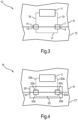
- Fig.3 shows a front view of a section of a household appliance 12 with the door 15 closed.
- the household appliance 12 is designed analogously to the household appliance 1, but has two contact pairs 6, 7 and 13, 14.
- the contact pair 6, 7 is designed as in the household appliance 1, with its immovable contact part 7 also connected to the evaluation circuit 11 via the electrical line 10.
- the second contact pair 13, 14, similarly, has a "third" door contact part 13 and a "fourth" immovable contact part 14, which is arranged in the region of the flange 8.
- Analogous to the first contact pair 6, 7, the door contact part 14 is connected to the evaluation circuit 11 via an electrical line 16.
- the first contact part 6 and the third contact part 13 are electrically connected to one another, for example via metallic components of the door 15 or, as shown, via a dedicated electrical line 17.
- Whether the door 15 is closed is detected by the evaluation circuit 11 by the fact that a current I flows through both (electrically connected in series) contact pairs 6, 7 and 13, 14. If even just one of the contact pairs 6, 7 or 13, 14 is open, no current I flows.
- This exemplary embodiment has the advantage of increasing operational reliability: if the contact pairs 6, 7 and 13, 14 are located, for example, at different corners of the door 15, the case can be taken into account in which a user bends the door open at a corner with force and then the associated contact parts 6, 7 or 13, 14 are separated from one another at least there.
- the door monitoring device has further advantages over the door monitoring device Fig.1 and Fig.2 on:
- the evaluation circuit 11 is connected exclusively to the immovable contact parts 7, 14, so that an electrical line 9 through the door 15 or through metallic components of the door 15 is not necessary.
- Such a current conduction only in the household appliance 1 outside the door 15, provides the following advantages, among others: It is avoided that the current I is conducted directly through the door hinge 3 with its possibly fluctuating electrical resistance, which in turn prevents unreliable contact detection, especially in the case of a mechanically worn door hinge 3.
- Another advantage is that, if an electrical consumer present in the door 15 (e.g., a control panel, not shown) is to be supplied, an unfavorable current routing to the door contact parts 6 and 13 via the door hinge 3 or via a cable 9 in the area of the door hinge 3, which is due to, for example, lack of space, is avoided. Furthermore, a break in the electrical cable 9 due to frequent mechanical stress when opening and closing the door 15 can be ruled out.
- an electrical consumer present in the door 15 e.g., a control panel, not shown
- the door monitoring device here comprises the contact parts 6, 7, 13 and 14, the evaluation circuit 11 and the lines 10, 16 and 17.
- Fig.4 shows a front view of a section of a household appliance 18 with the door 21 closed.
- the door monitoring device has a contact pair 19, 20 with a first door contact part 19 and a stationary contact part 20 which is arranged in the region of the flange 8.
- the immovable contact part 20 has several (here: two) electrically separated contact surfaces 22a, 22b, to which electrical lines 10 and 16 leading to the evaluation device 11 are connected.
- the door contact part 19 acts as an electrical (short-circuit) bridge between the two contact surfaces 22a, 22b, allowing a current I to flow between the contact surfaces 22a, 22b via the door contact part 19. This allows the same advantages as in the household appliance 12 to be achieved even when using only one contact pair 19, 20.
- the function as an electrical bridge can be implemented, for example, by having the contact surfaces 24a, 24b of the door contact part 20 that can be contacted with the contact surfaces 22a, 22b be surface areas of an electrically conductive, e.g., metallic, component, e.g., a metal piece.
- the contact surfaces 24a, 24b can be electrically separated from one another as shown and connected to one another via an electrical line 25.
- the door monitoring device here comprises the contact parts 19 and 20, the evaluation circuit 11 and the connecting lines 10 and 16.
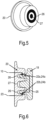
- Fig.5 shows in an oblique view a structural design of one of the two contact parts 19, 20, here the immovable contact part 20, as a plug-in element of a plug-in connection or coupling of the two complementarily shaped contact parts 19, 20.
- the immovable contact part 20 has an annular groove 26 and a central hole 27. In the area of the annular groove 26, the two contact surfaces 22a and 22b are present.
- Fig.6 shows a sectional side view of the two contact parts 19 and 20, which are hidden inside each other when the door is closed.
- the door contact part 19 has a circular rib that can be inserted into the annular groove 26 and a pin-shaped projection that can be inserted into the central hole 27.
- the contact surfaces 22a and 22b are contacted by the contact mating surfaces 24a and 24b, respectively, whereby the contact mating surfaces 24a and 24b are electrically connected to one another, as indicated by the line 25.
- This plug connection or coupling is mechanically particularly stable and enables reliable contact between the contact surfaces 22a and 22b and the contact mating surfaces 24a and 24b, respectively.
- the contact surfaces 22a, 22b can be provided as annular contact surfaces in the annular groove 26, e.g. on opposite side walls.
- One of the One contact surface 22a, 22b may be present in the annular groove 26, and the other of the contact surfaces 22b, 22a may be present in the area of the hole 27.
- the door contact part 19 it is also possible to form the door contact part 19 as a one-piece metal part, so that a dedicated line 25 can be omitted or is formed by the metal part itself.
- the contact mating surfaces 24a and 24b correspond to the surface area of the door contact part 19 that actually comes into contact with the contact surfaces 22a, 22b.
- the shape of the contact parts 19 and 20 can also be exchanged, i.e., the door contact part 19 has the annular groove 26 and the hole 27 and the door contact part 20 has the circular rib and the pin-shaped projection that can be inserted therein.
- the contact pairs can also be used to supply electrical energy to loads located in the door (e.g., operating elements, displays, etc.).
- the loads can be connected to electrical lines 9 or 25 and powered by the current flowing therein.
- the exemplary embodiments depict a single-pole fuse.
- a two-pole fuse can be provided for simple power supplies and a three- or four-pole fuse for three-phase devices. This applies in particular if the contact pair(s) are directly integrated into an electrical circuit for these device components.
Landscapes
- Physics & Mathematics (AREA)
- Electromagnetism (AREA)
- Electric Ovens (AREA)
- Push-Button Switches (AREA)
Claims (13)
- Appareil électroménager (18) à champ électrique pulsé « PEF », présentant une chambre (2) pouvant être fermée au moyen d'une porte (21) ainsi qu'au moins un dispositif de surveillance de porte (11, 19, 20) avec au moins une paire de contacts (19, 20) comprenant deux pièces de contact (19, 20) dont l'une des pièces de contact (19) est disposée sur la porte (21) et l'autre pièce de contact (20) est disposée sur une pièce fixe (8) de l'appareil électroménager (15), dans lequel- au moins la pièce de contact (20) disposée sur la pièce fixe (8) présente plusieurs surfaces de contact (22a, 22b) séparées électriquement les unes des autres et les câbles électriques (10, 16) sont raccordés aux plusieurs surfaces de contact (22a, 22b),- les pièces de contact (19, 20) se contactant lorsque la porte (21) est fermée forment une paire respective de contacts enfichables (22a, 24a, 22b, 24b) et- une première pièce de contact (19) de ces pièces de contact (19, 20) est de forme complémentaire à la deuxième pièce de contact (20) et présente des contre-surfaces de contact (24a, 24b) qui établissent un contact avec les surfaces de contact respectives (22a, 22b) de la deuxième pièce de contact (20), lorsque la porte est fermée,caractérisé en ce que
au moins une deuxième pièce de contact (20) de ces pièces de contact (19, 20) présente une rainure annulaire (26) dans la zone de laquelle est présente au moins une des surfaces de contact (22a, 22b). - Appareil électroménager (18) selon la revendication 1, dans lequel les deux surfaces de contact (22a, 22b) de la deuxième pièce de contact (20) sont disposées sur des sections opposées d'une même paroi latérale de la rainure annulaire (26).
- Appareil électroménager (18) selon la revendication 1, dans lequel les deux surfaces de contact (22a, 22b) de la deuxième pièce de contact (20) sont présentes sous forme de surfaces de contact annulaires disposées sur des parois latérales opposées dans la rainure annulaire (26).
- Appareil électroménager (18) selon l'une des revendications précédentes, dans lequel l'une des pièces de contact (20) présente un trou central (27) en plus de la rainure annulaire (26).
- Appareil électroménager (18) selon la revendication 4, dans lequel la première pièce de contact (19) présente une nervure circulaire pouvant être insérée dans la rainure annulaire (26) et une saillie en forme de broche pouvant être insérée dans le trou central (27).
- Appareil électroménager (18) selon la revendication 1, dans lequel l'une des pièces de contact (20) présente un trou central (27) en plus de la rainure annulaire (26) et dans lequel l'une des surfaces de contact (22a, 22b) de la deuxième pièce de contact (20) est présente dans la rainure annulaire (26) et l'autre des surfaces de contact (22b, 22a) de la deuxième pièce de contact (20) est présente dans la zone du trou (27).
- Appareil électroménager (18) selon l'une des revendications précédentes, dans lequel les surfaces de contact opposées (24a, 24b) de la première pièce de contact (19) sont reliées électriquement entre elles.
- Appareil électroménager (18) selon l'une des revendications précédentes, dans lequel la première pièce de contact (19) est réalisée sous la forme d'une pièce métallique d'un seul tenant.
- Appareil électroménager (1) selon l'une des revendications 1 à 6, dans lequel les deux pièces de contact (6, 7) de la paire de contacts (6, 7) sont reliées chacune à au moins un câble électrique (9, 10), le au moins un câble électrique (9) de la pièce de contact (6) disposée sur la porte (4) est acheminé à travers la porte (4).
- Appareil électroménager (1 ; 18) selon l'une des revendications précédentes, dans lequel l'au moins un dispositif de surveillance de porte (11, 19, 20) présente exactement une paire de contacts (19, 20).
- Appareil électroménager (18) selon l'une des revendications précédentes, dans lequel la pièce fixe (8) est une bride de porte.
- Appareil électroménager (18) selon l'une des revendications précédentes, dans lequel au moins l'une des pièces de contact (19, 20) présente une position de rupture.
- Appareil électroménager (18) selon l'une des revendications précédentes, dans lequel le dispositif de surveillance de porte (11, 19, 20) présente un circuit d'évaluation (11) relié électriquement à au moins l'une des pièces de contact (19, 20) pour surveiller un état d'ouverture des paires de contact (19, 20) correspondantes.
Applications Claiming Priority (2)
| Application Number | Priority Date | Filing Date | Title |
|---|---|---|---|
| DE102020203519.9A DE102020203519A1 (de) | 2020-03-19 | 2020-03-19 | Haushaltsgerät mit Türüberwachungsvorrichtung |
| PCT/EP2021/055270 WO2021185576A1 (fr) | 2020-03-19 | 2021-03-03 | Appareil électroménager comportant un dispositif de surveillance de porte |
Publications (2)
| Publication Number | Publication Date |
|---|---|
| EP4121995A1 EP4121995A1 (fr) | 2023-01-25 |
| EP4121995B1 true EP4121995B1 (fr) | 2025-05-07 |
Family
ID=74859424
Family Applications (1)
| Application Number | Title | Priority Date | Filing Date |
|---|---|---|---|
| EP21710225.0A Active EP4121995B1 (fr) | 2020-03-19 | 2021-03-03 | Appareil électroménager comportant un dispositif de surveillance de porte |
Country Status (5)
| Country | Link |
|---|---|
| US (1) | US12501524B2 (fr) |
| EP (1) | EP4121995B1 (fr) |
| CN (1) | CN115210835A (fr) |
| DE (1) | DE102020203519A1 (fr) |
| WO (1) | WO2021185576A1 (fr) |
Family Cites Families (12)
| Publication number | Priority date | Publication date | Assignee | Title |
|---|---|---|---|---|
| SE391391B (sv) * | 1975-06-12 | 1977-02-14 | Philips Svenska Ab | Sekerhetsanordning vid mikrovagsugn innefattande en av ugnsdorren styrd strombrytare |
| JPS6277001A (ja) | 1985-09-30 | 1987-04-09 | Mitsubishi Electric Corp | 列車モニタリング装置 |
| AU595424B2 (en) * | 1987-02-13 | 1990-03-29 | Maxwell Gervaise Maxwell | Improvements to microwave ovens |
| DE3817075C2 (de) | 1988-05-19 | 1996-09-26 | Miele & Cie | Tür-Sicherheitsschalter für ein Haushaltgerät |
| DE3840650A1 (de) | 1988-12-02 | 1990-06-07 | Vogt Electronic Ag | Elektronische tuersicherung fuer mikrowellengeraete |
| US20090039068A1 (en) | 2007-08-10 | 2009-02-12 | Electrolux Home Products, Inc. | Electric current conduction system for appliance |
| EP2483602B1 (fr) * | 2009-10-02 | 2018-08-22 | BSH Hausgeräte GmbH | Dispositif de porte d'un appareil électroménager, appareil électroménager équipé dudit dispositif de porte et procédé permettant d'actionner un dispositif de porte d'un appareil électroménager |
| DE102010043537A1 (de) | 2010-11-08 | 2012-05-10 | BSH Bosch und Siemens Hausgeräte GmbH | Haushaltsgerät |
| DE102012222152A1 (de) | 2012-12-04 | 2014-06-05 | BSH Bosch und Siemens Hausgeräte GmbH | Türzustandserkennung |
| US20140197161A1 (en) | 2013-01-16 | 2014-07-17 | Standex International Corporation | Door switch apparatus for microwave ovens |
| JP5853155B2 (ja) * | 2013-10-24 | 2016-02-09 | パナソニックIpマネジメント株式会社 | 加熱調理器、調理システム、演算装置及び調理支援方法 |
| CN109413787A (zh) | 2018-10-22 | 2019-03-01 | 惠而浦(中国)股份有限公司 | 自动开关门装置、具有该装置的微波炉及其工作方法 |
-
2020
- 2020-03-19 DE DE102020203519.9A patent/DE102020203519A1/de active Pending
-
2021
- 2021-03-03 EP EP21710225.0A patent/EP4121995B1/fr active Active
- 2021-03-03 CN CN202180021740.1A patent/CN115210835A/zh active Pending
- 2021-03-03 US US17/795,888 patent/US12501524B2/en active Active
- 2021-03-03 WO PCT/EP2021/055270 patent/WO2021185576A1/fr not_active Ceased
Also Published As
| Publication number | Publication date |
|---|---|
| US20230080195A1 (en) | 2023-03-16 |
| US12501524B2 (en) | 2025-12-16 |
| EP4121995A1 (fr) | 2023-01-25 |
| CN115210835A (zh) | 2022-10-18 |
| DE102020203519A1 (de) | 2021-09-23 |
| WO2021185576A1 (fr) | 2021-09-23 |
Similar Documents
| Publication | Publication Date | Title |
|---|---|---|
| DE102019125982B4 (de) | Kombinierte Überwachungsvorrichtung zur Isolationswiderstands- und Schutzleiterwiderstands-Überwachung eines Stromversorgungssystems | |
| EP2850629B1 (fr) | Commutateur électrique | |
| EP2089653B1 (fr) | Procédé et montage permettant une commande fiable d'actionneurs, de capteurs et/ou de récepteurs dans un appareil électro-ménager les contenant | |
| DE102015224658B4 (de) | Elektromechanischer Schutzschalter | |
| EP3782240B1 (fr) | Dispositif et procédé de déconnexion sans charge d'une connexion enfichable | |
| EP4367701B1 (fr) | Disjoncteur | |
| DE69404891T2 (de) | Verbinder mit Kurzschlusskontakt | |
| EP4121995B1 (fr) | Appareil électroménager comportant un dispositif de surveillance de porte | |
| EP1964139B1 (fr) | Appareil de commande dote d'une surveillance des elements de commutation | |
| EP0866480A2 (fr) | Circuit pour l'alimentation d'une charge dans un circuit électrique | |
| EP2638778B1 (fr) | Appareil ménager | |
| WO2006002725A1 (fr) | Dispositif pour deconnecter de maniere fiable un consommateur electrique, notamment une machine electrique | |
| DE3425564A1 (de) | Verriegelungsschalter mit einrichtungen zum verringern der erforderlichen betaetigungskraft | |
| EP2383765B1 (fr) | Relais doté d'une commutation de sécurité intégrée | |
| WO2006069963A1 (fr) | Procede et dispositif pour faire fonctionner un appareil de commutation de maniere sure | |
| WO2020043437A1 (fr) | Four à miro-ondes et procédé pour la sécurisation d'un four à micro-ondes contre un rayonnement micro-ondes sortant d'une chambre de traitement | |
| EP1856451B1 (fr) | Appareil a gaz, en particulier plaque de cuisson a gaz | |
| EP2463584B1 (fr) | Appareil de cuisson | |
| DE102014206360A1 (de) | Verfahren zur Prüfung eines Selbsthaltemagneten eines Schalters und Prüfeinrichtung für den Selbsthaltemagneten | |
| DE102011108447A1 (de) | Verfahren und System zum Erfassen einer Änderung eines Verbindungszustands zweier Verbindungselemente für ein Fahrzeug | |
| BE1029028B1 (de) | Manuell rückstellbare Schaltvorrichtung | |
| DE102012205648B4 (de) | Schutzschaltgerät | |
| DE102016217470B4 (de) | Anordnung zur Erfassung und Abschaltung von Fehlerströmen | |
| DE19917214A1 (de) | Verfahren und Vorrichtung zum Betreiben einer Parallelschaltung | |
| EP3291645A1 (fr) | Four à micro-ondes |
Legal Events
| Date | Code | Title | Description |
|---|---|---|---|
| STAA | Information on the status of an ep patent application or granted ep patent |
Free format text: STATUS: UNKNOWN |
|
| STAA | Information on the status of an ep patent application or granted ep patent |
Free format text: STATUS: THE INTERNATIONAL PUBLICATION HAS BEEN MADE |
|
| PUAI | Public reference made under article 153(3) epc to a published international application that has entered the european phase |
Free format text: ORIGINAL CODE: 0009012 |
|
| STAA | Information on the status of an ep patent application or granted ep patent |
Free format text: STATUS: REQUEST FOR EXAMINATION WAS MADE |
|
| 17P | Request for examination filed |
Effective date: 20221019 |
|
| AK | Designated contracting states |
Kind code of ref document: A1 Designated state(s): AL AT BE BG CH CY CZ DE DK EE ES FI FR GB GR HR HU IE IS IT LI LT LU LV MC MK MT NL NO PL PT RO RS SE SI SK SM TR |
|
| DAV | Request for validation of the european patent (deleted) | ||
| DAX | Request for extension of the european patent (deleted) | ||
| GRAP | Despatch of communication of intention to grant a patent |
Free format text: ORIGINAL CODE: EPIDOSNIGR1 |
|
| STAA | Information on the status of an ep patent application or granted ep patent |
Free format text: STATUS: GRANT OF PATENT IS INTENDED |
|
| INTG | Intention to grant announced |
Effective date: 20241016 |
|
| GRAS | Grant fee paid |
Free format text: ORIGINAL CODE: EPIDOSNIGR3 |
|
| GRAA | (expected) grant |
Free format text: ORIGINAL CODE: 0009210 |
|
| STAA | Information on the status of an ep patent application or granted ep patent |
Free format text: STATUS: THE PATENT HAS BEEN GRANTED |
|
| AK | Designated contracting states |
Kind code of ref document: B1 Designated state(s): AL AT BE BG CH CY CZ DE DK EE ES FI FR GB GR HR HU IE IS IT LI LT LU LV MC MK MT NL NO PL PT RO RS SE SI SK SM TR |
|
| REG | Reference to a national code |
Ref country code: GB Ref legal event code: FG4D Free format text: NOT ENGLISH |
|
| REG | Reference to a national code |
Ref country code: CH Ref legal event code: EP |
|
| REG | Reference to a national code |
Ref country code: DE Ref legal event code: R096 Ref document number: 502021007403 Country of ref document: DE |
|
| REG | Reference to a national code |
Ref country code: IE Ref legal event code: FG4D Free format text: LANGUAGE OF EP DOCUMENT: GERMAN |
|
| REG | Reference to a national code |
Ref country code: NL Ref legal event code: MP Effective date: 20250507 |
|
| PG25 | Lapsed in a contracting state [announced via postgrant information from national office to epo] |
Ref country code: PT Free format text: LAPSE BECAUSE OF FAILURE TO SUBMIT A TRANSLATION OF THE DESCRIPTION OR TO PAY THE FEE WITHIN THE PRESCRIBED TIME-LIMIT Effective date: 20250908 Ref country code: ES Free format text: LAPSE BECAUSE OF FAILURE TO SUBMIT A TRANSLATION OF THE DESCRIPTION OR TO PAY THE FEE WITHIN THE PRESCRIBED TIME-LIMIT Effective date: 20250507 Ref country code: FI Free format text: LAPSE BECAUSE OF FAILURE TO SUBMIT A TRANSLATION OF THE DESCRIPTION OR TO PAY THE FEE WITHIN THE PRESCRIBED TIME-LIMIT Effective date: 20250507 |
|
| REG | Reference to a national code |
Ref country code: LT Ref legal event code: MG9D |
|
| PG25 | Lapsed in a contracting state [announced via postgrant information from national office to epo] |
Ref country code: NO Free format text: LAPSE BECAUSE OF FAILURE TO SUBMIT A TRANSLATION OF THE DESCRIPTION OR TO PAY THE FEE WITHIN THE PRESCRIBED TIME-LIMIT Effective date: 20250807 Ref country code: GR Free format text: LAPSE BECAUSE OF FAILURE TO SUBMIT A TRANSLATION OF THE DESCRIPTION OR TO PAY THE FEE WITHIN THE PRESCRIBED TIME-LIMIT Effective date: 20250808 |
|
| PG25 | Lapsed in a contracting state [announced via postgrant information from national office to epo] |
Ref country code: NL Free format text: LAPSE BECAUSE OF FAILURE TO SUBMIT A TRANSLATION OF THE DESCRIPTION OR TO PAY THE FEE WITHIN THE PRESCRIBED TIME-LIMIT Effective date: 20250507 Ref country code: PL Free format text: LAPSE BECAUSE OF FAILURE TO SUBMIT A TRANSLATION OF THE DESCRIPTION OR TO PAY THE FEE WITHIN THE PRESCRIBED TIME-LIMIT Effective date: 20250507 |
|
| PG25 | Lapsed in a contracting state [announced via postgrant information from national office to epo] |
Ref country code: BG Free format text: LAPSE BECAUSE OF FAILURE TO SUBMIT A TRANSLATION OF THE DESCRIPTION OR TO PAY THE FEE WITHIN THE PRESCRIBED TIME-LIMIT Effective date: 20250507 |
|
| PG25 | Lapsed in a contracting state [announced via postgrant information from national office to epo] |
Ref country code: HR Free format text: LAPSE BECAUSE OF FAILURE TO SUBMIT A TRANSLATION OF THE DESCRIPTION OR TO PAY THE FEE WITHIN THE PRESCRIBED TIME-LIMIT Effective date: 20250507 |
|
| PG25 | Lapsed in a contracting state [announced via postgrant information from national office to epo] |
Ref country code: RS Free format text: LAPSE BECAUSE OF FAILURE TO SUBMIT A TRANSLATION OF THE DESCRIPTION OR TO PAY THE FEE WITHIN THE PRESCRIBED TIME-LIMIT Effective date: 20250807 |
|
| PG25 | Lapsed in a contracting state [announced via postgrant information from national office to epo] |
Ref country code: IS Free format text: LAPSE BECAUSE OF FAILURE TO SUBMIT A TRANSLATION OF THE DESCRIPTION OR TO PAY THE FEE WITHIN THE PRESCRIBED TIME-LIMIT Effective date: 20250907 |
|
| PG25 | Lapsed in a contracting state [announced via postgrant information from national office to epo] |
Ref country code: LV Free format text: LAPSE BECAUSE OF FAILURE TO SUBMIT A TRANSLATION OF THE DESCRIPTION OR TO PAY THE FEE WITHIN THE PRESCRIBED TIME-LIMIT Effective date: 20250507 |
|
| PG25 | Lapsed in a contracting state [announced via postgrant information from national office to epo] |
Ref country code: SM Free format text: LAPSE BECAUSE OF FAILURE TO SUBMIT A TRANSLATION OF THE DESCRIPTION OR TO PAY THE FEE WITHIN THE PRESCRIBED TIME-LIMIT Effective date: 20250507 Ref country code: DK Free format text: LAPSE BECAUSE OF FAILURE TO SUBMIT A TRANSLATION OF THE DESCRIPTION OR TO PAY THE FEE WITHIN THE PRESCRIBED TIME-LIMIT Effective date: 20250507 |
|
| PG25 | Lapsed in a contracting state [announced via postgrant information from national office to epo] |
Ref country code: CZ Free format text: LAPSE BECAUSE OF FAILURE TO SUBMIT A TRANSLATION OF THE DESCRIPTION OR TO PAY THE FEE WITHIN THE PRESCRIBED TIME-LIMIT Effective date: 20250507 |
|
| PG25 | Lapsed in a contracting state [announced via postgrant information from national office to epo] |
Ref country code: EE Free format text: LAPSE BECAUSE OF FAILURE TO SUBMIT A TRANSLATION OF THE DESCRIPTION OR TO PAY THE FEE WITHIN THE PRESCRIBED TIME-LIMIT Effective date: 20250507 |
|
| PG25 | Lapsed in a contracting state [announced via postgrant information from national office to epo] |
Ref country code: SK Free format text: LAPSE BECAUSE OF FAILURE TO SUBMIT A TRANSLATION OF THE DESCRIPTION OR TO PAY THE FEE WITHIN THE PRESCRIBED TIME-LIMIT Effective date: 20250507 |
|
| PG25 | Lapsed in a contracting state [announced via postgrant information from national office to epo] |
Ref country code: IT Free format text: LAPSE BECAUSE OF FAILURE TO SUBMIT A TRANSLATION OF THE DESCRIPTION OR TO PAY THE FEE WITHIN THE PRESCRIBED TIME-LIMIT Effective date: 20250507 |
|
| REG | Reference to a national code |
Ref country code: DE Ref legal event code: R097 Ref document number: 502021007403 Country of ref document: DE |
|
| PLBE | No opposition filed within time limit |
Free format text: ORIGINAL CODE: 0009261 |
|
| STAA | Information on the status of an ep patent application or granted ep patent |
Free format text: STATUS: NO OPPOSITION FILED WITHIN TIME LIMIT |
|
| REG | Reference to a national code |
Ref country code: CH Ref legal event code: L10 Free format text: ST27 STATUS EVENT CODE: U-0-0-L10-L00 (AS PROVIDED BY THE NATIONAL OFFICE) Effective date: 20260318 |
|
| 26N | No opposition filed |
Effective date: 20260210 |