EP4122106B1 - Beseitigung der passiven intermodulation in antennensystemen - Google Patents
Beseitigung der passiven intermodulation in antennensystemen Download PDFInfo
- Publication number
- EP4122106B1 EP4122106B1 EP20925205.5A EP20925205A EP4122106B1 EP 4122106 B1 EP4122106 B1 EP 4122106B1 EP 20925205 A EP20925205 A EP 20925205A EP 4122106 B1 EP4122106 B1 EP 4122106B1
- Authority
- EP
- European Patent Office
- Prior art keywords
- pim
- radio chains
- antenna system
- signal
- transmission
- Prior art date
- Legal status (The legal status is an assumption and is not a legal conclusion. Google has not performed a legal analysis and makes no representation as to the accuracy of the status listed.)
- Active
Links
Images



Classifications
-
- H—ELECTRICITY
- H04—ELECTRIC COMMUNICATION TECHNIQUE
- H04B—TRANSMISSION
- H04B1/00—Details of transmission systems, not covered by a single one of groups H04B3/00 - H04B13/00; Details of transmission systems not characterised by the medium used for transmission
- H04B1/38—Transceivers, i.e. devices in which transmitter and receiver form a structural unit and in which at least one part is used for functions of transmitting and receiving
- H04B1/40—Circuits
- H04B1/50—Circuits using different frequencies for the two directions of communication
- H04B1/52—Hybrid arrangements, i.e. arrangements for transition from single-path two-direction transmission to single-direction transmission on each of two paths or vice versa
- H04B1/525—Hybrid arrangements, i.e. arrangements for transition from single-path two-direction transmission to single-direction transmission on each of two paths or vice versa with means for reducing leakage of transmitter signal into the receiver
-
- H—ELECTRICITY
- H04—ELECTRIC COMMUNICATION TECHNIQUE
- H04B—TRANSMISSION
- H04B7/00—Radio transmission systems, i.e. using radiation field
- H04B7/02—Diversity systems; Multi-antenna system, i.e. transmission or reception using multiple antennas
- H04B7/04—Diversity systems; Multi-antenna system, i.e. transmission or reception using multiple antennas using two or more spaced independent antennas
- H04B7/06—Diversity systems; Multi-antenna system, i.e. transmission or reception using multiple antennas using two or more spaced independent antennas at the transmitting station
- H04B7/0613—Diversity systems; Multi-antenna system, i.e. transmission or reception using multiple antennas using two or more spaced independent antennas at the transmitting station using simultaneous transmission
- H04B7/0615—Diversity systems; Multi-antenna system, i.e. transmission or reception using multiple antennas using two or more spaced independent antennas at the transmitting station using simultaneous transmission of weighted versions of same signal
- H04B7/0617—Diversity systems; Multi-antenna system, i.e. transmission or reception using multiple antennas using two or more spaced independent antennas at the transmitting station using simultaneous transmission of weighted versions of same signal for beam forming
Definitions
- Embodiments presented herein relate to a method, a controller, a computer program, and a computer program product for passive intermodulation removal in an antenna system.
- PIM passive intermodulation
- TX transmission
- RX receiver
- Another way to mitigate PIM is to use the PIM eigen components in the uplink to steer the nulls in the downlink.
- this principle only tries to avoid exciting the PIM source.
- Null steering in the downlink comes with a cost of reduced capacity in terms of total power and spatial steering.
- the complexity of the third order non-linear modeling increases as O ( N 3 ) with respect to the number of antennas N.
- O N 3
- the number of terms will increase to 40.
- 40.4 160 polynomial terms need to be computed and tracked for each time the beam direction of the transmitter is changed.
- Document WO2019220179 relates to a method, a controller, a computer program, and a computer program product for passive intermodulation removal in an antenna system.
- An object of embodiments herein is to provide efficient PIM mitigation, not suffering from the issues noted above, or at least where the above identified issues are reduced or mitigated.
- a method for PIM removal in an antenna system is performed by a controller of the antenna system.
- the method comprises identifying, during transmission using codebook based beamforming, which transmission radio chains of the antenna system that cause a signal received by receiver radio chains of the antenna system to be impacted by PIM. These transmission radio chains are identified based on which codeword in the codebook is used for the beamforming.
- the method comprises determining a correction signal by subjecting the signals only as transmitted by the identified transmission radio chains to a model of the PIM.
- the method comprises removing PIM from the signal received by the receiver radio chains by subtracting the correction signal from the signal received by the receiver radio chains.
- a controller of an antenna system for PIM removal in the antenna system comprises processing circuitry.
- the processing circuitry is configured to cause the controller to identify, during transmission using codebook based beamforming, which transmission radio chains of the antenna system that cause a signal received by receiver radio chains of the antenna system to be impacted by PIM. These transmission radio chains are identified based on which codeword in the codebook is used for the beamforming.
- the processing circuitry is configured to cause the controller to determine a correction signal by subjecting the signals only as transmitted by the identified transmission radio chains to a model of the PIM.
- the processing circuitry is configured to cause the controller to remove PIM from the signal received by the receiver radio chains by subtracting the correction signal from the signal received by the receiver radio chains.
- a controller of an antenna system for PIM removal in the antenna system comprises an identify module configured to identify, during transmission using codebook based beamforming, which transmission radio chains of the antenna system that cause a signal received by receiver radio chains of the antenna system to be impacted by PIM. These transmission radio chains are identified based on which codeword in the codebook is used for the beamforming.
- the controller comprises a determine module configured to determine a correction signal by subjecting the signals only as transmitted by the identified transmission radio chains to a model of the PIM.
- the controller comprises a remove module configured to remove PIM from the signal received by the receiver radio chains by subtracting the correction signal from the signal received by the receiver radio chains.
- a computer program for PIM removal in an antenna system comprising computer program code which, when run on a controller of the antenna system, causes the controller to perform a method according to the first aspect.
- a computer program product comprising a computer program according to the fourth aspect and a computer readable storage medium on which the computer program is stored.
- the computer readable storage medium could be a non-transitory computer readable storage medium.
- these aspects provide efficient PIM mitigation.
- the proposed PIM removal does not suffer from the issues noted above.
- these aspects enable fast tracking and convergence of the PIM model
- these aspects are based on the PIM model coefficients being computed in relation to the beamforming codebook information
- these aspects result in a reduction in computational complexity compared to traditional mechanisms for PIM mitigation.
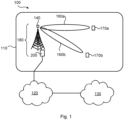
- Fig. 1 is a schematic diagram illustrating a communication network 100 where embodiments presented herein can be applied.
- the communication network 100 could be a third generation (3G) telecommunications network, a fourth generation (4G) telecommunications network, or a fifth (5G) telecommunications network and support any 3GPP telecommunications standard, where applicable.
- the communication network 100 comprises a radio network node 180 configured to provide network access to at least one terminal device 170a, 170b in a radio access network 110.
- the radio access network 110 is operatively connected to a core network 120.
- the core network 120 is in turn operatively connected to a service network 130, such as the Internet.
- the terminal devices 170a, 170b is thereby enabled to, via the radio access network node 180, access services of, and exchange data with, the service network 130.
- the radio access network node 180 comprises, is collocated with, is integrated with, or is in operational communications with, an antenna system 140.
- the antenna system 140 might be an active antenna system.
- the radio access network node 180 (via its antenna system 140) and the terminal devices 170a, 170b are configured to communicate with each other in beams 160a, 160b.
- the antenna system 140 is thus configured for beamformed transmission.
- the communication network 100 further comprises a controller 200. Further aspects of the controller 200 will be disclosed below.
- radio access network nodes 180 are radio base stations, base transceiver stations, Node Bs, evolved Node Bs, g Node Bs, access points, and access nodes, and backhaul nodes.
- terminal devices 170a, 170b are wireless devices, mobile stations, mobile phones, handsets, wireless local loop phones, user equipment (UE), smartphones, laptop computers, tablet computers, network equipped sensors, network equipped vehicles, and so-called Internet of Things devices.
- Fig. 2 schematically illustrates the antenna system 140 of Fig. 1 in more detail.
- the antenna system 140 comprises two transmission radio chains 141 and two receiver radio chains 142.
- the original signals x 0 and x 1 are first weighted by precoding coefficients w in an encoder part 143 to form signals u 0 and u 1 .
- the signals u 0 and u 1 can be used for PIM removal.
- the signals s 0 and s 1 at the receiver side are weighted by decoding coefficients h in a decoder part 152.
- the signals s 0 and s 1 (and also y 0 and/or y 1 ) can be used for PIM removal.
- the values of the precoding coefficients w and the decoding coefficients h are defined by which codeword is used for the beamformed transmission.
- the precoding coefficients are generated by the precoding matrix with the codebook information, i.e. the codebook index is pointed to certain precoding coefficients which have gain and phase information for beamforming in a specific direction.
- Each transmission radio chain 141 in turn comprises components, such as a digital-to-analogue (DAC) converter 144, a power amplifier (PA) 145, a bandpass filter (BPF) 146, and a single or double polarized antenna element 147.
- Each receiver radio chain 142 in turn comprises components, such as a single or double polarized antenna element 148, a BPF 149, a low noise amplifier (LNA) 150, and an analogue-to-digital (ADC) converter 151.
- the skilled person would understand how the antenna system 140 could be extended to comprise more than two transmission radio chains 141 and more than two receiver radio chains 142, such as in an AAS.
- Fig. 2 also schematically illustrates an external PIM source 190.
- Signals transmitted from one or more of the transmission radio chains 141 might thus be (distorted and) reflected by the external PIM source 190 and received by at least one of the receiver radio chains 142, thus causing PIM.
- PIM might be caused by any of the components 143-147 of the transmission radio chain 141. That is, in some embodiments, the PIM is caused by a PIM source 190 external to the antenna system 140 whereas in other embodiments, the PIM is caused by a passive electric component of at least one of the identified transmission radio chains 141.
- the embodiments disclosed herein therefore relate to mechanisms for PIM removal in an antenna system 140.
- a controller 200 of the antenna system 140 a method performed by the controller 200, a computer program product comprising code, for example in the form of a computer program, that when run on a controller 200, causes the controller 200 to perform the method.
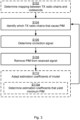
- Fig. 3 is a flowchart illustrating embodiments of methods for PIM removal in an antenna system 140. The methods are performed by the controller 200 of the antenna system 140. The methods are advantageously provided as computer programs 920.
- step S104 The controller 200 identifies, during transmission using codebook based beamforming, which transmission radio chains 141 of the antenna system 140 that cause a signal received by receiver radio chains 142 of the antenna system 140 to be impacted by PIM. These transmission radio chains 141 are identified based on which codeword in the codebook is used for the beamforming.
- the PIM is then mitigated based only on the signals transmitted by the identified transmission radio chains 141. That is, information of the signals as transmitted by any transmission radio chain 141 not having been identified is not utilized for the PIM mitigation.
- the controller 200 is configured to perform step S106: S106: The controller 200 determines a correction signal by subjecting the signals only as transmitted by the identified transmission radio chains 141 to a model of the PIM.
- step S108 The controller 200 removes PIM from the signal received by the receiver radio chains 142 by subtracting the correction signal from the signal received by the receiver radio chains 142.
- PIM is removed from all receiver radio chains 142 whereas in other aspects PIM is removed from only some of the receiver radio chains 142. Particularly, according to an embodiment, PIM is removed from the signal only from those of the receiver radio chains 142 having been identified as being impacted by the PIM. From which of the receiver radio chains 142 PIM needs to be removed can be determined in similar manner as which transmission radio chains 141 are identified as causing the receiver radio chains 142 to be impacted by PIM.
- This mapping can then be used to identify the transmission radio chains 141 that cause the PIM. That is, in some embodiments, this mapping is used to identify those of the transmission radio chains 141 that cause the aforementioned any signal received by the receiver radio chains 142 to be impacted by PIM during transmission using codebook based beamforming.
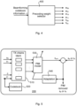
- Fig. 4 schematically illustrates a precoding weight selector 400 that selects precoding coefficients w and decoding coefficients h based on which codeword c is used for the beamforming.
- Each codebook entry, or codeword, used for the precoding provides a pointer to one or more specific PIM aggressors (i.e., to one or more of the transmission radio chains 141).
- PIM aggressors are thus the transmission radio chains 141 which will cause one or more of the receiver radio chains 142 to be impacted by PIM.
- the signals from other transmission radio chains 141 that will not cause PIM will not be used for PIM mitigation purposes. As such, the computation complexity of the PIM removal can be reduced.
- U [ u 0 , u 1 , ..., u K -1 ] denote the signals to the transmitter branches
- c is the codebook index
- M ( c ) is an index function that produces a list of transmitter signals to be used for PIM modelling for a codebook index c
- U ( M ( c )) defines the subset of the signals u 1 , u 1 , ..., u K -1 to be used for modelling, as selected by the index function M.
- the index function M selects k out of all K antenna branches (for example, 4 out of 64 antenna branches) as important for the PIM model, and the function f c is then adapted to match and remove (or even cancel) PIM of a receiver branch optimally using only these inputs.
- the function f c might be separately adapted for each receiver branch and each codebook index (but a similar process could be made to only cancel PIM for a selected few receiver branches if required).
- the index function M is different for each receiver branch.
- the modelled PIM signal x pim (i.e., the correction signal) will hence be subtracted from the received s o or s 1 in Fig. 2 depending on from which receiver radio chain 142 PIM is to be removed (i.e., from s 0 or s 1 ).
- the error from the subtraction can be minimized by adapting the model, resulting in a PIM-free received output signal.
- the processing involves filtering.
- subjecting the signal to the model involves filtering the signal with estimation coefficients of the model defining filter taps.
- filters used for this filtering.
- the signal is filtered using a non-linear filter.
- step S108 PIM is removed from the signal received by the receiver radio chains 142. Removing PIM from the signal received by the receiver radio chains 142 thus yields a PIM removed signal. In this respect, how much PIM that is removed depends on how well the correction signal captures the PIM. In turn, how well the correction signal captures the PIM depends on how well the model captures the PIM.
- a feedback mechanism is introduced by means of which the model is adapted.
- the controller 200 is configured to perform (optional) step S110: S110: The controller 200 adapts estimation coefficients of the model based on how much PIM is still present in the PIM removed signal.
- the estimation coefficients are selected according as the solution to an optimization problem where the object is to minimize the PIM. That is, in some embodiments, the controller 200 is configured to perform (optional) step S110a as part of step S110: S110a: The controller 200 determines which estimation coefficients that per each codeword in the codebook yield minimum PIM for those of the transmitter radio chains that per each codeword cause any signal received by the receiver radio chains 142 to be impacted by PIM.
- Fig. 5 schematically illustrates PIM removal in a controller 200 according to an embodiment.
- codeword c Based on which codeword c is used for the beamforming, those transmission radio chains of the antenna system that cause a signal received by receiver radio chains of the antenna system to be impacted by PIM are identified in TX chains identification block 510.
- the model coefficients are specific for each codeword. That is, in some embodiments, the model has one set of estimation coefficients per each codeword. If a new codeword c' is used for the beamforming, the new codeword c'is added to the codebook 520.
- a correction signal x pim is determined by subjecting the signals only as transmitted by the identified transmission radio chains to the model 530 of the PIM.
- the PIM is then removed from the signal s 0 or s 1 as received by the receiver radio chains by subtracting the correction signal x pim from the signal s 0 or s 1 as received by the receiver radio chains.
- the adaptation block 540 takes as input the PIM removed signal and determines which estimation coefficients that for the used codeword in the codebook yield minimum PIM. The estimation coefficients as adapted are then provided to the model 530.
- Fig. 6 is a flowchart of a method for adapting the model in accordance with embodiments disclosed herein.
- step S202 It is checked whether PIM removal has been performed for the codeword used for the beamforming or if the codeword indicates that the beamforming is in a new direction. If the beamforming is in a new direction step S203 is entered, and else step S204 is entered.
- a correction signal is determined by subjecting the signals only as transmitted by the identified transmission radio chains 141 to a model of the PIM.
- the PIM is modelled based on codebook information, such as which codeword was used for the beamforming. That is, the estimation coefficients of the model are selected dependent on which codeword was used for the beamforming. If the beamforming is in new direction (i.e., step S203 was entered) use default values of the estimation coefficients could be used.
- step S206 It is checked whether a minimum of the error energy has been reached, and hence if the power of the PIM removed signal has been minimized. If yes, step S207 is entered, and else step S208 is entered.
- S207 The estimation coefficients of the model are stored for later use when beamforming using the same codeword is performed.
- Step S208 The estimation coefficients of the model are adapted based on how much PIM is still present in the PIM removed signal. Step S204 is then entered again where the estimation coefficients as adapted in step S208 are used when determining the correction signal.
- how many transmission radio chains 141 that are to be considered by the model depends on how many transmission radio chains 141 there are in total in the antenna system 140. For example, if the total number of transmission radio chains 141 is comparatively high, only a small fraction of all the transmission radio chains 141 might be considered by the model whereas if the total number of transmission radio chains 141 is comparatively low, a large fraction of all the transmission radio chains 141 might be considered by the model in order to keep a reasonable level of complexity and computational cost at the controller 200. That is, in some embodiments, how many transmission radio chains 141 that are to be identified in step S104 is dependent on how many transmission radio chains 141 there are in total.
- how many transmission radio chains 141 that are to be considered by the model depends on the amount of PIM caused. In particular, in some embodiments, how many transmission radio chains 141 that are to be identified in step S104 is dependent on how much, or how many of, the receiver radio chains 142 are impacted by the PIM. In this respect, for a comparatively high level of PIM, more transmission radio chains 141 might be considered by the model than for only a comparatively low level of PIM. The design of the PIM model could thereby be adapted to handle different levels of PIM in an efficient manner.
- a fixed amount of transmission radio chains 141 are considered by the model. That is, in some embodiments, at most a predefined number of all transmission radio chains 141 are identified in in step S104. This might enable an efficient implementation of the PIM model since it could be designed for one particular number of transmission radio chains 141.
- Fig. 7 schematically illustrates, in terms of a number of functional units, the components of a controller 200 according to an embodiment.
- Processing circuitry 210 is provided using any combination of one or more of a suitable central processing unit (CPU), multiprocessor, microcontroller, digital signal processor (DSP), etc., capable of executing software instructions stored in a computer program product 910 (as in Fig. 9 ), e.g. in the form of a storage medium 230.
- the processing circuitry 210 may further be provided as at least one application specific integrated circuit (ASIC), or field programmable gate array (FPGA).
- ASIC application specific integrated circuit
- FPGA field programmable gate array
- the processing circuitry 210 is configured to cause the controller 200 to perform a set of operations, or steps, as disclosed above.
- the storage medium 230 may store the set of operations
- the processing circuitry 210 may be configured to retrieve the set of operations from the storage medium 230 to cause the controller 200 to perform the set of operations.
- the set of operations may be provided as a set of executable instructions.
- the processing circuitry 210 is thereby arranged to execute methods as herein disclosed.
- the storage medium 230 may also comprise persistent storage, which, for example, can be any single one or combination of magnetic memory, optical memory, solid state memory or even remotely mounted memory.
- the controller 200 may further comprise a communications interface 220 at least configured for communications with the antenna system 140. As such the communications interface 220 may comprise one or more transmitters and receivers, comprising analogue and digital components.
- the processing circuitry 210 controls the general operation of the controller 200 e.g. by sending data and control signals to the communications interface 220 and the storage medium 230, by receiving data and reports from the communications interface 220, and by retrieving data and instructions from the storage medium 230.
- Other components, as well as the related functionality, of the controller 200 are omitted in order not to obscure the concepts presented herein.
- Fig. 8 schematically illustrates, in terms of a number of functional modules, the components of a controller 200 according to an embodiment.
- the controller 200 of Fig. 8 comprises a number of functional modules; an identify module 210b configured to perform step S104, a determine module 210c configured to perform step S106, and a remove module 210d configured to perform step S108.
- the controller 200 of Fig. 8 may further comprise a number of optional functional modules, such as any of a determine module 210a configured to perform step S210a, an adapt module 210e configured to perform step S110, and a determine module 210f configured to perform step Sna.
- each functional module 210a-210f may in one embodiment be implemented only in hardware and in another embodiment with the help of software, i.e., the latter embodiment having computer program instructions stored on the storage medium 230 which when run on the processing circuitry makes the controller 200 perform the corresponding steps mentioned above in conjunction with Fig 8 .
- the modules correspond to parts of a computer program, they do not need to be separate modules therein, but the way in which they are implemented in software is dependent on the programming language used.
- one or more or all functional modules 210a-210f may be implemented by the processing circuitry 210, possibly in cooperation with the communications interface 220 and/or the storage medium 230.
- the processing circuitry 210 may thus be configured to from the storage medium 230 fetch instructions as provided by a functional module 210a-210f and to execute these instructions, thereby performing any steps as disclosed herein.
- the controller 200 may be provided as a standalone device or as a part of at least one further device.
- the controller 200 may be provided in a node of the radio access network and might be part of, integrated with, or collocated with, the antenna system 140.
- functionality of the controller 200 may be distributed between at least two devices, or nodes.
- a first portion of the instructions performed by the controller 200 may be executed in a first device
- a second portion of the of the instructions performed by the controller 200 may be executed in a second device; the herein disclosed embodiments are not limited to any particular number of devices on which the instructions performed by the controller 200 may be executed.
- the methods according to the herein disclosed embodiments are suitable to be performed by a controller 200 residing in a cloud computational environment.
- processing circuitry 210 may be distributed among a plurality of devices, or nodes. The same applies to the functional modules 210a-210f of Fig. 8 and the computer program 920 of Fig. 9 .
- Fig. 9 shows one example of a computer program product 910 comprising computer readable storage medium 930.
- a computer program 920 can be stored, which computer program 920 can cause the processing circuitry 210 and thereto operatively coupled entities and devices, such as the communications interface 220 and the storage medium 230, to execute methods according to embodiments described herein.
- the computer program 920 and/or computer program product 910 may thus provide means for performing any steps as herein disclosed.
- the computer program product 910 is illustrated as an optical disc, such as a CD (compact disc) or a DVD (digital versatile disc) or a Blu-Ray disc.
- the computer program product 910 could also be embodied as a memory, such as a random access memory (RAM), a read-only memory (ROM), an erasable programmable read-only memory (EPROM), or an electrically erasable programmable read-only memory (EEPROM) and more particularly as a non-volatile storage medium of a device in an external memory such as a USB (Universal Serial Bus) memory or a Flash memory, such as a compact Flash memory.
- the computer program 920 is here schematically shown as a track on the depicted optical disk, the computer program 920 can be stored in any way which is suitable for the computer program product 910.
Landscapes
- Engineering & Computer Science (AREA)
- Computer Networks & Wireless Communication (AREA)
- Signal Processing (AREA)
- Radio Transmission System (AREA)
Claims (15)
- Verfahren zur Beseitigung von passiver Intermodulation, PIM, in einem Antennensystem (140), wobei das Verfahren von einer Steuereinheit (200) des Antennensystems (140) ausgeführt wird, wobei das Verfahren umfasst:Identifizieren (S104), während einer Übertragung unter Verwendung von Codebuch-basierter Strahlenbildung, welche Übertragungsfunkketten (141) des Antennensystems (140), die ein Signal, das von Empfängerfunkketten (142) des Antennensystems (140) empfangen wird, veranlassen, von PIM beeinflusst zu werden, wobei diese Übertragungsfunkketten (141) basierend darauf identifiziert werden, welches Codewort in dem Codebuch zur Strahlenbildung verwendet wird;Bestimmen (S106) eines Korrektursignals, indem nur die von den identifizierten Übertragungsfunkketten (141) übertragenen Signale einem Modell der PIM unterzogen werden; undBeseitigen (S108) von PIM aus dem von den Empfängerfunkketten (142) empfangenen Signal durch Subtrahieren des Korrektursignals von dem von den Empfängerfunkketten (142) empfangenen Signal.
- Verfahren nach Anspruch 1, wobei das Unterziehen des Signals dem Modell das Filtern des Signals mit Schätzungskoeffizienten des Modells einbezieht, welche Filterabgriffe definieren.
- Verfahren nach Anspruch 2, wobei das Signal unter Verwendung eines nichtlinearen Filters gefiltert wird.
- Verfahren nach einem der vorstehenden Ansprüche, wobei Beseitigen von PIM aus dem von den Empfängerfunkketten (142) empfangenen Signal ein von PIM befreites Signal ergibt, wobei das Verfahren weiter umfasst:
Anpassen (S110) von Schätzungskoeffizienten des Modells basierend darauf, wie viel PIM noch in dem von PIM befreiten Signal vorhanden ist. - Verfahren nach Anspruch 4, wobei das Verfahren weiter umfasst:
Bestimmen (S110a), welche Schätzungskoeffizienten, die jeweils pro Codewort in dem Codebuch minimale PIM für diejenigen der Übertragungsfunkketten ergeben, die jeweils pro Codewort jedes von den Empfängerfunkketten (142) empfangene Signal veranlasst, durch PIM beeinflusst zu werden. - Verfahren nach einem der vorstehenden Ansprüche, wobei das Modell einen Satz an Schätzungskoeffizienten für jedes Codewort aufweist.
- Verfahren nach einem der vorstehenden Ansprüche, wobei das Verfahren weiter umfasst:
Bestimmen (S102) einer Zuordnung zwischen Übertragungsfunkketten (141) und Codewörtern durch Identifizieren, welche der Übertragungsfunkketten (141), die für jedes Codewort in dem Codebuch jedes von den Empfängerfunkketten (142) des Antennensystems (140) empfangene Signal veranlassen, von PIM beeinflusst zu werden. - Verfahren nach Anspruch 7, wobei die Zuordnung verwendet wird, um diejenigen der Übertragungsfunkketten (141) zu identifizieren, die jedes von den Empfängerfunkketten (142) empfangene Signal veranlassen, während der Übertragung unter Verwendung einer Codebuch-basierten Strahlenbildung durch PIM beeinflusst zu werden.
- Verfahren nach einem der vorstehenden Ansprüche, wobei die Anzahl der zu identifizierenden Übertragungsfunkketten (141) davon abhängt, wie viele Übertragungsfunkketten (141) insgesamt vorhanden sind.
- Verfahren nach einem der Ansprüche 1 bis 8, wobei die Anzahl der zu identifizierenden Übertragungsfunkketten (141) davon abhängt, wie viel die oder wie viele der Empfängerfunkketten (142) von der PIM beeinflusst werden.
- Verfahren nach einem der vorstehenden Ansprüche, wobei höchstens eine vordefinierte Anzahl aller Übertragungsfunkketten (141) identifiziert wird.
- Verfahren nach einem der vorstehenden Ansprüche, wobei PIM nur aus dem Signal der Empfängerfunkketten (142) beseitigt wird, welche als von der PIM beeinflusst identifiziert wurden.
- Steuereinheit (200) eines Antennensystems (140) zur Beseitigung von passiver Intermodulation, PIM, in dem Antennensystem (140), wobei die Steuereinheit (200) eine Verarbeitungsschaltung (210) umfasst, wobei die Verarbeitungsschaltung konfiguriert ist, um die Steuereinheit (200) zu veranlassen:während Übertragung unter Verwendung von Codebuch-basierter Strahlenbildung zu identifizieren, welche Übertragungsfunkketten (141) des Antennensystems (140), die ein Signal, das von Empfängerfunkketten (142) des Antennensystems (140) empfangen wird, veranlassen, von PIM beeinflusst zu werden, wobei diese Übertragungsfunkketten (141) basierend darauf identifiziert werden, welches Codewort in dem Codebuch zur Strahlenbildung verwendet wird;ein Korrektursignal zu bestimmen, indem nur die von den identifizierten Übertragungsfunkketten (141) übertragenen Signale einem Modell der PIM unterzogen werden; undPIM aus dem von den Empfängerfunkketten (142) empfangenen Signal durch Subtrahieren des Korrektursignals von dem von den Empfängerfunkketten (142) empfangenen Signal zu beseitigen.
- Computerprogramm (920) zur Beseitigung von passiver Intermodulation, PIM, in einem Antennensystem (140), wobei das Computerprogramm Computercode umfasst, welcher, wenn er in einer Verarbeitungsschaltung (210) einer Steuereinheit (200) des Antennensystems (140) läuft, die Steuereinheit (200) veranlasst:während der Übertragung unter Verwendung von Codebuch-basierter Strahlenbildung zu identifizieren (S104), welche Übertragungsfunkketten (141) des Antennensystems (140), die ein Signal, das von Empfängerfunkketten (142) des Antennensystems (140) empfangen wird, veranlassen, von PIM beeinflusst zu werden, wobei diese Übertragungsfunkketten (141) basierend darauf identifiziert werden, welches Codewort in dem Codebuch zur Strahlenbildung verwendet wird;ein Korrektursignal zu bestimmen (S106), indem nur die von den identifizierten Übertragungsfunkketten (141) übertragenen Signale einem Modell der PIM unterzogen werden; undPIM aus dem von den Empfängerfunkketten (142) empfangenen Signal durch Subtrahieren des Korrektursignals von dem von den Empfängerfunkketten (142) empfangenen Signal zu beseitigen (S108).
- Computerprogrammprodukt (910), das ein Computerprogramm (920) nach Anspruch 14 und ein computerlesbares Speichermedium (930) umfasst, auf dem das Computerprogramm gespeichert ist.
Applications Claiming Priority (1)
| Application Number | Priority Date | Filing Date | Title |
|---|---|---|---|
| PCT/CN2020/079862 WO2021184232A1 (en) | 2020-03-18 | 2020-03-18 | Removal of passive intermodulation in antenna systems |
Publications (3)
| Publication Number | Publication Date |
|---|---|
| EP4122106A1 EP4122106A1 (de) | 2023-01-25 |
| EP4122106A4 EP4122106A4 (de) | 2023-12-27 |
| EP4122106B1 true EP4122106B1 (de) | 2024-10-23 |
Family
ID=77768360
Family Applications (1)
| Application Number | Title | Priority Date | Filing Date |
|---|---|---|---|
| EP20925205.5A Active EP4122106B1 (de) | 2020-03-18 | 2020-03-18 | Beseitigung der passiven intermodulation in antennensystemen |
Country Status (4)
| Country | Link |
|---|---|
| US (1) | US11996879B2 (de) |
| EP (1) | EP4122106B1 (de) |
| CN (1) | CN115244858B (de) |
| WO (1) | WO2021184232A1 (de) |
Families Citing this family (13)
| Publication number | Priority date | Publication date | Assignee | Title |
|---|---|---|---|---|
| CN115244858B (zh) * | 2020-03-18 | 2025-01-28 | 瑞典爱立信有限公司 | 用于天线系统中无源互调的移除的方法和设备 |
| US12047127B2 (en) | 2020-08-28 | 2024-07-23 | Isco International, Llc | Method and system for mitigating interference in the near field |
| US11502404B1 (en) | 2022-03-31 | 2022-11-15 | Isco International, Llc | Method and system for detecting interference and controlling polarization shifting to mitigate the interference |
| US11476585B1 (en) | 2022-03-31 | 2022-10-18 | Isco International, Llc | Polarization shifting devices and systems for interference mitigation |
| US11509072B1 (en) | 2022-05-26 | 2022-11-22 | Isco International, Llc | Radio frequency (RF) polarization rotation devices and systems for interference mitigation |
| US11515652B1 (en) | 2022-05-26 | 2022-11-29 | Isco International, Llc | Dual shifter devices and systems for polarization rotation to mitigate interference |
| US11509071B1 (en) | 2022-05-26 | 2022-11-22 | Isco International, Llc | Multi-band polarization rotation for interference mitigation |
| US11984919B2 (en) * | 2022-10-03 | 2024-05-14 | Xilinx, Inc. | PIM cancellation architecture |
| US11990976B2 (en) | 2022-10-17 | 2024-05-21 | Isco International, Llc | Method and system for polarization adaptation to reduce propagation loss for a multiple-input-multiple-output (MIMO) antenna |
| US11949489B1 (en) | 2022-10-17 | 2024-04-02 | Isco International, Llc | Method and system for improving multiple-input-multiple-output (MIMO) beam isolation via alternating polarization |
| US12301298B1 (en) | 2023-12-29 | 2025-05-13 | Isco International, Llc | Methods and systems for locating interference sources via angle of arrival (AoA) |
| US12301315B1 (en) | 2023-12-29 | 2025-05-13 | Isco International, Llc | Methods and systems for detecting, measuring, and/or locating passive intermodulation sources via downlink (DL) signal injection |
| US12348285B1 (en) * | 2023-12-29 | 2025-07-01 | Isco International, Llc | Methods and systems for detecting, measuring, and/or locating passive intermodulation (PIM) sources via beamforming |
Family Cites Families (62)
| Publication number | Priority date | Publication date | Assignee | Title |
|---|---|---|---|---|
| US6081536A (en) * | 1997-06-20 | 2000-06-27 | Tantivy Communications, Inc. | Dynamic bandwidth allocation to transmit a wireless protocol across a code division multiple access (CDMA) radio link |
| CN102291222B (zh) | 2010-06-21 | 2014-07-09 | 电信科学技术研究院 | 一种反馈预编码矩阵指示方法、装置及系统 |
| EP2676510A1 (de) * | 2011-02-15 | 2013-12-25 | Telefonaktiebolaget L M Ericsson (PUBL) | Erster netzwerkknoten und zweiter netzwerkknoten sowie verfahren darin |
| EP2710740A1 (de) * | 2011-05-20 | 2014-03-26 | Telefonaktiebolaget LM Ericsson (PUBL) | Dynamische unterdrückung von passiver intermodulationsinterferenz |
| GB2510997B (en) * | 2012-05-21 | 2014-11-05 | Aceaxis Ltd | Detection of Intermodulation Products in a Wireless Network |
| US8855175B2 (en) * | 2012-08-02 | 2014-10-07 | Telefonaktiebolaget L M Ericsson (Publ) | Low complexity all-digital PIM compensator |
| US8890619B2 (en) * | 2012-08-02 | 2014-11-18 | Telefonaktiebolaget L M Ericsson (Publ) | PIM compensation in a receiver |
| CN103002493B (zh) | 2012-12-11 | 2015-05-27 | 华为技术有限公司 | 无源互调检测方法和装置 |
| CN103973351B (zh) * | 2013-02-05 | 2017-12-22 | 华为技术有限公司 | 一种无线通信系统中使用码本进行通信的方法及基站 |
| US20140292609A1 (en) * | 2013-04-02 | 2014-10-02 | Dielectric, Llc | Device and Process for Reduction of Passive Intermodulation |
| US9660673B2 (en) * | 2013-06-26 | 2017-05-23 | Telefonaktiebolaget Lm Ericsson (Publ) | Apparatus and method for canceling inter-modulation products |
| JP5431609B1 (ja) * | 2013-07-09 | 2014-03-05 | ソフトバンクモバイル株式会社 | 基地局、干渉抑圧装置及び干渉抑圧方法 |
| EP2884668B1 (de) * | 2013-12-12 | 2020-11-18 | Nokia Solutions and Networks Oy | Verbesserung der Empfängerempfindlichkeit |
| US9461697B2 (en) * | 2014-02-27 | 2016-10-04 | Scintera Networks Llc | In-service monitoring and cancellation of passive intermodulation interferences |
| CA2946965C (en) * | 2014-05-01 | 2018-03-27 | Mark William WYVILLE | Passive intermodulation detection |
| CN103986482B (zh) * | 2014-05-27 | 2016-02-03 | 北京理工大学 | 一种基于自适应滤波的无源互调干扰抑制方法 |
| MY182790A (en) * | 2014-07-14 | 2021-02-05 | Ericsson Telefon Ab L M | Cancelling crosstalk |
| CN104283580B (zh) * | 2014-09-30 | 2016-09-28 | 上海华为技术有限公司 | 射频模块的无源互调pim干扰抵消方法及相关装置 |
| US10039022B2 (en) * | 2015-06-09 | 2018-07-31 | At&T Intellectual Property I, L.P. | Remote diagnosis and cancellation of passive intermodulation |
| KR102365600B1 (ko) * | 2015-06-09 | 2022-02-21 | 삼성전자주식회사 | 위치 정보 송수신을 위한 방법 및 장치 |
| WO2017006155A1 (en) * | 2015-07-08 | 2017-01-12 | Telefonaktiebolaget Lm Ericsson (Publ) | Uplink spectrum analysis technique for passive intermodulation (pim) detection |
| US10778265B2 (en) * | 2015-10-26 | 2020-09-15 | Telefonaktiebolaget Lm Ericsson (Publ) | Cell site passive intermodulation detection receiver |
| US20170141807A1 (en) * | 2015-11-12 | 2017-05-18 | Futurewei Technologies, Inc. | High Performance PIM Cancellation With Feedback |
| US20170141938A1 (en) * | 2015-11-12 | 2017-05-18 | Futurewei Technologies, Inc. | High Performance PIM Cancellation With Feed Forward Structure |
| US10686424B2 (en) * | 2015-11-12 | 2020-06-16 | Telefonaktiebolaget Lm Ericsson (Publ) | Duplexer |
| WO2017093784A1 (en) * | 2015-12-01 | 2017-06-08 | Telefonaktiebolaget Lm Ericsson (Publ) | Methods and devices for addressing passive intermodulation in wireless communication |
| WO2017157464A1 (en) * | 2016-03-18 | 2017-09-21 | Telefonaktiebolaget Lm Ericsson (Publ) | Methods of handling inter-modulation products interference at a network node or at a co-located network node site |
| US11109386B2 (en) * | 2016-03-18 | 2021-08-31 | Telefonaktiebolaget Lm Ericsson (Publ) | Method and apparatus for handling interference caused by inter-modulation |
| GB2551695B (en) * | 2016-06-07 | 2019-11-27 | Aceaxis Ltd | Mitigating Passive Intermodulation Interference in a MIMO Wireless Network |
| US9768812B1 (en) * | 2016-06-10 | 2017-09-19 | At&T Intellectual Property I, L.P. | Facilitation of passive intermodulation cancellation |
| WO2017220104A1 (en) * | 2016-06-20 | 2017-12-28 | Telefonaktiebolaget Lm Ericsson (Publ) | A wireless communication network node arranged for reduction of passive intermodulation |
| WO2018026316A1 (en) * | 2016-08-01 | 2018-02-08 | Telefonaktiebolaget Lm Ericsson (Publ) | Pim suppression |
| US10651885B2 (en) * | 2016-09-21 | 2020-05-12 | Telefonaktiebolaget Lm Ericsson (Publ) | PIM compensation at a transmitter's radio frequency port |
| EP3509223B1 (de) * | 2016-09-30 | 2023-02-22 | Huawei Technologies Co., Ltd. | Verfahren und vorrichtung zum abbrechen von passiver intermodulation (pim) und basisstation |
| WO2018076373A1 (zh) * | 2016-10-31 | 2018-05-03 | 华为技术有限公司 | 一种塔顶设备及无源互调消除方法 |
| KR102635791B1 (ko) * | 2016-12-21 | 2024-02-08 | 인텔 코포레이션 | 무선 통신 기술, 장치 및 방법 |
| US11056778B2 (en) * | 2017-04-26 | 2021-07-06 | Telefonaktiebolaget Lm Ericsson (Publ) | Radio assembly with modularized radios and interconnects |
| US10141961B1 (en) * | 2017-05-18 | 2018-11-27 | Nanosemi, Inc. | Passive intermodulation cancellation |
| WO2018219435A1 (en) * | 2017-05-30 | 2018-12-06 | Telefonaktiebolaget Lm Ericsson (Publ) | Beam selection for a radio transceiver device |
| KR20200021947A (ko) * | 2017-06-02 | 2020-03-02 | 인텔 아이피 코포레이션 | 뉴 라디오(nr)를 위한 빔포밍된 측정 |
| JP2018207321A (ja) * | 2017-06-06 | 2018-12-27 | 富士通株式会社 | キャンセル装置、キャンセル方法、および無線通信装置 |
| US10187098B1 (en) * | 2017-06-30 | 2019-01-22 | At&T Intellectual Property I, L.P. | Facilitation of passive intermodulation cancelation via machine learning |
| CN107453782A (zh) | 2017-08-23 | 2017-12-08 | 北京银河信通科技有限公司 | 一种基于双时延估计的无源互调干扰对消系统及方法 |
| US10805130B2 (en) * | 2017-09-12 | 2020-10-13 | Intel IP Corporation | Signal cancellation system and method |
| KR102102059B1 (ko) * | 2017-11-30 | 2020-04-17 | 연세대학교 산학협력단 | 자기간섭을 제거할 수 있는 전이중 통신 단말 및 이의 자기간섭 제거 방법 |
| EP3720010A4 (de) * | 2018-01-19 | 2020-10-21 | Huawei Technologies Co., Ltd. | Verfahren zur übertragung von informationen, verfahren zur informationsaufnahme, sendevorrichtung und empfangsvorrichtung |
| CN108777585B (zh) * | 2018-02-09 | 2020-07-10 | 香港梵行科技有限公司 | 一种自适应抵消无线收发系统中无源互调信号的装置及方法 |
| WO2019220180A1 (en) * | 2018-05-16 | 2019-11-21 | Telefonaktiebolaget Lm Ericsson (Publ) | Radiation pattern modification in the presence of interference sources in frequency division duplex (fdd) systems |
| US11589361B2 (en) * | 2018-05-16 | 2023-02-21 | Telefonaktiebolaget Lm Ericsson (Publ) | Uplink-downlink co-scheduling with beam control and passive intermodulation awareness |
| WO2019239196A1 (en) * | 2018-06-15 | 2019-12-19 | Telefonaktiebolaget Lm Ericsson (Publ) | Link-adaptation for passive intermodulation avoidance |
| WO2019245533A1 (en) * | 2018-06-19 | 2019-12-26 | Nokia Solutions And Networks Oy | Estmating a delay |
| US10924141B2 (en) * | 2018-07-15 | 2021-02-16 | Ubiqam Ltd. | Systems and methods for cancellation of passive intermodulation (PIM) for a wireless network receiver |
| CN209001952U (zh) * | 2018-09-27 | 2019-06-18 | 香港梵行科技有限公司 | 一种自适应抵消无源互调信号的装置 |
| CN209088944U (zh) * | 2018-09-27 | 2019-07-09 | 香港梵行科技有限公司 | 自适应抵消无源互调信号的装置 |
| CN109495127B (zh) * | 2018-09-27 | 2021-09-03 | 香港梵行科技有限公司 | 自适应抵消无源互调信号的装置、方法及应用设备 |
| WO2020113928A1 (zh) * | 2018-09-29 | 2020-06-11 | 香港梵行科技有限公司 | 自适应抵消无源互调信号的装置及其方法 |
| CN208955159U (zh) * | 2018-11-21 | 2019-06-07 | 瑞典爱立信有限公司 | 无源交调特性的调节结构以及无线电器件 |
| EP3949129B1 (de) | 2019-04-01 | 2023-01-04 | Telefonaktiebolaget Lm Ericsson (Publ) | Netzwerkvorrichtung und verfahren zur handhabung von passiven intermodulationssignalen in einem drahtlosen kommunikationsnetz |
| EP4104302A1 (de) * | 2020-02-10 | 2022-12-21 | Nokia Solutions and Networks Oy | Passive intermodulationsbewusste strahlformung |
| CN115244858B (zh) * | 2020-03-18 | 2025-01-28 | 瑞典爱立信有限公司 | 用于天线系统中无源互调的移除的方法和设备 |
| US12047127B2 (en) * | 2020-08-28 | 2024-07-23 | Isco International, Llc | Method and system for mitigating interference in the near field |
| EP4399806A1 (de) * | 2021-09-10 | 2024-07-17 | Telefonaktiebolaget LM Ericsson (publ) | Verfahren und system zur iterativen passiven downlink-intermodulationsraumvermeidung |
-
2020
- 2020-03-18 CN CN202080098638.7A patent/CN115244858B/zh active Active
- 2020-03-18 US US17/911,705 patent/US11996879B2/en active Active
- 2020-03-18 WO PCT/CN2020/079862 patent/WO2021184232A1/en not_active Ceased
- 2020-03-18 EP EP20925205.5A patent/EP4122106B1/de active Active
Also Published As
| Publication number | Publication date |
|---|---|
| CN115244858B (zh) | 2025-01-28 |
| EP4122106A4 (de) | 2023-12-27 |
| WO2021184232A9 (en) | 2021-11-11 |
| US20230179252A1 (en) | 2023-06-08 |
| EP4122106A1 (de) | 2023-01-25 |
| US11996879B2 (en) | 2024-05-28 |
| CN115244858A (zh) | 2022-10-25 |
| WO2021184232A1 (en) | 2021-09-23 |
Similar Documents
| Publication | Publication Date | Title |
|---|---|---|
| US11996879B2 (en) | Removal of passive intermodulation in antenna systems | |
| US11956001B2 (en) | Millimeter wave (mmWave) system and methods | |
| WO2017041858A1 (en) | Request of and feedback information for simultaneous wireless information and power transfer for multiple wireless devices | |
| US9794090B2 (en) | Transmitter and interference cancellation method | |
| EP2357768A1 (de) | MIMO-Systeme und Verfahren für drahtlose Kommunikation damit zur Verringerung des Quantisierungseffekts von Vorkodierungsvorgängen unter Verwendung eines endlichen Kodebuches | |
| EP4302405B1 (de) | System und verfahren zur abtastung von signalen | |
| WO2020239214A1 (en) | Controlling total average transmission power of a radio base station | |
| EP3949145A1 (de) | Eirp-steuerung einer funkbasisstation | |
| CN113169804B (zh) | 受损天线分支的处置 | |
| EP3619817B1 (de) | Strahlformung basierend auf kombinierten strahlen | |
| CN114070355B (zh) | 用于消除自干扰信号的电子设备及其操作方法 | |
| US20200059256A1 (en) | Low complexity mimo digital pre-distortion | |
| US20170208598A1 (en) | Distortion cancel device and distortion cancel method | |
| WO2020125526A1 (zh) | 自激抵消方法、装置和系统 | |
| US20150205758A1 (en) | Arithmetic device, arithmetic method, and wireless communication device | |
| US20230216451A1 (en) | Linearization of a non-linear electronic device | |
| US20160380666A1 (en) | Transceiver device and method of processing signals | |
| US10498386B2 (en) | Interference suppression in a radio transceiver device | |
| RU2632417C2 (ru) | Способ, система и устройство предварительного кодирования | |
| CN119986730B (zh) | 导航信号校正方法、装置、设备、介质、产品和芯片系统 | |
| WO2021155493A1 (en) | Method for mitigating passive intermodulation and an apparatus therefor | |
| US20230013213A1 (en) | Candidate beam selection for a terminal device | |
| CN112803976A (zh) | 大规模mimo预编码方法、系统以及电子设备 | |
| US12633962B2 (en) | Full-duplex digital self-interference clear method and apparatus | |
| CN108988935A (zh) | 非线性功放约束下的星地协同信号传输方法及装置 |
Legal Events
| Date | Code | Title | Description |
|---|---|---|---|
| STAA | Information on the status of an ep patent application or granted ep patent |
Free format text: STATUS: THE INTERNATIONAL PUBLICATION HAS BEEN MADE |
|
| PUAI | Public reference made under article 153(3) epc to a published international application that has entered the european phase |
Free format text: ORIGINAL CODE: 0009012 |
|
| STAA | Information on the status of an ep patent application or granted ep patent |
Free format text: STATUS: REQUEST FOR EXAMINATION WAS MADE |
|
| 17P | Request for examination filed |
Effective date: 20220628 |
|
| AK | Designated contracting states |
Kind code of ref document: A1 Designated state(s): AL AT BE BG CH CY CZ DE DK EE ES FI FR GB GR HR HU IE IS IT LI LT LU LV MC MK MT NL NO PL PT RO RS SE SI SK SM TR |
|
| DAV | Request for validation of the european patent (deleted) | ||
| DAX | Request for extension of the european patent (deleted) | ||
| REG | Reference to a national code |
Ref country code: DE Free format text: PREVIOUS MAIN CLASS: H04B0001520000 Ipc: H04B0001525000 Ref legal event code: R079 Ref document number: 602020040104 Country of ref document: DE |
|
| A4 | Supplementary search report drawn up and despatched |
Effective date: 20231123 |
|
| RIC1 | Information provided on ipc code assigned before grant |
Ipc: H04B 7/06 20060101ALI20231117BHEP Ipc: H04B 1/525 20150101AFI20231117BHEP |
|
| GRAP | Despatch of communication of intention to grant a patent |
Free format text: ORIGINAL CODE: EPIDOSNIGR1 |
|
| STAA | Information on the status of an ep patent application or granted ep patent |
Free format text: STATUS: GRANT OF PATENT IS INTENDED |
|
| INTG | Intention to grant announced |
Effective date: 20240715 |
|
| GRAS | Grant fee paid |
Free format text: ORIGINAL CODE: EPIDOSNIGR3 |
|
| GRAA | (expected) grant |
Free format text: ORIGINAL CODE: 0009210 |
|
| STAA | Information on the status of an ep patent application or granted ep patent |
Free format text: STATUS: THE PATENT HAS BEEN GRANTED |
|
| AK | Designated contracting states |
Kind code of ref document: B1 Designated state(s): AL AT BE BG CH CY CZ DE DK EE ES FI FR GB GR HR HU IE IS IT LI LT LU LV MC MK MT NL NO PL PT RO RS SE SI SK SM TR |
|
| REG | Reference to a national code |
Ref country code: GB Ref legal event code: FG4D |
|
| REG | Reference to a national code |
Ref country code: CH Ref legal event code: EP |
|
| REG | Reference to a national code |
Ref country code: DE Ref legal event code: R096 Ref document number: 602020040104 Country of ref document: DE |
|
| REG | Reference to a national code |
Ref country code: IE Ref legal event code: FG4D |
|
| REG | Reference to a national code |
Ref country code: LT Ref legal event code: MG9D |
|
| REG | Reference to a national code |
Ref country code: NL Ref legal event code: MP Effective date: 20241023 |
|
| REG | Reference to a national code |
Ref country code: AT Ref legal event code: MK05 Ref document number: 1735688 Country of ref document: AT Kind code of ref document: T Effective date: 20241023 |
|
| PG25 | Lapsed in a contracting state [announced via postgrant information from national office to epo] |
Ref country code: NL Free format text: LAPSE BECAUSE OF FAILURE TO SUBMIT A TRANSLATION OF THE DESCRIPTION OR TO PAY THE FEE WITHIN THE PRESCRIBED TIME-LIMIT Effective date: 20241023 |
|
| PG25 | Lapsed in a contracting state [announced via postgrant information from national office to epo] |
Ref country code: NL Free format text: LAPSE BECAUSE OF FAILURE TO SUBMIT A TRANSLATION OF THE DESCRIPTION OR TO PAY THE FEE WITHIN THE PRESCRIBED TIME-LIMIT Effective date: 20241023 |
|
| PG25 | Lapsed in a contracting state [announced via postgrant information from national office to epo] |
Ref country code: IS Free format text: LAPSE BECAUSE OF FAILURE TO SUBMIT A TRANSLATION OF THE DESCRIPTION OR TO PAY THE FEE WITHIN THE PRESCRIBED TIME-LIMIT Effective date: 20250223 Ref country code: PT Free format text: LAPSE BECAUSE OF FAILURE TO SUBMIT A TRANSLATION OF THE DESCRIPTION OR TO PAY THE FEE WITHIN THE PRESCRIBED TIME-LIMIT Effective date: 20250224 Ref country code: HR Free format text: LAPSE BECAUSE OF FAILURE TO SUBMIT A TRANSLATION OF THE DESCRIPTION OR TO PAY THE FEE WITHIN THE PRESCRIBED TIME-LIMIT Effective date: 20241023 |
|
| PG25 | Lapsed in a contracting state [announced via postgrant information from national office to epo] |
Ref country code: FI Free format text: LAPSE BECAUSE OF FAILURE TO SUBMIT A TRANSLATION OF THE DESCRIPTION OR TO PAY THE FEE WITHIN THE PRESCRIBED TIME-LIMIT Effective date: 20241023 |
|
| PG25 | Lapsed in a contracting state [announced via postgrant information from national office to epo] |
Ref country code: BG Free format text: LAPSE BECAUSE OF FAILURE TO SUBMIT A TRANSLATION OF THE DESCRIPTION OR TO PAY THE FEE WITHIN THE PRESCRIBED TIME-LIMIT Effective date: 20241023 |
|
| PG25 | Lapsed in a contracting state [announced via postgrant information from national office to epo] |
Ref country code: ES Free format text: LAPSE BECAUSE OF FAILURE TO SUBMIT A TRANSLATION OF THE DESCRIPTION OR TO PAY THE FEE WITHIN THE PRESCRIBED TIME-LIMIT Effective date: 20241023 |
|
| PG25 | Lapsed in a contracting state [announced via postgrant information from national office to epo] |
Ref country code: NO Free format text: LAPSE BECAUSE OF FAILURE TO SUBMIT A TRANSLATION OF THE DESCRIPTION OR TO PAY THE FEE WITHIN THE PRESCRIBED TIME-LIMIT Effective date: 20250123 |
|
| PG25 | Lapsed in a contracting state [announced via postgrant information from national office to epo] |
Ref country code: AT Free format text: LAPSE BECAUSE OF FAILURE TO SUBMIT A TRANSLATION OF THE DESCRIPTION OR TO PAY THE FEE WITHIN THE PRESCRIBED TIME-LIMIT Effective date: 20241023 Ref country code: GR Free format text: LAPSE BECAUSE OF FAILURE TO SUBMIT A TRANSLATION OF THE DESCRIPTION OR TO PAY THE FEE WITHIN THE PRESCRIBED TIME-LIMIT Effective date: 20250124 Ref country code: LV Free format text: LAPSE BECAUSE OF FAILURE TO SUBMIT A TRANSLATION OF THE DESCRIPTION OR TO PAY THE FEE WITHIN THE PRESCRIBED TIME-LIMIT Effective date: 20241023 |
|
| PG25 | Lapsed in a contracting state [announced via postgrant information from national office to epo] |
Ref country code: PL Free format text: LAPSE BECAUSE OF FAILURE TO SUBMIT A TRANSLATION OF THE DESCRIPTION OR TO PAY THE FEE WITHIN THE PRESCRIBED TIME-LIMIT Effective date: 20241023 |
|
| PG25 | Lapsed in a contracting state [announced via postgrant information from national office to epo] |
Ref country code: RS Free format text: LAPSE BECAUSE OF FAILURE TO SUBMIT A TRANSLATION OF THE DESCRIPTION OR TO PAY THE FEE WITHIN THE PRESCRIBED TIME-LIMIT Effective date: 20250123 |
|
| PG25 | Lapsed in a contracting state [announced via postgrant information from national office to epo] |
Ref country code: SM Free format text: LAPSE BECAUSE OF FAILURE TO SUBMIT A TRANSLATION OF THE DESCRIPTION OR TO PAY THE FEE WITHIN THE PRESCRIBED TIME-LIMIT Effective date: 20241023 |
|
| PG25 | Lapsed in a contracting state [announced via postgrant information from national office to epo] |
Ref country code: DK Free format text: LAPSE BECAUSE OF FAILURE TO SUBMIT A TRANSLATION OF THE DESCRIPTION OR TO PAY THE FEE WITHIN THE PRESCRIBED TIME-LIMIT Effective date: 20241023 |
|
| PG25 | Lapsed in a contracting state [announced via postgrant information from national office to epo] |
Ref country code: EE Free format text: LAPSE BECAUSE OF FAILURE TO SUBMIT A TRANSLATION OF THE DESCRIPTION OR TO PAY THE FEE WITHIN THE PRESCRIBED TIME-LIMIT Effective date: 20241023 |
|
| PG25 | Lapsed in a contracting state [announced via postgrant information from national office to epo] |
Ref country code: RO Free format text: LAPSE BECAUSE OF FAILURE TO SUBMIT A TRANSLATION OF THE DESCRIPTION OR TO PAY THE FEE WITHIN THE PRESCRIBED TIME-LIMIT Effective date: 20241023 |
|
| REG | Reference to a national code |
Ref country code: DE Ref legal event code: R097 Ref document number: 602020040104 Country of ref document: DE |
|
| PG25 | Lapsed in a contracting state [announced via postgrant information from national office to epo] |
Ref country code: SK Free format text: LAPSE BECAUSE OF FAILURE TO SUBMIT A TRANSLATION OF THE DESCRIPTION OR TO PAY THE FEE WITHIN THE PRESCRIBED TIME-LIMIT Effective date: 20241023 |
|
| PG25 | Lapsed in a contracting state [announced via postgrant information from national office to epo] |
Ref country code: CZ Free format text: LAPSE BECAUSE OF FAILURE TO SUBMIT A TRANSLATION OF THE DESCRIPTION OR TO PAY THE FEE WITHIN THE PRESCRIBED TIME-LIMIT Effective date: 20241023 |
|
| PG25 | Lapsed in a contracting state [announced via postgrant information from national office to epo] |
Ref country code: IT Free format text: LAPSE BECAUSE OF FAILURE TO SUBMIT A TRANSLATION OF THE DESCRIPTION OR TO PAY THE FEE WITHIN THE PRESCRIBED TIME-LIMIT Effective date: 20241023 |
|
| PLBE | No opposition filed within time limit |
Free format text: ORIGINAL CODE: 0009261 |
|
| STAA | Information on the status of an ep patent application or granted ep patent |
Free format text: STATUS: NO OPPOSITION FILED WITHIN TIME LIMIT |
|
| PG25 | Lapsed in a contracting state [announced via postgrant information from national office to epo] |
Ref country code: SE Free format text: LAPSE BECAUSE OF FAILURE TO SUBMIT A TRANSLATION OF THE DESCRIPTION OR TO PAY THE FEE WITHIN THE PRESCRIBED TIME-LIMIT Effective date: 20241023 |
|
| 26N | No opposition filed |
Effective date: 20250724 |
|
| PG25 | Lapsed in a contracting state [announced via postgrant information from national office to epo] |
Ref country code: MC Free format text: LAPSE BECAUSE OF FAILURE TO SUBMIT A TRANSLATION OF THE DESCRIPTION OR TO PAY THE FEE WITHIN THE PRESCRIBED TIME-LIMIT Effective date: 20241023 |
|
| REG | Reference to a national code |
Ref country code: CH Ref legal event code: H13 Free format text: ST27 STATUS EVENT CODE: U-0-0-H10-H13 (AS PROVIDED BY THE NATIONAL OFFICE) Effective date: 20251023 |
|
| PG25 | Lapsed in a contracting state [announced via postgrant information from national office to epo] |
Ref country code: LU Free format text: LAPSE BECAUSE OF NON-PAYMENT OF DUE FEES Effective date: 20250318 |
|
| REG | Reference to a national code |
Ref country code: BE Ref legal event code: MM Effective date: 20250331 |
|
| PG25 | Lapsed in a contracting state [announced via postgrant information from national office to epo] |
Ref country code: FR Free format text: LAPSE BECAUSE OF NON-PAYMENT OF DUE FEES Effective date: 20250331 |
|
| PG25 | Lapsed in a contracting state [announced via postgrant information from national office to epo] |
Ref country code: BE Free format text: LAPSE BECAUSE OF NON-PAYMENT OF DUE FEES Effective date: 20250331 |
|
| PG25 | Lapsed in a contracting state [announced via postgrant information from national office to epo] |
Ref country code: CH Free format text: LAPSE BECAUSE OF NON-PAYMENT OF DUE FEES Effective date: 20250331 |
|
| PG25 | Lapsed in a contracting state [announced via postgrant information from national office to epo] |
Ref country code: IE Free format text: LAPSE BECAUSE OF NON-PAYMENT OF DUE FEES Effective date: 20250318 |
|
| PGFP | Annual fee paid to national office [announced via postgrant information from national office to epo] |
Ref country code: GB Payment date: 20260327 Year of fee payment: 7 |
|
| PGFP | Annual fee paid to national office [announced via postgrant information from national office to epo] |
Ref country code: DE Payment date: 20260327 Year of fee payment: 7 |
|
| PG25 | Lapsed in a contracting state [announced via postgrant information from national office to epo] |
Ref country code: CY Free format text: LAPSE BECAUSE OF FAILURE TO SUBMIT A TRANSLATION OF THE DESCRIPTION OR TO PAY THE FEE WITHIN THE PRESCRIBED TIME-LIMIT Effective date: 20241023 |
|
| PG25 | Lapsed in a contracting state [announced via postgrant information from national office to epo] |
Ref country code: LT Free format text: LAPSE BECAUSE OF FAILURE TO SUBMIT A TRANSLATION OF THE DESCRIPTION OR TO PAY THE FEE WITHIN THE PRESCRIBED TIME-LIMIT Effective date: 20241023 |
|
| PG25 | Lapsed in a contracting state [announced via postgrant information from national office to epo] |
Ref country code: TR Free format text: LAPSE BECAUSE OF FAILURE TO SUBMIT A TRANSLATION OF THE DESCRIPTION OR TO PAY THE FEE WITHIN THE PRESCRIBED TIME-LIMIT Effective date: 20241023 |