EP4122647B1 - Foret électrique et outil électrique - Google Patents
Foret électrique et outil électrique Download PDFInfo
- Publication number
- EP4122647B1 EP4122647B1 EP22180281.2A EP22180281A EP4122647B1 EP 4122647 B1 EP4122647 B1 EP 4122647B1 EP 22180281 A EP22180281 A EP 22180281A EP 4122647 B1 EP4122647 B1 EP 4122647B1
- Authority
- EP
- European Patent Office
- Prior art keywords
- gearbox
- vent
- passage
- electric drill
- fan
- Prior art date
- Legal status (The legal status is an assumption and is not a legal conclusion. Google has not performed a legal analysis and makes no representation as to the accuracy of the status listed.)
- Active
Links
Images


Classifications
-
- B—PERFORMING OPERATIONS; TRANSPORTING
- B23—MACHINE TOOLS; METAL-WORKING NOT OTHERWISE PROVIDED FOR
- B23B—TURNING; BORING
- B23B45/00—Hand-held or like portable drilling machines, e.g. drill guns; Equipment therefor
- B23B45/02—Hand-held or like portable drilling machines, e.g. drill guns; Equipment therefor driven by electric power
-
- B—PERFORMING OPERATIONS; TRANSPORTING
- B23—MACHINE TOOLS; METAL-WORKING NOT OTHERWISE PROVIDED FOR
- B23B—TURNING; BORING
- B23B45/00—Hand-held or like portable drilling machines, e.g. drill guns; Equipment therefor
- B23B45/003—Attachments
-
- B—PERFORMING OPERATIONS; TRANSPORTING
- B23—MACHINE TOOLS; METAL-WORKING NOT OTHERWISE PROVIDED FOR
- B23B—TURNING; BORING
- B23B45/00—Hand-held or like portable drilling machines, e.g. drill guns; Equipment therefor
- B23B45/008—Gear boxes, clutches, bearings, feeding mechanisms or like equipment
-
- B—PERFORMING OPERATIONS; TRANSPORTING
- B25—HAND TOOLS; PORTABLE POWER-DRIVEN TOOLS; MANIPULATORS
- B25F—COMBINATION OR MULTI-PURPOSE TOOLS NOT OTHERWISE PROVIDED FOR; DETAILS OR COMPONENTS OF PORTABLE POWER-DRIVEN TOOLS NOT PARTICULARLY RELATED TO THE OPERATIONS PERFORMED AND NOT OTHERWISE PROVIDED FOR
- B25F1/00—Combination or multi-purpose hand tools
-
- B—PERFORMING OPERATIONS; TRANSPORTING
- B25—HAND TOOLS; PORTABLE POWER-DRIVEN TOOLS; MANIPULATORS
- B25F—COMBINATION OR MULTI-PURPOSE TOOLS NOT OTHERWISE PROVIDED FOR; DETAILS OR COMPONENTS OF PORTABLE POWER-DRIVEN TOOLS NOT PARTICULARLY RELATED TO THE OPERATIONS PERFORMED AND NOT OTHERWISE PROVIDED FOR
- B25F5/00—Details or components of portable power-driven tools not particularly related to the operations performed and not otherwise provided for
- B25F5/001—Gearings, speed selectors, clutches or the like specially adapted for rotary tools
-
- B—PERFORMING OPERATIONS; TRANSPORTING
- B25—HAND TOOLS; PORTABLE POWER-DRIVEN TOOLS; MANIPULATORS
- B25F—COMBINATION OR MULTI-PURPOSE TOOLS NOT OTHERWISE PROVIDED FOR; DETAILS OR COMPONENTS OF PORTABLE POWER-DRIVEN TOOLS NOT PARTICULARLY RELATED TO THE OPERATIONS PERFORMED AND NOT OTHERWISE PROVIDED FOR
- B25F5/00—Details or components of portable power-driven tools not particularly related to the operations performed and not otherwise provided for
- B25F5/008—Cooling means
-
- H—ELECTRICITY
- H02—GENERATION; CONVERSION OR DISTRIBUTION OF ELECTRIC POWER
- H02K—DYNAMO-ELECTRIC MACHINES
- H02K7/00—Arrangements for handling mechanical energy structurally associated with dynamo-electric machines, e.g. structural association with mechanical driving motors or auxiliary dynamo-electric machines
- H02K7/14—Structural association with mechanical loads, e.g. with hand-held machine tools or fans
- H02K7/145—Hand-held machine tool
-
- H—ELECTRICITY
- H02—GENERATION; CONVERSION OR DISTRIBUTION OF ELECTRIC POWER
- H02K—DYNAMO-ELECTRIC MACHINES
- H02K9/00—Arrangements for cooling or ventilating
- H02K9/02—Arrangements for cooling or ventilating by ambient air flowing through the machine
- H02K9/04—Arrangements for cooling or ventilating by ambient air flowing through the machine having means for generating a flow of cooling medium
- H02K9/06—Arrangements for cooling or ventilating by ambient air flowing through the machine having means for generating a flow of cooling medium with fans or impellers driven by the machine shaft
-
- H—ELECTRICITY
- H02—GENERATION; CONVERSION OR DISTRIBUTION OF ELECTRIC POWER
- H02K—DYNAMO-ELECTRIC MACHINES
- H02K9/00—Arrangements for cooling or ventilating
- H02K9/14—Arrangements for cooling or ventilating wherein gaseous cooling medium circulates between the machine casing and a surrounding mantle
-
- B—PERFORMING OPERATIONS; TRANSPORTING
- B24—GRINDING; POLISHING
- B24B—MACHINES, DEVICES, OR PROCESSES FOR GRINDING OR POLISHING; DRESSING OR CONDITIONING OF ABRADING SURFACES; FEEDING OF GRINDING, POLISHING, OR LAPPING AGENTS
- B24B23/00—Portable grinding machines, e.g. hand-guided; Accessories therefor
- B24B23/02—Portable grinding machines, e.g. hand-guided; Accessories therefor with rotating grinding tools; Accessories therefor
- B24B23/028—Angle tools
-
- B—PERFORMING OPERATIONS; TRANSPORTING
- B25—HAND TOOLS; PORTABLE POWER-DRIVEN TOOLS; MANIPULATORS
- B25F—COMBINATION OR MULTI-PURPOSE TOOLS NOT OTHERWISE PROVIDED FOR; DETAILS OR COMPONENTS OF PORTABLE POWER-DRIVEN TOOLS NOT PARTICULARLY RELATED TO THE OPERATIONS PERFORMED AND NOT OTHERWISE PROVIDED FOR
- B25F5/00—Details or components of portable power-driven tools not particularly related to the operations performed and not otherwise provided for
- B25F5/02—Construction of casings, bodies or handles
-
- H—ELECTRICITY
- H02—GENERATION; CONVERSION OR DISTRIBUTION OF ELECTRIC POWER
- H02K—DYNAMO-ELECTRIC MACHINES
- H02K5/00—Casings; Enclosures; Supports
- H02K5/04—Casings or enclosures characterised by the shape, form or construction thereof
- H02K5/15—Mounting arrangements for bearing-shields or end plates
Definitions
- the present disclosure relates to electric tools and, in particular, to electric drills.
- the present disclosure provides an electric drill having a miniaturized structure while achieving high efficiency and comprehensive heat dissipation.
- the present disclosure adopts technical solutions described below to realize the above objective.
- An electric drill including: a housing provided with an air inlet and an air outlet; a motor received in the housing, wherein the motor at least includes a motor shaft; a fan supported by the motor shaft; a transmission assembly configured to connect the motor shaft to an output shaft; and a gearbox configured to accommodate the transmission assembly; wherein, the gearbox is formed with a passage provided in the gearbox rear cover according to claim 1; and at least a part of a flow path of an airflow that enters the housing from the air inlet and flows out of the housing from the air outlet is provided on the passage.
- a diverter rib configured to guide the airflow is provided within the passage.
- an outer surface of the gearbox extending in a circumferential direction is provided with a first vent, the first vent is arranged at an end of the passage, a rear surface of the gearbox opposite to the fan is provided with a second vent, and the second vent is provided at the other end of the passage.
- the housing is provided with a first air inlet configured to cool the motor.
- the housing is provided with a second air inlet opposite to the first vent.
- a first fan blade is provided on a side of the fan opposite to the motor, and a second fan blade is provided on a side of the fan opposite to the gearbox.
- the housing is provided with a first air outlet, and the first air outlet is arranged along the radial direction of the first fan blade.
- the housing is provided with a second air outlet, and the second air outlet is arranged along the radial direction of the second fan blade.
- the gearbox includes a box body and a gearbox rear cover, and the gearbox rear cover is provided opposite to the fan along the extending direction of the motor shaft.
- the passage is provided in the gearbox rear cover.
- an outer surface of the gearbox rear cover extending in a circumferential direction is provided with a first vent
- the first vent is arranged at an end of the passage
- a rear surface of the gearbox rear cover opposite to the fan is provided with a second vent
- the second vent is provided at the other end of the passage.
- the gearbox rear cover is made of metal material.
- the gearbox is received in the housing, and the passage is for an airflow to flow.
- a diverter rib configured to guide the airflow is provided within the passage.
- an outer surface of the gearbox extending in a circumferential direction is provided with a first vent, the first vent is arranged at an end of the passage, a rear surface of the gearbox opposite to the fan is provided with a second vent, and the second vent is provided at the other end of the passage.
- the present disclosure provides an electric drill and an electric tool.
- a passage is provided in a gearbox rear cover for an airflow to flow, and at least a part of a flow path of the airflow that enters a housing from an air inlet and flows out of the housing from an air outlet is provided on the passage.
- the present disclosure provides the passage for the airflow to flow for heat dissipation of a motor, ensuring that the electric drill can realize comprehensive and effective heat dissipation during a high-speed operation, especially for the gearbox and the motor.
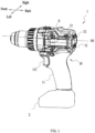
- FIG. 1 shows an electric tool as a specific example of the present disclosure.
- the electric tool is an electric drill 1, which can at least provide a torque to assist a screw to drive into a workpiece, and can provide an impact force for a hammering operation to meet the different needs of users.
- the following examples are some of the examples of the present disclosure, but not all of the examples of the present disclosure.
- the electric drill 1 includes a housing 10, a motor 20, a fan 30, a gearbox 40, an output shaft 50 and a drill bit (not shown in the drawings).
- the housing 10 is formed with a handle 11 for the users to hold.
- One end of the handle 11 is connected with a power interface for connecting to a DC or an AC power supply.
- a battery pack 2 is connected to the power interface, and the battery pack 2 is detachably connected to the electric drill 1.
- the power interface can also be connected to an alternating current, such as a commercial power.
- the handle 11 is also provided with a main control switch 111 for controlling the start and stop of the electric drill 1.
- the main control switch 111 can also realize a speed regulation function.
- the users control a rotation speed of the electric drill 1 by controlling a stroke of the main control switch 111 pressed.
- the housing 10 forms an accommodating space (not shown in the figure) along the direction of a first straight line 101, and the motor 20, the fan 30 and the gearbox 40 are sequentially arranged in the above accommodating space.
- the motor 20 is supported by the housing 10 and drives the output shaft 50 to drive the drill bit to rotate.
- the motor 20 includes a motor shaft 21, and the fan 30 is supported by the motor shaft 21 to dissipate heat for the electric drill 1.
- the electric drill 1 includes a transmission assembly 60, the gearbox 40 forms an accommodating space 41a, and the transmission assembly 60 is arranged in the accommodating space 41a.
- the transmission assembly 60 is connected to the motor shaft 21 and the output shaft 50.
- the motor 20 drives the output shaft 50 to rotate by means of the transmission assembly 60, thereby driving the drill bit to rotate to complete the processing of the workpiece.
- the users will encounter various working conditions when using the electric drill 1.
- the electric drill 1 in this example is a hand-held electric drill.
- the material of the gearbox 40 is plastic or other light materials, thereby reducing the weight of the electric drill 1.
- the high-speed operation of the motor 20 will inevitably cause the gearbox 40 to generate high heat. If the gearbox 40 is in a high-heat environment for a long time, a life of the gearbox 40 will inevitably be affected.
- an electric drill 1 will be introduced in detail, so that during the operation of the electric drill 1, especially during a high-speed operation of the electric drill 1, the heat of both the motor 20 and the gearbox 40 can be comprehensively and effectively dissipated, so that the electric drill 1 is structurally miniaturized and lightweight, while having good dissipation effect.
- the housing 10 is provided with a first air inlet 12 and a first air outlet 13.
- the first air inlet 12 is optionally provided on a rear side of the housing 10.
- the first air inlet 12 is also optionally provided on one of the left or right sides of the housing 10. It is to be understood that the first air inlet 12 should be provided on the housing 10 near the motor 20. In this disclosure, the number and specific positions of the first air inlet 12 are not limited, and the designer can design the first air inlet 12 based on actual usage.
- the first air outlet 13 is distributed on the housing 10 along the radial direction of the fan 30. Referring to FIG. 2 , in an example, the fan 30 is a double-blade fan.
- the fan 30 includes a first fan blade 31 close to the motor 20 and a second fan blade 32 close to the gearbox 40.
- the first air outlet 13 is arranged on the housing 10 along the radial direction of the first fan blade 31.
- the gearbox 40 includes a box body 41 and a gearbox rear cover 42.
- the box body 41 is formed with an accommodating space 41a for accommodating the transmission assembly 60.
- the box body 41 is made of a plastic material, which can reduce a weight of a complete machine of the electric drill 1.
- the gearbox rear cover 42 is arranged to be adjacent to the fan 30 along the direction of the first straight line 101.
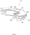
- the gearbox rear cover 42 is formed with a front surface 42a away from the fan 30, a rear surface 42b close to the fan 30, and an outer surface 42c.
- the gearbox rear cover 42 is made of metal or other materials with good thermal conductivity.
- the rear surface 42b of the gearbox rear cover 42 is provided opposite to the second fan blade 32 of the fan 30.
- the gearbox 40 includes a connecting portion 43 for a fixed connection between the box body 41 and the gearbox rear cover 42 during assembly.
- the box body 41 is provided with a slot 411
- the gearbox rear cover 42 is provided with a buckle 425 matching the slot 411.
- the fixed connection between the box body 41 and the gearbox rear cover 42 during assembly is realized by means of the slot 411 and the buckle 425.
- the gearbox 40 is provided with a passage 423 for the airflow to flow.
- the gearbox rear cover 42 since the gearbox rear cover 42 is provided with a passage 423 for the airflow to flow, the gearbox rear cover 42 must have a certain thickness, but the thickness of the gearbox rear cover 42 in this disclosure is not limited, and people who are skilled in the art can independently design the thickness of the gearbox rear cover 42 according to an actual situation.
- the gearbox rear cover 42 can be hollowed with a thickness, or the gearbox rear cover 42 can be solid with a thickness.
- the gearbox rear cover 42 is provided with a first vent 421 and a second vent 422.
- the first vent 421 and the second vent 422 constitute two ends of the passage 423.
- the first vent 421 is arranged along the circumferential direction of the gearbox rear cover 42, and the second vent 422 is provided on a surface of the gearbox 40 opposite to the fan 30.
- the housing 10 is also provided with a second air inlet 14 and a second air outlet 15. Specifically, the second air inlet 14 is arranged opposite to the first vent 421, and the second air outlet 15 is arranged along the radial direction of the second fan blade 32 of the fan 30.
- the fan 30 When the electric drill 1 is started, the fan 30 operates, the airflow enters the housing 10 from the second air inlet 14, enters the gearbox rear cover 42 from the first vent 421, flows through the passage 423, then flows out of the gearbox rear cover 42 from the second vent 422, and then flows out of the housing 10 from the second air outlet 15 after passing by the second fan blade 32. Most of the airflow in the above heat dissipation process of the gearbox 40 is generated by the second fan blade 32.
- both the first air outlet 13 and the second air outlet 15 are provided on the housing 10 along the radial direction of the fan 30.
- the first air outlet 13 is arranged on the housing 10 along the radial direction of the first fan blade 31.
- the second air outlet 15 is arranged on the housing 10 along the radial direction of the second fan blade 32 of the fan 30.
- the first air outlet 13 and the second air outlet 15 are relatively close but isolated from each other, so that most of the airflow entering from the first air inlet 12 flows out of the first air outlet 13, and most of the airflow entering from the air outlet 14 flows out of the second air outlet 15. According to this design, a flow rate of the airflow can be maximized, and a heat dissipation effect of the electric drill 1 can be improved.
- the passage 423 includes a first portion 423a and a second portion 423b.
- the first portion 423a is provided between a front surface 42a and a rear surface 42b of the gearbox rear cover 42.
- the second portion 423b is disposed between an outer surface 42c and an inner surface 42d of the gearbox rear cover 42.
- the first vent 421 is provided on the first portion 423a and is distributed on the outer surface 42c of the gearbox rear cover 42 in the circumferential direction of the gearbox rear cover 42.
- the connecting portion 43 as a central axis, the first vent 421 is symmetrically distributed on both sides of the connecting portion 43.
- the second vent 422 is disposed on the second portion 423b of the passage 423, and is symmetrically distributed on the rear surface 42b of the gearbox rear cover 42 with the connecting portion 43 as the central axis.
- the first vent 421 is set as an entrance of the airflow
- the second vent 422 is set as an exit of the airflow.
- the gearbox rear cover 42 also includes a diverter rib 424 for an airflow guidance.
- a plurality of diverter ribs 424 are set in the passage 423.
- the diverter rib 424 is provided in the first portion 423a of the passage 423.
- the diverter rib 424 is provided between the front surface 42a and the rear surface 42b of the gearbox rear cover 42, and divides the first portion 423a of the passage 423 into several fan-shaped portions.
- the airflow flows to the first vent 421, the airflow is divided into multiple airflows by a plurality of diverter ribs 424. As shown by arrow a in FIG.
- a total area of the first vent 421 in this example is set to be greater than or equal to a total area of the second vent 422.
- the total area of the first vent 421 and the total area of the second vent 422 are not limited, and the designer can design the first vent 421 and the second vent 422 according to a specific operating environment.
Landscapes
- Engineering & Computer Science (AREA)
- Mechanical Engineering (AREA)
- Power Engineering (AREA)
- Cooling Or The Like Of Electrical Apparatus (AREA)
Claims (12)
- Une perceuse électrique (1), comprenant :un boîtier (10) comportant une entrée d'air et une sortie d'air ;un moteur (20) logé dans le boîtier (10), le moteur (20) comprenant au moins un arbre de moteur (21) ;un ventilateur (30) supporté par l'arbre de moteur (21) ;un ensemble de transmission (60) configuré pour connecter l'arbre de moteur (21) à un arbre de sortie (50) ; etun boîtier d'engrenage (40) configuré pour loger l'ensemble de transmission (60), le boîtier d'engrenage (40) comprenant un corps de boîtier (41) et un couvercle arrière de boîtier d'engrenage (42), le couvercle arrière de boîtier d'engrenage (42) étant disposé en face du ventilateur (30) selon la direction d'extension de l'arbre de moteur (21), caractérisée en ce quele boîtier d'engrenage (40) est formé d'un passage (423) disposé dans le couvercle arrière de boîtier d'engrenage (42) et permettant un écoulement d'air, et au moins une partie du trajet d'écoulement de l'air entrant dans le boîtier (10) par l'entrée d'air et sortant du boîtier (10) par la sortie d'air est disposée dans le passage (423).
- La perceuse électrique (1) selon la revendication 1, dans laquelle une nervure de dérivation (424) configurée pour guider le flux d'air est disposée à l'intérieur du passage (423).
- La perceuse électrique (1) selon la revendication 1, dans laquelle une surface externe du boîtier d'engrenage (40) s'étendant dans une direction circonférentielle est pourvue d'une première ouverture de ventilation (421), la première ouverture de ventilation (421) étant disposée à une extrémité du passage (423), une surface arrière du boîtier d'engrenage (40) opposée au ventilateur (30) étant pourvue d'une deuxième ouverture de ventilation (422), et la deuxième ouverture de ventilation (422) étant disposée à l'autre extrémité du passage (423).
- La perceuse électrique (1) selon la revendication 1, dans laquelle le boîtier (10) est pourvu d'une première entrée d'air (12) configurée pour refroidir le moteur (20).
- La perceuse électrique (1) selon la revendication 3, dans laquelle le boîtier (10) est pourvu d'une deuxième entrée d'air (14) située en face de la première ouverture de ventilation (421).
- La perceuse électrique (1) selon la revendication 1, dans laquelle une première pale de ventilateur (31) est disposée sur un côté du ventilateur (30) opposé au moteur (20), et une deuxième pale de ventilateur (32) est disposée sur un côté du ventilateur (30) opposé au boîtier d'engrenage (40).
- La perceuse électrique (1) selon la revendication 6, dans laquelle le boîtier (10) est pourvu d'une première sortie d'air (13), et la première sortie d'air (13) est disposée selon la direction radiale de la première pale de ventilateur (31).
- La perceuse électrique (1) selon la revendication 6, dans laquelle le boîtier (10) est pourvu d'une deuxième sortie d'air (15), et la deuxième sortie d'air (15) est disposée selon la direction radiale de la deuxième pale de ventilateur (32).
- La perceuse électrique (1) selon la revendication 1, dans laquelle une surface externe (42c) du couvercle arrière de boîtier d'engrenage (42) s'étendant dans une direction circonférentielle est pourvue d'une première ouverture de ventilation (421), la première ouverture de ventilation (421) étant disposée à une extrémité du passage (423), une surface arrière (42b) du couvercle arrière de boîtier d'engrenage (42) opposée au ventilateur (30) étant pourvue d'une deuxième ouverture de ventilation (422), et la deuxième ouverture de ventilation (422) étant disposée à l'autre extrémité du passage (423).
- La perceuse électrique (1) selon la revendication 1, dans laquelle le couvercle arrière de boîtier d'engrenage (42) est fabriqué en matériau métallique.
- La perceuse électrique (1) selon la revendication 1, dans laquelle une nervure de dérivation (424) configurée pour guider le flux d'air est disposée à l'intérieur du passage (423).
- La perceuse électrique (1) selon la revendication 1, dans laquelle une surface externe du boîtier d'engrenage (40) s'étendant dans une direction circonférentielle est pourvue d'une première ouverture de ventilation (421), la première ouverture de ventilation (421) étant disposée à une extrémité du passage (423), une surface arrière du boîtier d'engrenage (40) opposée au ventilateur (30) étant pourvue d'une deuxième ouverture de ventilation (422), et la deuxième ouverture de ventilation (422) étant disposée à l'autre extrémité du passage (423).
Applications Claiming Priority (1)
| Application Number | Priority Date | Filing Date | Title |
|---|---|---|---|
| CN202110760646.XA CN115570179A (zh) | 2021-07-06 | 2021-07-06 | 电钻及电动工具 |
Publications (2)
| Publication Number | Publication Date |
|---|---|
| EP4122647A1 EP4122647A1 (fr) | 2023-01-25 |
| EP4122647B1 true EP4122647B1 (fr) | 2025-04-23 |
Family
ID=82547399
Family Applications (1)
| Application Number | Title | Priority Date | Filing Date |
|---|---|---|---|
| EP22180281.2A Active EP4122647B1 (fr) | 2021-07-06 | 2022-06-22 | Foret électrique et outil électrique |
Country Status (3)
| Country | Link |
|---|---|
| US (1) | US12365077B2 (fr) |
| EP (1) | EP4122647B1 (fr) |
| CN (1) | CN115570179A (fr) |
Families Citing this family (1)
| Publication number | Priority date | Publication date | Assignee | Title |
|---|---|---|---|---|
| CN117340827A (zh) * | 2023-11-21 | 2024-01-05 | 浙江贝托传动科技有限公司 | 一种小型扭矩增力扳手 |
Family Cites Families (31)
| Publication number | Priority date | Publication date | Assignee | Title |
|---|---|---|---|---|
| US3302047A (en) * | 1964-12-24 | 1967-01-31 | Black & Decker Mfg Co | Fan assembly for high-torque application |
| US3652879A (en) * | 1970-07-22 | 1972-03-28 | Thor Power Tool Co | Electric power tool |
| DE2257509C2 (de) * | 1972-11-23 | 1982-09-02 | Papst-Motoren GmbH & Co KG, 7742 St Georgen | Radialgebläse |
| US3829721A (en) * | 1973-07-30 | 1974-08-13 | Black & Decker Mfg Co | Air flow baffle construction for electric motor devices |
| DE4003029A1 (de) * | 1990-02-02 | 1991-08-08 | Bosch Gmbh Robert | Handgefuehrte werkzeugmaschine mit radialgeblaese |
| GB9123502D0 (en) * | 1991-11-06 | 1992-01-02 | Black & Decker Inc | Sanding apparatus |
| US5580302A (en) * | 1994-02-28 | 1996-12-03 | Black & Decker Inc. | Random orbit sander having air directing baffle |
| US5632578A (en) * | 1996-02-23 | 1997-05-27 | Ryobi North America | Exhaust stator and fan for a power tool |
| DE19924552A1 (de) * | 1999-05-28 | 2000-11-30 | Hilti Ag | Elektrisch betreibbares Handgerät |
| US6703754B1 (en) * | 2001-10-01 | 2004-03-09 | Ametek, Inc. | Electric motor and brush retaining assembly |
| JP4075540B2 (ja) * | 2002-09-10 | 2008-04-16 | 松下電工株式会社 | 電動工具 |
| DE10242738A1 (de) * | 2002-09-13 | 2005-01-20 | Robert Bosch Gmbh | Handwekzeugmaschine, insbesondere Winkelschleifmaschine |
| DE10261572A1 (de) | 2002-12-23 | 2004-07-01 | Robert Bosch Gmbh | Elektrohandwerkzeugmaschine |
| CA2655134C (fr) * | 2006-06-07 | 2017-07-04 | A.O. Smith Corporation | Moteur refroidi par ventilateur totalement confine |
| DE102006029626A1 (de) * | 2006-06-28 | 2008-01-03 | Robert Bosch Gmbh | Elektrohandwerkzeugmaschine mit Saugmodul für eine Staubabscheidevorrichtung |
| US7988538B2 (en) * | 2006-10-13 | 2011-08-02 | Black & Decker Inc. | Large angle grinder |
| DE102008059599A1 (de) * | 2008-11-28 | 2010-06-02 | Aeg Electric Tools Gmbh | Elektrowerkzeug |
| DE102010031274B4 (de) * | 2009-12-18 | 2023-06-22 | Robert Bosch Gmbh | Handwerkzeugmaschine mit Kühlung des Getriebes |
| EP2337186B1 (fr) * | 2009-12-18 | 2016-09-21 | Ziehl-Abegg Se | Moteur électrique à rotor externe |
| DE112012003045B4 (de) * | 2011-07-07 | 2024-01-04 | Makita Corporation | Kraftwerkzeug |
| JP6127840B2 (ja) * | 2013-09-02 | 2017-05-17 | 日立工機株式会社 | 電動工具 |
| GB201413008D0 (en) * | 2014-07-23 | 2014-09-03 | Black & Decker Inc | A range of power tools |
| US9505119B2 (en) * | 2015-02-19 | 2016-11-29 | X'pole Precision Tools Inc. | Electric handheld sanding tool providing improved cooling efficiency |
| JP2017094453A (ja) * | 2015-11-25 | 2017-06-01 | パナソニックIpマネジメント株式会社 | 電動工具 |
| DE102016015535A1 (de) * | 2016-12-19 | 2018-06-21 | Ziehl-Abegg Se | Kühlvorrichtung eines Elektromotors sowie Elektromotor mit Kühlvorrichtung |
| WO2018180083A1 (fr) * | 2017-03-30 | 2018-10-04 | 工機ホールディングス株式会社 | Outil rotatif |
| CN108789283B (zh) * | 2017-05-05 | 2021-11-19 | 南京德朔实业有限公司 | 扭力输出工具 |
| CN107081447A (zh) * | 2017-06-21 | 2017-08-22 | 宁波恒进自动化技术有限公司 | 一种带吹风功能的多钻头电钻 |
| DE202018104460U1 (de) * | 2017-09-29 | 2018-08-16 | Nanjing Chervon Industry Co., Ltd. | Elektrohandwerkzeug |
| CN107999827A (zh) * | 2017-12-27 | 2018-05-08 | 宁波奥高科技有限公司 | 一种电动工具 |
| US11139722B2 (en) * | 2018-03-02 | 2021-10-05 | Black & Decker Inc. | Motor having an external heat sink for a power tool |
-
2021
- 2021-07-06 CN CN202110760646.XA patent/CN115570179A/zh active Pending
-
2022
- 2022-06-22 EP EP22180281.2A patent/EP4122647B1/fr active Active
- 2022-06-22 US US17/846,665 patent/US12365077B2/en active Active
Also Published As
| Publication number | Publication date |
|---|---|
| US12365077B2 (en) | 2025-07-22 |
| CN115570179A (zh) | 2023-01-06 |
| US20230007837A1 (en) | 2023-01-12 |
| EP4122647A1 (fr) | 2023-01-25 |
Similar Documents
| Publication | Publication Date | Title |
|---|---|---|
| EP1398864B1 (fr) | Outil électrique | |
| EP1715565B1 (fr) | Outil motorisé | |
| CN102256753B (zh) | 作业工具 | |
| US12092130B2 (en) | Blower | |
| EP1621293B1 (fr) | Machine-outil | |
| CN111376351A (zh) | 链锯 | |
| US10836027B2 (en) | Hand-held electric power tool | |
| EP4122647B1 (fr) | Foret électrique et outil électrique | |
| CN215392873U (zh) | 交流无刷切割工具 | |
| WO2019096223A1 (fr) | Moteur applicable à un outil électrique portatif, et outil électrique portatif | |
| JP7316353B2 (ja) | 動力工具 | |
| JP4485190B2 (ja) | 電動ハンマ | |
| CN112077799B (zh) | 一种电动工具 | |
| US20120152504A1 (en) | Handheld power tool with air-guiding element | |
| CN218658894U (zh) | 电动工具 | |
| EP4368339B1 (fr) | Machine de meulage d'outil électrique et couvercle de disque de meulage | |
| CN117620307A (zh) | 手持式带锯 | |
| US20260039171A1 (en) | Power tool and electric motor | |
| CN220874838U (zh) | 控制器及电动工具 | |
| JP7780112B2 (ja) | 作業機 | |
| CN210819415U (zh) | 锤击工具 | |
| CN115805615A (zh) | 手持式电圆锯 | |
| CN117505988A (zh) | 电动工具 | |
| CN115805613A (zh) | 手持式电圆锯 | |
| CN115805614A (zh) | 手持式电圆锯 |
Legal Events
| Date | Code | Title | Description |
|---|---|---|---|
| PUAI | Public reference made under article 153(3) epc to a published international application that has entered the european phase |
Free format text: ORIGINAL CODE: 0009012 |
|
| STAA | Information on the status of an ep patent application or granted ep patent |
Free format text: STATUS: THE APPLICATION HAS BEEN PUBLISHED |
|
| AK | Designated contracting states |
Kind code of ref document: A1 Designated state(s): AL AT BE BG CH CY CZ DE DK EE ES FI FR GB GR HR HU IE IS IT LI LT LU LV MC MK MT NL NO PL PT RO RS SE SI SK SM TR |
|
| STAA | Information on the status of an ep patent application or granted ep patent |
Free format text: STATUS: REQUEST FOR EXAMINATION WAS MADE |
|
| 17P | Request for examination filed |
Effective date: 20230704 |
|
| RBV | Designated contracting states (corrected) |
Designated state(s): AL AT BE BG CH CY CZ DE DK EE ES FI FR GB GR HR HU IE IS IT LI LT LU LV MC MK MT NL NO PL PT RO RS SE SI SK SM TR |
|
| RIC1 | Information provided on ipc code assigned before grant |
Ipc: B25F 5/00 20060101ALI20231221BHEP Ipc: B25F 1/00 20060101AFI20231221BHEP |
|
| STAA | Information on the status of an ep patent application or granted ep patent |
Free format text: STATUS: EXAMINATION IS IN PROGRESS |
|
| 17Q | First examination report despatched |
Effective date: 20240823 |
|
| GRAP | Despatch of communication of intention to grant a patent |
Free format text: ORIGINAL CODE: EPIDOSNIGR1 |
|
| STAA | Information on the status of an ep patent application or granted ep patent |
Free format text: STATUS: GRANT OF PATENT IS INTENDED |
|
| GRAS | Grant fee paid |
Free format text: ORIGINAL CODE: EPIDOSNIGR3 |
|
| GRAA | (expected) grant |
Free format text: ORIGINAL CODE: 0009210 |
|
| STAA | Information on the status of an ep patent application or granted ep patent |
Free format text: STATUS: THE PATENT HAS BEEN GRANTED |
|
| INTG | Intention to grant announced |
Effective date: 20250219 |
|
| AK | Designated contracting states |
Kind code of ref document: B1 Designated state(s): AL AT BE BG CH CY CZ DE DK EE ES FI FR GB GR HR HU IE IS IT LI LT LU LV MC MK MT NL NO PL PT RO RS SE SI SK SM TR |
|
| REG | Reference to a national code |
Ref country code: GB Ref legal event code: FG4D |
|
| REG | Reference to a national code |
Ref country code: CH Ref legal event code: EP |
|
| REG | Reference to a national code |
Ref country code: DE Ref legal event code: R096 Ref document number: 602022013421 Country of ref document: DE |
|
| REG | Reference to a national code |
Ref country code: IE Ref legal event code: FG4D |
|
| PGFP | Annual fee paid to national office [announced via postgrant information from national office to epo] |
Ref country code: DE Payment date: 20250429 Year of fee payment: 4 |
|
| PGFP | Annual fee paid to national office [announced via postgrant information from national office to epo] |
Ref country code: FR Payment date: 20250508 Year of fee payment: 4 |
|
| PGFP | Annual fee paid to national office [announced via postgrant information from national office to epo] |
Ref country code: AT Payment date: 20250721 Year of fee payment: 4 |
|
| REG | Reference to a national code |
Ref country code: NL Ref legal event code: MP Effective date: 20250423 |
|
| PG25 | Lapsed in a contracting state [announced via postgrant information from national office to epo] |
Ref country code: NL Free format text: LAPSE BECAUSE OF FAILURE TO SUBMIT A TRANSLATION OF THE DESCRIPTION OR TO PAY THE FEE WITHIN THE PRESCRIBED TIME-LIMIT Effective date: 20250423 |
|
| REG | Reference to a national code |
Ref country code: AT Ref legal event code: MK05 Ref document number: 1787346 Country of ref document: AT Kind code of ref document: T Effective date: 20250423 |
|
| PG25 | Lapsed in a contracting state [announced via postgrant information from national office to epo] |
Ref country code: FI Free format text: LAPSE BECAUSE OF FAILURE TO SUBMIT A TRANSLATION OF THE DESCRIPTION OR TO PAY THE FEE WITHIN THE PRESCRIBED TIME-LIMIT Effective date: 20250423 Ref country code: ES Free format text: LAPSE BECAUSE OF FAILURE TO SUBMIT A TRANSLATION OF THE DESCRIPTION OR TO PAY THE FEE WITHIN THE PRESCRIBED TIME-LIMIT Effective date: 20250423 Ref country code: PT Free format text: LAPSE BECAUSE OF FAILURE TO SUBMIT A TRANSLATION OF THE DESCRIPTION OR TO PAY THE FEE WITHIN THE PRESCRIBED TIME-LIMIT Effective date: 20250825 |
|
| REG | Reference to a national code |
Ref country code: LT Ref legal event code: MG9D |
|
| PG25 | Lapsed in a contracting state [announced via postgrant information from national office to epo] |
Ref country code: NO Free format text: LAPSE BECAUSE OF FAILURE TO SUBMIT A TRANSLATION OF THE DESCRIPTION OR TO PAY THE FEE WITHIN THE PRESCRIBED TIME-LIMIT Effective date: 20250723 Ref country code: GR Free format text: LAPSE BECAUSE OF FAILURE TO SUBMIT A TRANSLATION OF THE DESCRIPTION OR TO PAY THE FEE WITHIN THE PRESCRIBED TIME-LIMIT Effective date: 20250724 |
|
| PG25 | Lapsed in a contracting state [announced via postgrant information from national office to epo] |
Ref country code: PL Free format text: LAPSE BECAUSE OF FAILURE TO SUBMIT A TRANSLATION OF THE DESCRIPTION OR TO PAY THE FEE WITHIN THE PRESCRIBED TIME-LIMIT Effective date: 20250423 |
|
| PG25 | Lapsed in a contracting state [announced via postgrant information from national office to epo] |
Ref country code: BG Free format text: LAPSE BECAUSE OF FAILURE TO SUBMIT A TRANSLATION OF THE DESCRIPTION OR TO PAY THE FEE WITHIN THE PRESCRIBED TIME-LIMIT Effective date: 20250423 |
|
| PG25 | Lapsed in a contracting state [announced via postgrant information from national office to epo] |
Ref country code: HR Free format text: LAPSE BECAUSE OF FAILURE TO SUBMIT A TRANSLATION OF THE DESCRIPTION OR TO PAY THE FEE WITHIN THE PRESCRIBED TIME-LIMIT Effective date: 20250423 Ref country code: AT Free format text: LAPSE BECAUSE OF FAILURE TO SUBMIT A TRANSLATION OF THE DESCRIPTION OR TO PAY THE FEE WITHIN THE PRESCRIBED TIME-LIMIT Effective date: 20250423 |
|
| PG25 | Lapsed in a contracting state [announced via postgrant information from national office to epo] |
Ref country code: RS Free format text: LAPSE BECAUSE OF FAILURE TO SUBMIT A TRANSLATION OF THE DESCRIPTION OR TO PAY THE FEE WITHIN THE PRESCRIBED TIME-LIMIT Effective date: 20250723 |
|
| PG25 | Lapsed in a contracting state [announced via postgrant information from national office to epo] |
Ref country code: IS Free format text: LAPSE BECAUSE OF FAILURE TO SUBMIT A TRANSLATION OF THE DESCRIPTION OR TO PAY THE FEE WITHIN THE PRESCRIBED TIME-LIMIT Effective date: 20250823 |
|
| PG25 | Lapsed in a contracting state [announced via postgrant information from national office to epo] |
Ref country code: LV Free format text: LAPSE BECAUSE OF FAILURE TO SUBMIT A TRANSLATION OF THE DESCRIPTION OR TO PAY THE FEE WITHIN THE PRESCRIBED TIME-LIMIT Effective date: 20250423 |
|
| PG25 | Lapsed in a contracting state [announced via postgrant information from national office to epo] |
Ref country code: DK Free format text: LAPSE BECAUSE OF FAILURE TO SUBMIT A TRANSLATION OF THE DESCRIPTION OR TO PAY THE FEE WITHIN THE PRESCRIBED TIME-LIMIT Effective date: 20250423 Ref country code: SM Free format text: LAPSE BECAUSE OF FAILURE TO SUBMIT A TRANSLATION OF THE DESCRIPTION OR TO PAY THE FEE WITHIN THE PRESCRIBED TIME-LIMIT Effective date: 20250423 |
|
| PG25 | Lapsed in a contracting state [announced via postgrant information from national office to epo] |
Ref country code: CZ Free format text: LAPSE BECAUSE OF FAILURE TO SUBMIT A TRANSLATION OF THE DESCRIPTION OR TO PAY THE FEE WITHIN THE PRESCRIBED TIME-LIMIT Effective date: 20250423 |
|
| PG25 | Lapsed in a contracting state [announced via postgrant information from national office to epo] |
Ref country code: EE Free format text: LAPSE BECAUSE OF FAILURE TO SUBMIT A TRANSLATION OF THE DESCRIPTION OR TO PAY THE FEE WITHIN THE PRESCRIBED TIME-LIMIT Effective date: 20250423 |
|
| REG | Reference to a national code |
Ref country code: DE Ref legal event code: R097 Ref document number: 602022013421 Country of ref document: DE |
|
| PG25 | Lapsed in a contracting state [announced via postgrant information from national office to epo] |
Ref country code: SK Free format text: LAPSE BECAUSE OF FAILURE TO SUBMIT A TRANSLATION OF THE DESCRIPTION OR TO PAY THE FEE WITHIN THE PRESCRIBED TIME-LIMIT Effective date: 20250423 |
|
| REG | Reference to a national code |
Ref country code: CH Ref legal event code: H13 Free format text: ST27 STATUS EVENT CODE: U-0-0-H10-H13 (AS PROVIDED BY THE NATIONAL OFFICE) Effective date: 20260127 |
|
| PG25 | Lapsed in a contracting state [announced via postgrant information from national office to epo] |
Ref country code: IT Free format text: LAPSE BECAUSE OF FAILURE TO SUBMIT A TRANSLATION OF THE DESCRIPTION OR TO PAY THE FEE WITHIN THE PRESCRIBED TIME-LIMIT Effective date: 20250423 |
|
| PG25 | Lapsed in a contracting state [announced via postgrant information from national office to epo] |
Ref country code: MC Free format text: LAPSE BECAUSE OF FAILURE TO SUBMIT A TRANSLATION OF THE DESCRIPTION OR TO PAY THE FEE WITHIN THE PRESCRIBED TIME-LIMIT Effective date: 20250423 |
|
| PG25 | Lapsed in a contracting state [announced via postgrant information from national office to epo] |
Ref country code: RO Free format text: LAPSE BECAUSE OF FAILURE TO SUBMIT A TRANSLATION OF THE DESCRIPTION OR TO PAY THE FEE WITHIN THE PRESCRIBED TIME-LIMIT Effective date: 20250423 |
|
| PG25 | Lapsed in a contracting state [announced via postgrant information from national office to epo] |
Ref country code: LU Free format text: LAPSE BECAUSE OF NON-PAYMENT OF DUE FEES Effective date: 20250622 |
|
| REG | Reference to a national code |
Ref country code: BE Ref legal event code: MM Effective date: 20250630 |
|
| PLBE | No opposition filed within time limit |
Free format text: ORIGINAL CODE: 0009261 |
|
| STAA | Information on the status of an ep patent application or granted ep patent |
Free format text: STATUS: NO OPPOSITION FILED WITHIN TIME LIMIT |
|
| REG | Reference to a national code |
Ref country code: CH Ref legal event code: L10 Free format text: ST27 STATUS EVENT CODE: U-0-0-L10-L00 (AS PROVIDED BY THE NATIONAL OFFICE) Effective date: 20260304 |
|
| 26N | No opposition filed |
Effective date: 20260126 |
|
| PG25 | Lapsed in a contracting state [announced via postgrant information from national office to epo] |
Ref country code: IE Free format text: LAPSE BECAUSE OF NON-PAYMENT OF DUE FEES Effective date: 20250622 |
|
| PG25 | Lapsed in a contracting state [announced via postgrant information from national office to epo] |
Ref country code: BE Free format text: LAPSE BECAUSE OF NON-PAYMENT OF DUE FEES Effective date: 20250630 |
|
| PG25 | Lapsed in a contracting state [announced via postgrant information from national office to epo] |
Ref country code: CH Free format text: LAPSE BECAUSE OF NON-PAYMENT OF DUE FEES Effective date: 20250630 |