EP4122690A1 - Module de modernisation pour une presse à estamper, ainsi que procédé de montage et presse à estamper - Google Patents
Module de modernisation pour une presse à estamper, ainsi que procédé de montage et presse à estamper Download PDFInfo
- Publication number
- EP4122690A1 EP4122690A1 EP22176089.5A EP22176089A EP4122690A1 EP 4122690 A1 EP4122690 A1 EP 4122690A1 EP 22176089 A EP22176089 A EP 22176089A EP 4122690 A1 EP4122690 A1 EP 4122690A1
- Authority
- EP
- European Patent Office
- Prior art keywords
- offset
- ram
- machine housing
- columns
- retrofit assembly
- Prior art date
- Legal status (The legal status is an assumption and is not a legal conclusion. Google has not performed a legal analysis and makes no representation as to the accuracy of the status listed.)
- Granted
Links
Images


Classifications
-
- B—PERFORMING OPERATIONS; TRANSPORTING
- B30—PRESSES
- B30B—PRESSES IN GENERAL
- B30B15/00—Details of, or accessories for, presses; Auxiliary measures in connection with pressing
- B30B15/0029—Details of, or accessories for, presses; Auxiliary measures in connection with pressing means for adjusting the space between the press slide and the press table, i.e. the shut height
- B30B15/0035—Details of, or accessories for, presses; Auxiliary measures in connection with pressing means for adjusting the space between the press slide and the press table, i.e. the shut height using an adjustable connection between the press drive means and the press slide
-
- B—PERFORMING OPERATIONS; TRANSPORTING
- B30—PRESSES
- B30B—PRESSES IN GENERAL
- B30B15/00—Details of, or accessories for, presses; Auxiliary measures in connection with pressing
- B30B15/0088—Lubricating means
-
- B—PERFORMING OPERATIONS; TRANSPORTING
- B30—PRESSES
- B30B—PRESSES IN GENERAL
- B30B15/00—Details of, or accessories for, presses; Auxiliary measures in connection with pressing
- B30B15/04—Frames; Guides
- B30B15/041—Guides
-
- B—PERFORMING OPERATIONS; TRANSPORTING
- B30—PRESSES
- B30B—PRESSES IN GENERAL
- B30B15/00—Details of, or accessories for, presses; Auxiliary measures in connection with pressing
- B30B15/06—Platens or press rams
Definitions
- the present invention relates to a retrofit assembly for a stamping press according to the preamble of claim 1, a method for assembling the retrofit assembly, and a stamping press with an installed retrofit assembly.
- stamping presses or also called stamping machines are used to produce stamped parts, in particular with progressive dies.
- more complex tools are used, which in particular include several punching stages.
- the tools in a tool plane are dimensioned larger and also require a larger installation space with a correspondingly widened ram to accommodate the tool.
- the installation space would have to be expanded to accommodate the larger tool using a retrofit solution.
- Such a retrofit solution to expand the installation space of older stamping presses is in DE 10 2008 053 561 B4 discloses a stamping press having an upper machine housing, a ram with pressure columns and an underlying mounting space, the mounting space being limited between the ram, lateral guide columns and a base plate opposite the ram.
- the guide columns are offset laterally by a width offset relative to the machine housing by means of lateral wedges as retrofit components. These wedges being arranged laterally on the machine body and supported on the guide columns.
- the present invention is based on the object of proposing a retrofit assembly for a stamping press which, while avoiding the problems known from the prior art, provides a particularly inexpensive and/or inexpensive to produce retrofit assembly which, in the assembled state, is subject to a force curve and/or loads within the Stamping press is/are adapted.
- the object consists in specifying a method for assembling the retrofit assembly, as well as a stamping press with a machine housing, guide columns and the retrofit assembly according to the invention.
- a retrofit assembly for a stamping press is claimed, the stamping press forming an installation space with a ram, lateral guide columns of the ram and an opposite base plate, the retrofit assembly having spacer means in order to expand the installation space at least by a width offset in a width direction, and the retrofit assembly Has pressure columns for receiving a widened ram, which are stored in the assembled state in a machine housing of the punch press.
- the spacer means can be mounted in a height direction between the machine housing and the guide columns offset in the width direction and the retrofittable pressure columns for receiving the ram are lengthened along the height direction, in particular by a height offset by the spacer means.
- the spacers in particular as spacer blocks or transition pieces, are arranged for load transfer between the machine housing and the laterally offset guide columns, with the machine housing also being offset in the vertical direction relative to the guide columns by the spacer means and next to the lateral expanded installation space below the ram and a mounting space below the machine housing is also increased. Due to the offset in the height direction, the pressure columns are also lengthened in order to State record a widened ram, which preferably just needs this increased mounting space for assembly.
- the spacer means can dissipate a weight and loads during a stamping process as effectively and force-optimized as possible from the machine housing into the guide columns, with existing connection points or bearing surfaces of the machine housing being used, which were already designed according to the loads .
- a course of force is thus diverted between the connection points, which are mechanically adapted to the prevailing loads, without interruption by the spacer means.
- no additional connection points, such as bores or threaded bores are advantageously necessary, in particular in one side of the machine housing, and existing fastening points and/or functional connection points, such as connections for fluid channels, can advantageously continue to be used.
- the spacer means are designed in such a way that their contact surfaces extend over the entire bearing surfaces of the machine housing and the guide columns in the assembled state.
- the retrofittable pressure columns have a connecting section that is lengthened at the end and offset laterally with respect to a longitudinal extension axis of the pressure columns, which is designed to accommodate a widened ram with receiving openings that are spaced apart at a widened side.
- the pressure columns can be inserted into existing receptacles in the machine housing, and a ram with receptacle openings that are spaced apart more widely can also be connected to the pressure columns through the connecting section and a broadening at the end.
- a widened ram with receiving openings that have a wider spacing, improved force application points for an optimized transmission of forces between the pressure columns and the widened ram.
- the pressure columns can counteract tilting of the ram in an advantageously improved manner due to the receiving openings, which are spaced more widely apart from one another.
- a ram which is provided in particular as a standard component for a larger and/or newer punching machine, can also advantageously be used in older punching machines and/or punching machines with originally smaller installation space thanks to the retrofit assembly.
- a standard component from the Bruderer company can be used for newer and/or larger punching machines, with a new force-optimized development of a design and/or manufacturing process for the ram, in particular no cost-intensive special production, advantageously not being necessary.
- parts can advantageously be obtained from a spare parts inventory for newer and/or larger punching machines and/or reused in smaller ones from larger punching machines that have already been converted. In this way, downward compatibility from newer and/or larger to older and/or smaller punching machines is made possible.
- a BSTA 50 L machine can be expanded with parts from a BSTA 50 SL machine, with parts then being available at the same time, in order to convert the installation space of a BSTA 50 machine into a BSTA type stamping machine 50 L to retrofit.
- An example of a BSTA 500-110B combination is a Bruderer automatic punching machine that has a punching force of 500kN, an installation space length of 1100mm and a B control.
- the connecting section can preferably also be designed as a straight spacer in a vertical direction in order to lengthen the pressure columns.
- the pressure columns can then preferably be offset laterally outwards within the machine housing.
- the widened ram can also be driven at the points of the original ram, with the widened ram having the same receiving openings, preferably for force optimization, having a widened receiving geometry and/or being widened in the height direction.
- the height offset due to the spacer means and an enlarged assembly space below the machine housing is also advantageous in these embodiments.
- the retrofittable pressure columns are particularly preferably designed in two parts with an upper part, which comprises a first receptacle for connection to a lifting device inside the machine housing, and a lower part as the connection section described above, with the upper part having an L-shaped recess at the end, into which the lower part with a second receptacle offset by the lateral offset with respect to the axis of longitudinal extent of the pressure column, here the upper part, engages in a form-fitting manner, the two parts of the pressure columns preferably being fixable to one another by means of a screw connection.
- the retrofittable pressure columns can preferably be produced from existing pressure columns by post-processing, with the L-shaped recess being made in a post-processing step, preferably by machining, in particular milling, in order to be able to turn at least the upper part of an existing pressure column again.
- the form-fitting contact of the connecting section within the L-shaped recess in the assembled state enables the largest possible overlap with the cross section of the upper part of the pressure column and optimal force transmission along the longitudinal axis of the pressure column.
- the retrofittable pressure column can also be produced in one piece with a connecting section at the end, in particular in a metal casting process.
- the retrofittable pressure columns and the connecting section particularly preferably have fluid channels, in particular for lubricants, in order to directing a fluid from the machine housing into a bearing point of the rams.
- a fluid supply and a fluid return channel are preferably arranged within the pressure columns and the connecting section in order to enable fluid circulation.
- the fluid channels are preferably arranged within the connecting section in accordance with the already existing and post-processed pressure columns.
- the spacer means laterally displace the guide columns in the assembled state in such a way that a projection of a bearing surface of the machine housing in the height direction at least partially overlaps an opposite bearing surface of the guide columns, preferably with at least half the bearing surface in the width direction.
- the spacer means preferably also have fluid channels, in particular for lubricants, in order to conduct a fluid from the machine housing into the guide supports.
- the connections of the fluid channels are preferably adapted to the connections in the bearing surfaces in the machine housing and the guide columns.
- the retrofit assembly includes a ram widened in the width direction and/or a widened base plate and/or a clamping plate for a widened tool, these additional retrofit components, in particular the ram, representing standard components and the spacers and/or the pressure columns being adapted to the dimensions of the standard components.
- the invention also relates to a method for installing a retrofit assembly, preferably an already described retrofit assembly, in an existing stamping press, which forms an installation space with a ram, lateral guide columns of the ram and an opposite base plate.
- a preferred process sequence is given in the following process steps, but the invention is not intended to be limited to these.
- the installation space is expanded by offsetting the lateral guide columns at least by an offset in width on the base plate, in particular on a base plate that is also expanded laterally by the offset in width.
- the spacer means are mounted between the machine housing and the guide columns offset in the width direction, and the machine housing is raised by a height offset relative to the guide columns.
- retrofittable pressure columns are used in the machine housing of the stamping press, which are preferably lengthened in accordance with a height offset of the spacer means.
- the pressure columns are connected to a ram that is widened according to the width offset.
- the retrofittable pressure columns are particularly preferably mounted with an upper part with a first receptacle on a lifting device inside the machine housing and a connecting section is mounted on a lower part, which has a lateral offset with respect to the longitudinal axis of the pressure column, here the upper part.
- a tappet with laterally widened spacing of the receiving openings is preferably mounted on a laterally offset second receptacle of the connecting section.
- the retrofittable pressure columns are aligned and preferred at connection points, in particular fluid ducts and/or bores, of the machine housing and/or the ram, and the retrofittable spacers at connection points, in particular fluid ducts and/or bores, of the machine housing and/or the guide supports fixed in the aligned state.
- the invention relates to a stamping press with a machine housing, guide columns and a previously described retrofit assembly, wherein the spacer means offset the machine housing by a height offset relative to the guide columns in order to preferably accommodate a ram with more widely spaced receiving openings and/or widened receiving geometry, in particular by enlarging it an assembly space below the machine housing.
- a stamping press 10 in particular from the Bruderer company, is shown in a non-retrofitted state, which forms an installation space 26 with a ram 18, two lateral guide columns 22 of the ram 18 and an opposite base plate 32.
- a machine housing 20 with a lifting device 34 is placed on the lateral guide columns 22, in which the ram 18 is movably mounted and guided along a vertical direction H by means of two pressure columns 14' known from the prior art.
- the pressure columns 14′ preferably engage in the lifting device 34 within the machine housing 20 with an upper first receptacle 36a.
- Second receiving openings 36b are arranged on an underside 36b of the pressure columns 14′, which preferably engage in receiving openings 28 of the ram 18 with a bolt connection.
- the stamping press 10 preferably has two pressure columns 14', which are spaced apart from one another by a distance V in a width direction B corresponding to two receiving openings 28 of the ram 18.
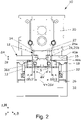
- the stamping press 10 is shown with a retrofit assembly 12 in an assembled state, with the installation space 26 being expanded in the width direction B by a width offset ⁇ B and pressure columns 14 as part of the retrofit assembly 12 receiving a ram 18 widened according to the width offset ⁇ B.
- spacers 16 as part of the retrofit assembly 12, in particular as Spacer blocks are arranged between the machine housing 20 and the guide columns 22, which are offset in the width direction B, to expand the installation space and thus serve as a transition piece.
- This arrangement of the spacer means 16 means that the machine housing 20 is offset upwards by a height offset ⁇ H along the height direction H relative to the guide columns 22, with the retrofittable pressure columns 14 for receiving the ram 18 being lengthened along the height direction H, preferably with a connecting section 24.
- the retrofittable pressure columns 14 preferably have a connecting section 24, which is offset laterally by an offset ⁇ V with respect to a longitudinal axis S of the pressure columns 14 in order to accommodate a widened ram 18 with receiving openings 28 that are also spaced wider at the sides.
- the installation space 26 and the ram 18 are enlarged by a width offset ⁇ B in the width direction B, with a distance V between the receiving openings 28 of the ram 18 being widened by twice the offset ⁇ V of the pressure columns 14, preferably in order to facilitate the introduction of force from the pressure columns 14 into the ram 18 to optimize.
- the height offset ⁇ H also increases an assembly space 27 between the ram 18 and the machine housing 20 in order to accommodate a ram 18 that is enlarged in the width direction B and/or in the height direction H.
- the in the 2 shown spacer means 16 the guide columns 22 in the lateral width direction B such that a projection of a bearing surface 40a of the machine housing 20 in the height direction H at least partially overlaps with an opposite bearing surface 40b of the guide columns 22.
- a bearing surface 40a of the machine housing 20 in the height direction H at least partially overlaps with an opposite bearing surface 40b of the guide columns 22.
- at least one half of the bearing surface 40b overlaps in the width direction B.
- a weight force of the machine housing 20 in a line of action along the height direction H is advantageously at least partially directly absorbed by the guide columns 22 underneath. More preferably, the spacer means 16 are in full contact with the bearing surfaces 40a, 40b of the machine housing 20 and the guide columns 22.
- the lower part 25b also has a corresponding L-shaped recess for positive connection to the upper part 25a. Adjacent to this L-shaped recess, the lower part 25b preferably has a projection 42 such that when the pressure columns 14 are in the assembled state, the cross sections of the two parts 25a, 25b along the longitudinal axis S overlap over the entire area in a connection area, in particular for improved force transmission.
- a connecting section 24, in particular a lower part 25b of the pressure column 14, as a spacer for extending the pressure column 14, as in FIG 4 shown, is formed.
- the pressure columns 14 within the machine housing 20 can also be offset laterally with the first receiving opening 36a in order to accommodate more widely spaced accommodation openings 28 of the ram 18 , and this can also be made possible by the enlarged assembly space 27 below the machine housing 20 .
- the receiving openings 28 of the ram 18 can preferably not be offset with respect to a longitudinal axis S of the pressure columns 14 .
- This embodiment can then be selected if the tappet 18 is manufactured to be adapted to the width offset ⁇ B, in particular in a casting process, without increasing the distance between the receiving openings 28 in the process.
- a geometry of the receiving openings 28 is then adapted to the changed loads in a new design.
- the pressure column 14 has fluid channels 30, in particular for lubricants, which are designed to conduct a fluid preferably through a fluid inlet 31a into the second receiving openings 36b and to discharge it with a fluid return 31b in a circulation flow, in order in particular to reach a bearing point of the to lubricate tappet 18.
- bores 44 in particular partially threaded bores, in order to fix the two parts 25a, 25b to one another by means of a screw connection.
- the spacer means 16 are shown as a spacer block which, in the mounted state, is arranged with an upper side 46a on the bearing surface 40a of the machine housing 20 and with a lower side 46b on the bearing surface 40b of the guide columns 22.
- Bores 44 for screw connections are shown, which are designed for mounting in accordance with existing connection receptacles in the bearing surfaces 40a, 40b of the machine housing 20 and the guide columns 22.
- the upper side 46a and the lower side 46b of the spacer means 16 are preferably designed in such a way that in the assembled state they rest over the entire surface and/or over the entire bearing surfaces 40a, 40b between the machine housing 20 and the guide columns 22 in order to transfer the Distribute forces over as large an area as possible.
- Fluid channels 30 are also preferred in the spacer means 16, as in the cross-sectional views Figures 8e and 8f shown, arranged, which are also arranged for mounting according to existing fluid connections in the bearing surfaces 40a, 40b of the machine housing 20 and the guide columns 22.
- the fluid channels 30 have a branch corresponding to the width offset ⁇ B of the installation space 26 .
- the spacer means 16 preferably also have a fluid supply channel 31a and a fluid return channel 31b in order to conduct a fluid, in particular a lubricant, from the machine housing 20 into the guide supports 22 for lubricating sliding surfaces of the ram 18.
- a width of the spacer means 16 in the width direction B is preferably between 280 mm and 300 mm, particularly preferably 293 mm, and a height, in particular a height offset ⁇ H, in the height direction H is preferably 80mm to 120mm, particularly preferably 100mm.
- the installation space 26 is preferably expanded with a width in the width direction B from originally 540 mm to 640 mm to 790 mm, particularly preferably 790 mm, ie with a width offset ⁇ B of between 100 mm and 250 mm.
- a lateral offset ⁇ V of the pressure columns 14 is preferably 25 mm to 30 mm, preferably based on an original distance V of the pressure columns of 270 mm.
Landscapes
- Engineering & Computer Science (AREA)
- Mechanical Engineering (AREA)
- Presses And Accessory Devices Thereof (AREA)
Applications Claiming Priority (1)
| Application Number | Priority Date | Filing Date | Title |
|---|---|---|---|
| DE102021118918.7A DE102021118918B3 (de) | 2021-07-21 | 2021-07-21 | Nachrüstbaugruppe für eine Stanzpresse, sowie Montageverfahren und Stanzpresse |
Publications (3)
| Publication Number | Publication Date |
|---|---|
| EP4122690A1 true EP4122690A1 (fr) | 2023-01-25 |
| EP4122690C0 EP4122690C0 (fr) | 2024-07-17 |
| EP4122690B1 EP4122690B1 (fr) | 2024-07-17 |
Family
ID=82446531
Family Applications (1)
| Application Number | Title | Priority Date | Filing Date |
|---|---|---|---|
| EP22176089.5A Active EP4122690B1 (fr) | 2021-07-21 | 2022-05-30 | Module de modernisation pour une presse à estamper, ainsi que procédé de montage et presse à estamper |
Country Status (2)
| Country | Link |
|---|---|
| EP (1) | EP4122690B1 (fr) |
| DE (1) | DE102021118918B3 (fr) |
Citations (5)
| Publication number | Priority date | Publication date | Assignee | Title |
|---|---|---|---|---|
| US4502379A (en) * | 1982-07-14 | 1985-03-05 | Aida Engineering Ltd. | Press frame |
| US5349902A (en) * | 1993-04-20 | 1994-09-27 | The Minster Machine Company | Press shutheight adjustment mechanism |
| US5375513A (en) * | 1992-06-27 | 1994-12-27 | L. Schuler Gmbh | Press installation with slides connected at linking points by connecting rods to a press frame |
| DE19953518A1 (de) * | 1999-11-05 | 2001-05-10 | Schoen & Sandt Ag | Stanzmaschine |
| DE102008053561A1 (de) * | 2007-10-30 | 2009-06-18 | Bögle, Michael | Stanzautomat |
-
2021
- 2021-07-21 DE DE102021118918.7A patent/DE102021118918B3/de not_active Expired - Fee Related
-
2022
- 2022-05-30 EP EP22176089.5A patent/EP4122690B1/fr active Active
Patent Citations (6)
| Publication number | Priority date | Publication date | Assignee | Title |
|---|---|---|---|---|
| US4502379A (en) * | 1982-07-14 | 1985-03-05 | Aida Engineering Ltd. | Press frame |
| US5375513A (en) * | 1992-06-27 | 1994-12-27 | L. Schuler Gmbh | Press installation with slides connected at linking points by connecting rods to a press frame |
| US5349902A (en) * | 1993-04-20 | 1994-09-27 | The Minster Machine Company | Press shutheight adjustment mechanism |
| DE19953518A1 (de) * | 1999-11-05 | 2001-05-10 | Schoen & Sandt Ag | Stanzmaschine |
| DE102008053561A1 (de) * | 2007-10-30 | 2009-06-18 | Bögle, Michael | Stanzautomat |
| DE102008053561B4 (de) | 2007-10-30 | 2015-06-18 | Michael Bögle | Stanzautomat |
Also Published As
| Publication number | Publication date |
|---|---|
| DE102021118918B3 (de) | 2022-10-20 |
| EP4122690C0 (fr) | 2024-07-17 |
| EP4122690B1 (fr) | 2024-07-17 |
Similar Documents
| Publication | Publication Date | Title |
|---|---|---|
| DE10329312A1 (de) | Rohrverbindungsstruktur und Verfahren zur Herstellung dieser Struktur | |
| EP3393693B1 (fr) | Mécanisme à clavette | |
| EP1456547B1 (fr) | Arbre creux | |
| DE69216045T2 (de) | Abdichtungsvorrichtungen für geradlinig bewegenden machanismus und verfahren zu deren herstellung | |
| DE10300514A1 (de) | Durchflußwegstruktur eines Hohlrohrs | |
| EP3763970B1 (fr) | Vis à billes, écrou de broche et procédé de fabrication d'un écrou de broche | |
| EP1247596A2 (fr) | Dispositif de guidage pour machine-outils | |
| DE19639677B4 (de) | Verfahren und Vorrichtung zur Herstellung des äußeren Elements eines Universalgelenks mit Kreuznuten | |
| DE102021118918B3 (de) | Nachrüstbaugruppe für eine Stanzpresse, sowie Montageverfahren und Stanzpresse | |
| DE20113561U1 (de) | Werkzeug zum Ein- und Ausbauen von Lagerelementen | |
| EP1907249B1 (fr) | Bequille | |
| WO2009021722A1 (fr) | Élément d'accouplement pour un accouplement entraîneur, et procédé de fabrication | |
| DE3022844A1 (de) | Einrichtung an werkzeugen oder pressen zum ziehen von blechformteilen | |
| EP2358931B1 (fr) | Cylindre supérieur pour un banc d'étirage | |
| EP2142409B1 (fr) | Dispositif de fixation permettant de realiser la jonction d'une carrosserie a un amenagement interieur pour un vehicule sur rail | |
| EP0058828A2 (fr) | Outil à levier à transmission progressive | |
| DE102010041062B4 (de) | Verfahren zum Herstellen einer Gehäuseanordnung, Gehäuseanordnung sowie Stempelvorrichtung | |
| EP3528977B1 (fr) | Colonne de guidage à organe de retenue de cage pour un bâti à guidage par colonnes | |
| EP3855039B1 (fr) | Étrier de frein en fonte | |
| EP4074984A1 (fr) | Bloc hydraulique et procédé | |
| DE10220009B4 (de) | Trägerplatte aus Blech zur Fixierung oder Lagerung von Achsen oder Wellen | |
| DE102012202312A1 (de) | Fluidbefüllbares Elastomerlager | |
| DE102022108067B3 (de) | Werkzeugschieber und Verfahren zum Montieren und/oder Demontieren | |
| DE19713784A1 (de) | Mehrteilige Kolbenstangenführung | |
| DE102005003552B4 (de) | Kreuzkopfmotor |
Legal Events
| Date | Code | Title | Description |
|---|---|---|---|
| PUAI | Public reference made under article 153(3) epc to a published international application that has entered the european phase |
Free format text: ORIGINAL CODE: 0009012 |
|
| STAA | Information on the status of an ep patent application or granted ep patent |
Free format text: STATUS: THE APPLICATION HAS BEEN PUBLISHED |
|
| AK | Designated contracting states |
Kind code of ref document: A1 Designated state(s): AL AT BE BG CH CY CZ DE DK EE ES FI FR GB GR HR HU IE IS IT LI LT LU LV MC MK MT NL NO PL PT RO RS SE SI SK SM TR |
|
| STAA | Information on the status of an ep patent application or granted ep patent |
Free format text: STATUS: REQUEST FOR EXAMINATION WAS MADE |
|
| 17P | Request for examination filed |
Effective date: 20230328 |
|
| RBV | Designated contracting states (corrected) |
Designated state(s): AL AT BE BG CH CY CZ DE DK EE ES FI FR GB GR HR HU IE IS IT LI LT LU LV MC MK MT NL NO PL PT RO RS SE SI SK SM TR |
|
| GRAP | Despatch of communication of intention to grant a patent |
Free format text: ORIGINAL CODE: EPIDOSNIGR1 |
|
| STAA | Information on the status of an ep patent application or granted ep patent |
Free format text: STATUS: GRANT OF PATENT IS INTENDED |
|
| INTG | Intention to grant announced |
Effective date: 20240227 |
|
| GRAS | Grant fee paid |
Free format text: ORIGINAL CODE: EPIDOSNIGR3 |
|
| GRAA | (expected) grant |
Free format text: ORIGINAL CODE: 0009210 |
|
| STAA | Information on the status of an ep patent application or granted ep patent |
Free format text: STATUS: THE PATENT HAS BEEN GRANTED |
|
| AK | Designated contracting states |
Kind code of ref document: B1 Designated state(s): AL AT BE BG CH CY CZ DE DK EE ES FI FR GB GR HR HU IE IS IT LI LT LU LV MC MK MT NL NO PL PT RO RS SE SI SK SM TR |
|
| REG | Reference to a national code |
Ref country code: CH Ref legal event code: EP |
|
| REG | Reference to a national code |
Ref country code: DE Ref legal event code: R096 Ref document number: 502022001239 Country of ref document: DE |
|
| REG | Reference to a national code |
Ref country code: IE Ref legal event code: FG4D Free format text: LANGUAGE OF EP DOCUMENT: GERMAN |
|
| U01 | Request for unitary effect filed |
Effective date: 20240815 |
|
| U07 | Unitary effect registered |
Designated state(s): AT BE BG DE DK EE FI FR IT LT LU LV MT NL PT SE SI Effective date: 20240827 |
|
| PG25 | Lapsed in a contracting state [announced via postgrant information from national office to epo] |
Ref country code: NO Free format text: LAPSE BECAUSE OF FAILURE TO SUBMIT A TRANSLATION OF THE DESCRIPTION OR TO PAY THE FEE WITHIN THE PRESCRIBED TIME-LIMIT Effective date: 20241017 |
|
| PG25 | Lapsed in a contracting state [announced via postgrant information from national office to epo] |
Ref country code: GR Free format text: LAPSE BECAUSE OF FAILURE TO SUBMIT A TRANSLATION OF THE DESCRIPTION OR TO PAY THE FEE WITHIN THE PRESCRIBED TIME-LIMIT Effective date: 20241018 Ref country code: PL Free format text: LAPSE BECAUSE OF FAILURE TO SUBMIT A TRANSLATION OF THE DESCRIPTION OR TO PAY THE FEE WITHIN THE PRESCRIBED TIME-LIMIT Effective date: 20240717 |
|
| PG25 | Lapsed in a contracting state [announced via postgrant information from national office to epo] |
Ref country code: IS Free format text: LAPSE BECAUSE OF FAILURE TO SUBMIT A TRANSLATION OF THE DESCRIPTION OR TO PAY THE FEE WITHIN THE PRESCRIBED TIME-LIMIT Effective date: 20241117 |
|
| PG25 | Lapsed in a contracting state [announced via postgrant information from national office to epo] |
Ref country code: HR Free format text: LAPSE BECAUSE OF FAILURE TO SUBMIT A TRANSLATION OF THE DESCRIPTION OR TO PAY THE FEE WITHIN THE PRESCRIBED TIME-LIMIT Effective date: 20240717 |
|
| PG25 | Lapsed in a contracting state [announced via postgrant information from national office to epo] |
Ref country code: ES Free format text: LAPSE BECAUSE OF FAILURE TO SUBMIT A TRANSLATION OF THE DESCRIPTION OR TO PAY THE FEE WITHIN THE PRESCRIBED TIME-LIMIT Effective date: 20240717 Ref country code: RS Free format text: LAPSE BECAUSE OF FAILURE TO SUBMIT A TRANSLATION OF THE DESCRIPTION OR TO PAY THE FEE WITHIN THE PRESCRIBED TIME-LIMIT Effective date: 20241017 |
|
| PG25 | Lapsed in a contracting state [announced via postgrant information from national office to epo] |
Ref country code: RS Free format text: LAPSE BECAUSE OF FAILURE TO SUBMIT A TRANSLATION OF THE DESCRIPTION OR TO PAY THE FEE WITHIN THE PRESCRIBED TIME-LIMIT Effective date: 20241017 Ref country code: PL Free format text: LAPSE BECAUSE OF FAILURE TO SUBMIT A TRANSLATION OF THE DESCRIPTION OR TO PAY THE FEE WITHIN THE PRESCRIBED TIME-LIMIT Effective date: 20240717 Ref country code: NO Free format text: LAPSE BECAUSE OF FAILURE TO SUBMIT A TRANSLATION OF THE DESCRIPTION OR TO PAY THE FEE WITHIN THE PRESCRIBED TIME-LIMIT Effective date: 20241017 Ref country code: IS Free format text: LAPSE BECAUSE OF FAILURE TO SUBMIT A TRANSLATION OF THE DESCRIPTION OR TO PAY THE FEE WITHIN THE PRESCRIBED TIME-LIMIT Effective date: 20241117 Ref country code: HR Free format text: LAPSE BECAUSE OF FAILURE TO SUBMIT A TRANSLATION OF THE DESCRIPTION OR TO PAY THE FEE WITHIN THE PRESCRIBED TIME-LIMIT Effective date: 20240717 Ref country code: GR Free format text: LAPSE BECAUSE OF FAILURE TO SUBMIT A TRANSLATION OF THE DESCRIPTION OR TO PAY THE FEE WITHIN THE PRESCRIBED TIME-LIMIT Effective date: 20241018 Ref country code: ES Free format text: LAPSE BECAUSE OF FAILURE TO SUBMIT A TRANSLATION OF THE DESCRIPTION OR TO PAY THE FEE WITHIN THE PRESCRIBED TIME-LIMIT Effective date: 20240717 |
|
| PG25 | Lapsed in a contracting state [announced via postgrant information from national office to epo] |
Ref country code: SM Free format text: LAPSE BECAUSE OF FAILURE TO SUBMIT A TRANSLATION OF THE DESCRIPTION OR TO PAY THE FEE WITHIN THE PRESCRIBED TIME-LIMIT Effective date: 20240717 |
|
| PG25 | Lapsed in a contracting state [announced via postgrant information from national office to epo] |
Ref country code: CZ Free format text: LAPSE BECAUSE OF FAILURE TO SUBMIT A TRANSLATION OF THE DESCRIPTION OR TO PAY THE FEE WITHIN THE PRESCRIBED TIME-LIMIT Effective date: 20240717 |
|
| PG25 | Lapsed in a contracting state [announced via postgrant information from national office to epo] |
Ref country code: SK Free format text: LAPSE BECAUSE OF FAILURE TO SUBMIT A TRANSLATION OF THE DESCRIPTION OR TO PAY THE FEE WITHIN THE PRESCRIBED TIME-LIMIT Effective date: 20240717 |
|
| PLBE | No opposition filed within time limit |
Free format text: ORIGINAL CODE: 0009261 |
|
| STAA | Information on the status of an ep patent application or granted ep patent |
Free format text: STATUS: NO OPPOSITION FILED WITHIN TIME LIMIT |
|
| 26N | No opposition filed |
Effective date: 20250422 |
|
| U20 | Renewal fee for the european patent with unitary effect paid |
Year of fee payment: 4 Effective date: 20250521 |
|
| PGFP | Annual fee paid to national office [announced via postgrant information from national office to epo] |
Ref country code: CH Payment date: 20250601 Year of fee payment: 4 |
|
| PG25 | Lapsed in a contracting state [announced via postgrant information from national office to epo] |
Ref country code: MC Free format text: LAPSE BECAUSE OF FAILURE TO SUBMIT A TRANSLATION OF THE DESCRIPTION OR TO PAY THE FEE WITHIN THE PRESCRIBED TIME-LIMIT Effective date: 20240717 |
|
| PG25 | Lapsed in a contracting state [announced via postgrant information from national office to epo] |
Ref country code: IE Free format text: LAPSE BECAUSE OF NON-PAYMENT OF DUE FEES Effective date: 20250530 |
|
| PG25 | Lapsed in a contracting state [announced via postgrant information from national office to epo] |
Ref country code: RO Free format text: LAPSE BECAUSE OF FAILURE TO SUBMIT A TRANSLATION OF THE DESCRIPTION OR TO PAY THE FEE WITHIN THE PRESCRIBED TIME-LIMIT Effective date: 20240717 |