EP4123085A1 - Vorrichtung zur behandlung von kleidung - Google Patents
Vorrichtung zur behandlung von kleidung Download PDFInfo
- Publication number
- EP4123085A1 EP4123085A1 EP21771427.8A EP21771427A EP4123085A1 EP 4123085 A1 EP4123085 A1 EP 4123085A1 EP 21771427 A EP21771427 A EP 21771427A EP 4123085 A1 EP4123085 A1 EP 4123085A1
- Authority
- EP
- European Patent Office
- Prior art keywords
- tub
- drum
- rpm
- treatment apparatus
- clothing treatment
- Prior art date
- Legal status (The legal status is an assumption and is not a legal conclusion. Google has not performed a legal analysis and makes no representation as to the accuracy of the status listed.)
- Pending
Links
Images



Classifications
-
- D—TEXTILES; PAPER
- D06—TREATMENT OF TEXTILES OR THE LIKE; LAUNDERING; FLEXIBLE MATERIALS NOT OTHERWISE PROVIDED FOR
- D06F—LAUNDERING, DRYING, IRONING, PRESSING OR FOLDING TEXTILE ARTICLES
- D06F33/00—Control of operations performed in washing machines or washer-dryers
- D06F33/50—Control of washer-dryers characterised by the purpose or target of the control
- D06F33/52—Control of the operational steps, e.g. optimisation or improvement of operational steps depending on the condition of the laundry
- D06F33/63—Control of the operational steps, e.g. optimisation or improvement of operational steps depending on the condition of the laundry of air flow, e.g. blowing air during the washing process to prevent entanglement of the laundry
-
- D—TEXTILES; PAPER
- D06—TREATMENT OF TEXTILES OR THE LIKE; LAUNDERING; FLEXIBLE MATERIALS NOT OTHERWISE PROVIDED FOR
- D06F—LAUNDERING, DRYING, IRONING, PRESSING OR FOLDING TEXTILE ARTICLES
- D06F34/00—Details of control systems for washing machines, washer-dryers or laundry dryers
- D06F34/10—Power supply arrangements, e.g. stand-by circuits
-
- D—TEXTILES; PAPER
- D06—TREATMENT OF TEXTILES OR THE LIKE; LAUNDERING; FLEXIBLE MATERIALS NOT OTHERWISE PROVIDED FOR
- D06F—LAUNDERING, DRYING, IRONING, PRESSING OR FOLDING TEXTILE ARTICLES
- D06F34/00—Details of control systems for washing machines, washer-dryers or laundry dryers
- D06F34/14—Arrangements for detecting or measuring specific parameters
- D06F34/26—Condition of the drying air, e.g. air humidity or temperature
-
- D—TEXTILES; PAPER
- D06—TREATMENT OF TEXTILES OR THE LIKE; LAUNDERING; FLEXIBLE MATERIALS NOT OTHERWISE PROVIDED FOR
- D06F—LAUNDERING, DRYING, IRONING, PRESSING OR FOLDING TEXTILE ARTICLES
- D06F58/00—Domestic laundry dryers
- D06F58/20—General details of domestic laundry dryers
- D06F58/26—Heating arrangements, e.g. gas heating equipment
- D06F58/263—Gas heating equipment
-
- D—TEXTILES; PAPER
- D06—TREATMENT OF TEXTILES OR THE LIKE; LAUNDERING; FLEXIBLE MATERIALS NOT OTHERWISE PROVIDED FOR
- D06F—LAUNDERING, DRYING, IRONING, PRESSING OR FOLDING TEXTILE ARTICLES
- D06F58/00—Domestic laundry dryers
- D06F58/32—Control of operations performed in domestic laundry dryers
- D06F58/34—Control of operations performed in domestic laundry dryers characterised by the purpose or target of the control
- D06F58/36—Control of operational steps, e.g. for optimisation or improvement of operational steps depending on the condition of the laundry
- D06F58/38—Control of operational steps, e.g. for optimisation or improvement of operational steps depending on the condition of the laundry of drying, e.g. to achieve the target humidity
-
- H—ELECTRICITY
- H05—ELECTRIC TECHNIQUES NOT OTHERWISE PROVIDED FOR
- H05B—ELECTRIC HEATING; ELECTRIC LIGHT SOURCES NOT OTHERWISE PROVIDED FOR; CIRCUIT ARRANGEMENTS FOR ELECTRIC LIGHT SOURCES, IN GENERAL
- H05B6/00—Heating by electric, magnetic or electromagnetic fields
- H05B6/02—Induction heating
- H05B6/10—Induction heating apparatus, other than furnaces, for specific applications
-
- H—ELECTRICITY
- H05—ELECTRIC TECHNIQUES NOT OTHERWISE PROVIDED FOR
- H05B—ELECTRIC HEATING; ELECTRIC LIGHT SOURCES NOT OTHERWISE PROVIDED FOR; CIRCUIT ARRANGEMENTS FOR ELECTRIC LIGHT SOURCES, IN GENERAL
- H05B6/00—Heating by electric, magnetic or electromagnetic fields
- H05B6/02—Induction heating
- H05B6/10—Induction heating apparatus, other than furnaces, for specific applications
- H05B6/105—Induction heating apparatus, other than furnaces, for specific applications using a susceptor
- H05B6/108—Induction heating apparatus, other than furnaces, for specific applications using a susceptor for heating a fluid
-
- H—ELECTRICITY
- H05—ELECTRIC TECHNIQUES NOT OTHERWISE PROVIDED FOR
- H05B—ELECTRIC HEATING; ELECTRIC LIGHT SOURCES NOT OTHERWISE PROVIDED FOR; CIRCUIT ARRANGEMENTS FOR ELECTRIC LIGHT SOURCES, IN GENERAL
- H05B6/00—Heating by electric, magnetic or electromagnetic fields
- H05B6/02—Induction heating
- H05B6/36—Coil arrangements
- H05B6/42—Cooling of coils
-
- D—TEXTILES; PAPER
- D06—TREATMENT OF TEXTILES OR THE LIKE; LAUNDERING; FLEXIBLE MATERIALS NOT OTHERWISE PROVIDED FOR
- D06F—LAUNDERING, DRYING, IRONING, PRESSING OR FOLDING TEXTILE ARTICLES
- D06F2103/00—Parameters monitored or detected for the control of domestic laundry washing machines, washer-dryers or laundry dryers
- D06F2103/02—Characteristics of laundry or load
- D06F2103/04—Quantity, e.g. weight or variation of weight
-
- D—TEXTILES; PAPER
- D06—TREATMENT OF TEXTILES OR THE LIKE; LAUNDERING; FLEXIBLE MATERIALS NOT OTHERWISE PROVIDED FOR
- D06F—LAUNDERING, DRYING, IRONING, PRESSING OR FOLDING TEXTILE ARTICLES
- D06F2103/00—Parameters monitored or detected for the control of domestic laundry washing machines, washer-dryers or laundry dryers
- D06F2103/18—Washing liquid level
-
- D—TEXTILES; PAPER
- D06—TREATMENT OF TEXTILES OR THE LIKE; LAUNDERING; FLEXIBLE MATERIALS NOT OTHERWISE PROVIDED FOR
- D06F—LAUNDERING, DRYING, IRONING, PRESSING OR FOLDING TEXTILE ARTICLES
- D06F2103/00—Parameters monitored or detected for the control of domestic laundry washing machines, washer-dryers or laundry dryers
- D06F2103/38—Time, e.g. duration
-
- D—TEXTILES; PAPER
- D06—TREATMENT OF TEXTILES OR THE LIKE; LAUNDERING; FLEXIBLE MATERIALS NOT OTHERWISE PROVIDED FOR
- D06F—LAUNDERING, DRYING, IRONING, PRESSING OR FOLDING TEXTILE ARTICLES
- D06F2105/00—Systems or parameters controlled or affected by the control systems of washing machines, washer-dryers or laundry dryers
- D06F2105/14—Temperature of laundry
-
- D—TEXTILES; PAPER
- D06—TREATMENT OF TEXTILES OR THE LIKE; LAUNDERING; FLEXIBLE MATERIALS NOT OTHERWISE PROVIDED FOR
- D06F—LAUNDERING, DRYING, IRONING, PRESSING OR FOLDING TEXTILE ARTICLES
- D06F2105/00—Systems or parameters controlled or affected by the control systems of washing machines, washer-dryers or laundry dryers
- D06F2105/46—Drum speed; Actuation of motors, e.g. starting or interrupting
-
- D—TEXTILES; PAPER
- D06—TREATMENT OF TEXTILES OR THE LIKE; LAUNDERING; FLEXIBLE MATERIALS NOT OTHERWISE PROVIDED FOR
- D06F—LAUNDERING, DRYING, IRONING, PRESSING OR FOLDING TEXTILE ARTICLES
- D06F25/00—Washing machines with receptacles, e.g. perforated, having a rotary movement, e.g. oscillatory movement, the receptacle serving both for washing and for centrifugally separating water from the laundry and having further drying means, e.g. using hot air
-
- D—TEXTILES; PAPER
- D06—TREATMENT OF TEXTILES OR THE LIKE; LAUNDERING; FLEXIBLE MATERIALS NOT OTHERWISE PROVIDED FOR
- D06F—LAUNDERING, DRYING, IRONING, PRESSING OR FOLDING TEXTILE ARTICLES
- D06F33/00—Control of operations performed in washing machines or washer-dryers
- D06F33/50—Control of washer-dryers characterised by the purpose or target of the control
- D06F33/52—Control of the operational steps, e.g. optimisation or improvement of operational steps depending on the condition of the laundry
- D06F33/63—Control of the operational steps, e.g. optimisation or improvement of operational steps depending on the condition of the laundry of air flow, e.g. blowing air during the washing process to prevent entanglement of the laundry
- D06F33/64—Unheated air
-
- D—TEXTILES; PAPER
- D06—TREATMENT OF TEXTILES OR THE LIKE; LAUNDERING; FLEXIBLE MATERIALS NOT OTHERWISE PROVIDED FOR
- D06F—LAUNDERING, DRYING, IRONING, PRESSING OR FOLDING TEXTILE ARTICLES
- D06F39/00—Details of washing machines not specific to a single type of machines covered by groups D06F9/00 - D06F27/00
- D06F39/04—Heating arrangements
-
- D—TEXTILES; PAPER
- D06—TREATMENT OF TEXTILES OR THE LIKE; LAUNDERING; FLEXIBLE MATERIALS NOT OTHERWISE PROVIDED FOR
- D06F—LAUNDERING, DRYING, IRONING, PRESSING OR FOLDING TEXTILE ARTICLES
- D06F58/00—Domestic laundry dryers
- D06F58/20—General details of domestic laundry dryers
- D06F58/26—Heating arrangements, e.g. gas heating equipment
- D06F58/266—Microwave heating equipment
Definitions
- clothing treatment apparatuses may include a washing machine, a dryer, a device for refreshing clothes, and the like.
- the washing machine may be a washing machine with a drying function.
- a coil is wound on an induction heating module provided in a clothing treatment apparatus such as a washing machine or dryer, and heat may be transferred to an object to be heated (drum) by an induced current generated upon application of a current to the coil.
- An aspect of the present disclosure provides a clothing treatment apparatus, such as a dryer, a washing machine, an integrated washer-dryer, or an apparatus for refreshing clothes, which is capable of improving drying performance by controlling rotation of a drum.
- a clothing treatment apparatus such as a dryer, a washing machine, an integrated washer-dryer, or an apparatus for refreshing clothes, which is capable of improving drying performance by controlling rotation of a drum.
- Yet another object of the present disclosure provides a clothing treatment apparatus capable of improving drying performance by generating discharge and introduction of air at least once in a section where an RPM of the drum is increased and/or decreased.
- Yet another object of the present disclosure provides a clothing treatment apparatus capable of improving drying quality by controlling rotation of a drum in a clothing treatment apparatus provided with an induction module.
- a clothing treatment apparatus may use resonance of a tub to discharge wet internal air and introduce dry external air, thereby improving drying performance.
- a clothing treatment apparatus may cause air to be discharged and introduced at least once in a section where an RPM of the drum is increases and/or decreased, thereby improving drying performance.
- the drum In response to the RPM of the drum reaching the target RPM, the drum may be driven at the target RPM for a predetermined time, and after the predetermined time passes, the RPM of the drum may be decreased.
- An RPM increase rate in a section where the RPM of the drum is increased may be smaller than an RPM decrease rate in a section where the RPM of the drum is decreased.
- the driver may rotate the drum so that an RPM of the drum is increased to a target RPM after an operation of the induction module is terminated, or the driver may rotate the drum so that an RPM of the drum is increased to the target RPM when the induction module is not operated.
- the target RPM may be higher than an RPM at which the clothes rotate while closely contacting an inner circumferential surface of the drum.
- the tub support part may include a first support part fixed to an upper surface of the cabinet, and a second support part fixed to a lower surface of the cabinet, and the second support part may include the hinge shaft.
- the induction module may be spaced apart from the drum.
- the induction module may be installed at the tub.
- the induction module may be fixed to the tub.
- the induction module In a clothing treatment apparatus without a tub, such as a dryer, the induction module may be disposed inside a case or on an inner wall of the case.
- the induction module may be disposed at a position spaced apart from the drum at an upper, lower side, left, or right side of the drum inside the case.
- the induction module may generate a magnetic field.
- the induction module heats the drum using a magnetic field.
- the drum may include a body in a cylindrical shape and a through hole formed in the body.
- the clothing treatment apparatus may further include a controller configured to control operations of the driver and the induction module.
- the communication part may include a cabinet communication part connected to the cabinet, a tub communication part connected to an inside of the tub, and a bellows part connecting the cabinet communication part and the tub communication part.
- a clothing treatment device in which the outside of the cabinet and the inside of the tub communicate with each other to discharge moisture-contained air and provide dry air, based on a fact that the tub vibrates greatly due to resonance during a process of increasing a rotational speed when there is an unbalanced mass in the drum.
- a control method of a clothing treatment apparatus that increases a rotation speed of a drum to an RPM at which excessive vibration of the tub occurs and changing the rotation speed back to a normal rotation speed when the target RPM is reached.
- a clothing treatment apparatus for improving drying performance by controlling turning on/off of a coolant supply valve while an induction module is operated, so that the coolant supply valve is always open while the induction module is not operated, thereby improving drying performance, and a control method thereof.
- a clothing treatment apparatus in which a step of vibrating a tub is repeatedly performed, and a control method thereof.
- a control method of a clothing treatment apparatus which includes: a cabinet provided with an inlet port through which clothes are introduced; a tub provided in the cabinet and having a tub inlet part through which the clothes are introduced; a drum rotatably provided in the tub and accommodating the clothes; a driver for rotating the drum; an induction module for heating the drum; a gasket connecting the inlet port and the tub inlet part and provided to be stretchable; and a communication part for communicating an inside of the tub and an outside of the cabinet, and the method includes a drying step in the clothing treatment apparatus may include at least one of the following: an induction operating step in which the induction module is operated; and a tub vibrating step in which the tub vibrates back and forth in a longitudinal direction of the tub in response to rotation of the drum, and the tub vibrating step may include: an RPM increasing step in which an RPM of the drum is increased to a target RPM at which there is at least one section where the tub is able to resonate in response to the rotation RPM of the drum;
- the induction operating step and the tub vibrating step provide a control method of the clothing treatment apparatus is performed at the same time.
- a method for controlling a clothing treatment apparatus in which a coolant input amount is adjusted through opening and closing of a coolant water supply valve for introducing coolant into the tub when the induction operating step and the tub vibrating step are performed together.
- the tub vibrating step provides a method of controlling a clothing treatment apparatus that is started after the induction operating step is terminated or is performed without the induction operating step proceeding.
- the target RPM is 360 RPM to 440 RPM to provide a control method of the clothing treatment apparatus.
- the target RPM is set to be higher than the RPM in a spin-drying cycle in which the clothes are brought into close contact with the inner circumferential surface of the drum to remove moisture.
- a control method of a clothing treatment apparatus in which the tub supports are provided with a hinge shaft so that the tub vibrates in a longitudinal direction of the cabinet when the tub resonates in response to rotation of the drum, and the tub is controlled to vibrate more in the longitudinal direction of the cabinet in the RPM increasing step and the RPM decreasing step than in a transverse direction of the cabinet.
- a clothing treatment apparatus which comprises: a cabinet provided with an inlet port through which clothes are introduced; a tub provided in the cabinet and having a tub inlet part through which the clothes are introduced; a drum rotatably provided in the tub and accommodating the clothes; a driver for rotating the drum; an induction module for heating the drum; a gasket connecting the inlet port and the tub inlet part and provided to be stretchable; a communication part for communicating an inside of the tub and an outside of the cabinet; and a controller configured to control operations of the driver and the induction module, and the controller controls the induction module and the driver to perform at least one of operating the induction module and vibrating the tub by adjusting a rotational speed of the drum during drying of clothes, the driver is controlled to increase an RPM of the drum to a target RPM at which there is at least one a section where the tub is able to resonate to correspond to a rotational RPM of the drum, and the driver is controlled to be driven at the target RPM for a predetermined time when the target RPM
- a clothing treatment apparatus in which the controller sequentially and repeatedly perform a control so that an RPM of the drum is increased to the target RPM, maintained, and decreased.
- a clothing treatment apparatus in which the controller simultaneously controls the operation of the induction module and the operation of the driver.
- a clothing treatment apparatus in which when the induction module and the driver are operated together, the controller performs a control so that an amount of coolant to be added is controlled by opening and closing the coolant supply valve for adding coolant into the tub.
- a clothing treatment apparatus in which the operation of the driver is started after termination of the operation of the induction module or is performed without the operation of the induction module.
- a clothing treatment apparatus in which the controller controls the coolant supply valve, which is for adding coolant into the tub, to be continuously open while controlling the operation of the driver.
- a clothing treatment apparatus in which the target RPM is higher than an RPM in a spin-drying cycle where moisture is to be removed by causing clothes to be adhered to an inner circumferential surface of the drum.
- a clothing treatment apparatus in which the tub support parts are provided with a hinge shaft so that the tub vibrates in a longitudinal direction of the cabinet when the tub resonates in response to rotation of the drum.
- a volume of a tub internal space changes when the tub is moved in a front-rear direction of a cabinet as the tub resonates in response to rotation of a drum, it is possible to naturally discharge moisture-contained air and suck in dry air, thereby removing moisture-contained air in a tub internal space.
- an absolute humidity of a tub internal space may decrease compared to when the tub does not vibrate. Accordingly, it is possible to improve drying performance.
- a clothing treatment apparatus and a control method thereof according to an embodiment of the present disclosure will be described in detail with reference to the accompanying drawings.
- a washing machine will be described as a representative example of a clothing treatment apparatus of the present disclosure.
- the clothing treatment apparatus of the present disclosure is not limited thereto.
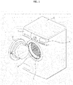
- FIG. 1 is a view showing an external appearance of a clothing treatment apparatus according to an embodiment of the present disclosure
- FIG. 2 is a view showing an internal configuration of the clothing treatment apparatus shown in FIG. 1 .
- a direction toward a door 12 with respect to a center of the clothing treatment apparatus may be defined as a front direction.
- a direction opposite to the direction toward the door 12 may be defined as a rear direction, and directions to the right and left may be defined depending on the front-rear direction defined above.
- a clothing treatment apparatus may include a cabinet 1 forming an outer appearance of the clothing treatment apparatus, a tub 2 provided inside the cabinet 1, and a drum 3 rotatably provided inside the tub 2 to accommodate an object (for example, a laundry object, an object to be dried, an object to be refreshed).
- an object for example, a laundry object, an object to be dried, an object to be refreshed.
- the clothes when clothes are to be washed with washing water, the clothes may be called a laundry object, when wet clothes are to be dried using heat, the clothes may be called an object to be dried, and when dry clothes are to be refreshed using hot air, cold air, or steam, the clothes may be called an object to be refreshed. Therefore, clothes may be washed, dried, or refreshed with the drum 3 of the clothing treatment apparatus.
- the cabinet 1 may include an inlet port provided at a front of the cabinet 1 through which an object enters and exits, and the cabinet 1 may be provided with the door 12 that is rotatably connected to the cabinet 1 to open and close the inlet port.
- the door 12 may include an annular door frame 121 and a view window 122 provided in a central portion of the door frame 121.
- a detergent box 7 may be provided at an upper front side of the clothing treatment apparatus. Detergent, fabric softener, and the like may be supplied through the detergent box 7.
- the detergent box 7 may be provided with a handle so that a user can slide the detergent box 7 toward the front of the cabinet 1 so as to open and close.
- a control panel 5 may be provided at the upper front side of the clothing treatment apparatus.
- the control panel 5 may be provided for a user interface.
- a user's various inputs may be carried out, and information according to the input or various types of information on the clothing treatment apparatus may be displayed. That is, the control panel 5 may include a manipulation part for a user's manipulation and a display to display information to the user.
- the tub 2 forms a space in a cylindrical shape having a longitudinal axis parallel to or at a predetermined angle relative to a lower surface of the cabinet 1 so as to store water, and a tub opening 21 is provided at a front of the tub 2 so as to communicate with the inlet port.
- the tub 2 may include the tub opening 21 and a tub body 22 constituting the body of the tub. Therefore, the tub body 22 may be provided in a cylindrical shape, and the tub opening 21 may be provided to correspond to a shape of the tub body 22.
- the tub 2 may be installed in the cabinet 1 by tub support parts 131 and 132.
- the tub support parts 131 and 132 may include a first support part 131 and a second support part 132.
- a first support part 131 fixed to an upper surface of the cabinet 1 may be connected to an upper surface of the tub 2. Vibration generated in the tub 2 and transmitted to the cabinet 1 may be damped by the first support part 131.
- the tub 2 may be fixed to a lower surface (bottom surface) of the cabinet 1 by the second support part 132, and the second support part 132 may be provided with a support bar 1321 and a damper 1322 so that vibration generated by rotation of the drum 3 in the tub 2 may be damped.
- the support bar 1321 and the damper 1322 may be provided in pair and may be connected to the tub 2.
- the support bar 1321 and the damper 1322 may be provided as one body.
- the support bar 1321 and the damper 1322 may be provided in pair to be spaced apart from each other with respect to a transverse direction of the tub 2 or a transverse direction of the cabinet 1.
- the support bar 1321 may be provided to be rotatable with respect to a longitudinal direction of the cabinet 1. That is, the tub 2 may vibrate more in the longitudinal direction of the cabinet 1 than in the transverse direction of the cabinet 1.
- the support bar 1321 may be provided with a hinge shaft h so as to be able to rotate in a front-rear direction of the cabinet 1. That is, a hinge shaft h may be provided so that the tub support parts 131 and 132 can be supported inside the cabinet even when the tub 2 vibrates in the front and rear directions of the cabinet 1.
- the tub 2 may be supported inside the cabinet 1 by the first support part 131 and the second support part 132, and the vibration generated from the tub 2 may be damped.
- the drum 3 is provided in a cylindrical shape with a longitudinal axis parallel to or at a predetermined angle relative to the lower surface (bottom surface) of the cabinet 1 so as to accommodate an object, and a drum opening 31 communicating with the tub opening 21 may be provided at a front of the drum 3.
- An angle by a central axis of the tub 2 relative to the bottom surface and an angle by a central axis of the drum 3 relative to the bottom surface may be the same. That is, the predetermined angle may mean the same angle.
- the drum 3 may include a body in a cylindrical shape and a through hole 33 formed in the body.
- a plurality of through holes 33 penetrating the drum 3 may be formed in an outer circumferential surface of the drum 3. Through the through hole 33, air and washing water may be introduced between the inside of the drum 3 and the inside of the tub 2.
- a lifter 35 for agitating an object when the drum 3 rotates may be provided in an inner circumferential surface of the drum 3.
- the lifter 35 may extend along a longitudinal direction of the drum 3 from an inner circumferential surface of the drum 3 and may be provided in plurality on the inner circumferential surface of the drum 3.
- the drum 3 may be rotated by a driver 6 provided at the rear of the tub 2.
- the driver 6 may include a stator 61 fixed to a rear surface of the tub 2, a rotor 63 rotating by an electromagnetic interaction with the stator, and a rotational shaft 65 passing through the rear surface of the tub 2 to connect the drum 3 and the rotor 63.
- the stator 61 may be fixed to a rear surface of a bearing housing 66 provided in the rear surface of the tub 2, and the rotor 63 may include a rotor magnet 632 provided radially outside of the stator 61 and a rotor housing 631 connecting the rotor magnet 632 and the rotational shaft 65.
- a plurality of bearings 68 to support the rotational shaft 65 may be provided inside the bearing housing 66.
- a spider 67 to easily transmit a rotational force of the rotor 63 to the drum 3 may be provided at a rear surface of the drum 3, and the rotational shaft 65 to transmit the rotational force of the rotor 63 may be fixed to the spider 67.
- the clothing treatment apparatus may include a water supply hose 70 to receive water from an outside, and the water supply hose 70 forms a flow path for supplying water to the tub 2.
- cooling of the air may be performed on the inner circumferential surface of the tub 20 and moisture may be condensed and discharged.
- drying may be performed on its own by condensing moisture.
- Coolant may be supplied into the tub 20 to more effectively perform moisture condensation so as to improve drying efficiency.
- the coolant may be introduced through the water supply hose 70.
- a valve 70a may be disposed at the water supply hose 70 to open and close the water supply hose 70.
- the water supply hose 70 may be referred to as a coolant hose for supplying the coolant
- the valve 70a disposed in the water supply hose 70 may be referred to as a coolant supply valve.
- the coolant is supplied while the coolant supply valve 70a is open (ON), and the supply thereof is cut off after the coolant supply valve 70a is closed (OFF).
- the coolant hose and the water supply valve for supplying the coolant may be provided separately from the water supply hose 70.
- the coolant may be supplied while being widely spread from the rear surface or one side or both sides of the tub 20. Through this supply of the coolant, the coolant may flow along an inner surface of the tub 20, thereby prevented from being introduced into the drum.
- the clothing treatment apparatus may include a drainage 14 for discharging water inside the tub 2 to the outside of the cabinet 1.
- the drainage 14 may include a drain pipe 142 forming a drain passage through which water in the tub 1 moves, and a drain pump 141 generating a pressure difference inside the drain pipe 142 so that water can be drained through the drain pipe 142.
- the drain pipe 142 may include a first drain pipe 1421 connecting the lower surface of the tub 2 and the drain pump 141, and a second drain pipe 1422 having one end connected to the drain pump 141 to form a flow path through which water moves outside of the cabinet 1.
- a gasket 13 may be provided between the inlet port of the cabinet 1 and the tub opening 21.
- the gasket 13 connects the tub opening 21 and the inlet port 11 provided in the cabinet 1.
- the gasket 13 prevents a problem that the water inside the tub 2 leaks into the cabinet 1 and the vibration of the tub 2 is transmitted to the cabinet 1.
- the gasket 4 may be stretchable so that airtightness can be secured when the tub 2 vibrates in the longitudinal direction of the cabinet 1. However, the airtightness does not mean a completely sealed state, and the gasket 4 may be provided in such a way that allows air to move when the gasket 4 and the tub 2 are connected.
- air may be introduced through the inlet port 12 of the cabinet 1.
- a plurality of temperature sensors 133a and 133b may be provided in the tub 2.
- the temperature sensors may measure temperature inside the tub 2.
- An upper temperature sensor 133a may be positioned at an upper part of the tub 2 to measure temperature of air heated by the induction module 8.
- a lower temperature sensor 133b may be positioned at a lower part of the tub 2 to sense temperature of washing water or moisture-contained air. That is, the plurality of temperature sensors may sense whether air is heated to a target temperature by the induction module 8.
- the induction module 8 may be controlled by a controller 9 to be described later based on temperatures measured by the temperature sensors.
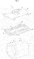
- FIG. 3 is an exploded perspective view of an induction module of the clothing treatment apparatus according to the present embodiment.
- a clothing treatment apparatus may include an induction module 8 for heating a drum 3.
- the induction module 8 may heat the drum 3 in order to heat washing water or dry laundry.
- the induction module 8 may inductively heat the drum 3.
- the principle on how to heat the drum 3 using the induction module 8 is as follows.
- the induction module 8 may be mounted on an outer circumferential surface of a tub 2.
- the induction module 80 may generate a magnetic field as a current is applied to a coil 81 on which a wire is wound.
- the induction module 8 serves to heat a circumferential surface of the drum 3 through the generated magnetic field.
- the wire may include a core wire and a coating surrounding the core wire.
- the core wire may be a single core wire. Of course, a plurality of core wires may be entangled to form one core wire. Therefore, a thickness or wire diameter of the wire may be determined by a thickness of the core wire and the coating.
- the coil 81 may forms a radial alternating magnetic field according to the Ampere's circuit law.
- the alternating magnetic field is concentrated toward the drum (metal material) formed of a conductor having high magnetic permeability.
- the magnetic permeability refers to the degree of magnetization that a material obtains in response to a given magnetic field.
- an eddy current is formed in the drum 3, and the eddy current flows through the drum 3 formed of a conductor and is then converted into Joule heat by the resistance of the drum 3 itself, so that an inner wall of the drum 3 is directly heated.
- the induction module 8 may include a coil 81, a base housing 82, and a module cover 83.
- the induction module 8 may be provided at an outer surface of the tub 2 and may heat the drum 3 through a magnetic field generated upon application of a current to the coil 81.
- the induction module 8 may be provided on the tub 2.
- the induction module 8 may be fixed to the tub 2.
- the induction module 8 may be spaced apart from the drum 3.
- a clothing treatment apparatus such as a dryer may not include the tub 2.
- a configuration applied to the tub 2 in the present specification may apply to the drum 3.
- the induction module 8 may be disposed inside a case or on an inner wall.
- the induction module 8 may be disposed at a position spaced apart from the drum 3 at an upper, lower side, left, or right side of the drum 3 inside the case.
- the induction module 8 may be positioned outside above the drum 3.
- the induction module 8 may include a base housing 82 spaced apart from an outer surface of the tub 2 by a predetermined interval.
- the base housing 82 may be provided to receive and support a wound shape of the coil 81.
- the base housing 82 may be provided in a shape corresponding to an outer circumferential surface (a circumferential surface) of the tub 2 so as to be evenly spaced apart from the tub at a predetermined distance.
- an amount of magnetic field transmitted through the base housing 82 does not vary depending on the position of the circumferential surface of the tub 2, so that uniform heating is possible.
- the tub 2 may be provided with a tub connection part 22.
- the tub connection part 22 may be provided to fix the induction module 8 to the circumferential surface of the tub 2.
- the base housing 82 and the tub 2 may be spaced apart by a length of the tub connection part 22.
- a housing connection part 821 may be provided in the base housing 82 to correspond to the position of the tub connection part 22.
- the tub connection part 22 and the housing connection part 821 may be combined to fix the induction module 8 to the outer circumferential surface of the tub 2.
- the coil 81 may be wound in the base housing 82.
- the coil 81 may be wound along an upper surface of the base housing 82 and may be a little shorter than a predetermined length than the length of the tub 2.
- the coil 81 may be wound at a position close to a front surface of the tub 2 and a rear surface of the tub 2.
- the module cover 83 may be provided at an upper surface of the coil 81 to correspond to a size of the base housing 82.
- the module cover 83 may be coupled to the base housing 82 and mounted on the outer circumferential surface of the tub 2.
- the module cover 83 may include a cooling flow path connection part 832 provided to communicate with a module cooling duct 755 to be described later.
- a cooling flow path connection part 832 provided to communicate with a module cooling duct 755 to be described later.
- the drawings show that the cooling flow path connection part 832 is disposed at a center of the module cover 83, the present disclosure is not limited thereto.
- the cooling flow path connection part 832 may be formed at any of various positions.
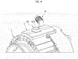
- FIG. 4 is a view showing a part of a tub according to the present embodiment
- FIG. 5 is a view showing a part of an interior of a cabinet according to the present embodiment.
- an induction module 8 may be provided at an outer circumferential surface of a tub 2 according to the present embodiment, particularly, on an upper outer circumferential surface.
- a communication part 30 for communicating the outside of the cabinet 1, that is, the outside of the clothing treatment apparatus and the inside of the tub 2, may be provided at the outer circumferential surface of the tub 2.
- the communication part 30 includes a cabinet communication part 33 connected to the cabinet 1, a tub communication part 31 connected to the inside of the tub 2, and a bellows part 32 connecting the cabinet communication part 33 and the tub communication part 31.
- the bellows part 32 As the bellows part 32 is provided, the outside of the cabinet 1 and the inside of the tub 2 may communicate stably even when the tub 2 vibrates.
- air in the tub 2 may be discharged to the outside of the cabinet 1 and air outside the cabinet 1 may be introduced into the tub 2.
- the gasket 4 may be stretchable and the communication part 30 may not be separated from the cabinet 1 or the tub 2 through the bellows part 32.
- the tub 2 can be moved to its original position by the tub support parts 131 and 132, specifically, the first support part 131 and the second support part 132, a stable operation may be possible.
- FIG. 6 is a block diagram of a clothing treatment apparatus according to the present embodiment.
- a controller 9 may be provided as a main processor to control the operation of the clothing treatment apparatus. The operation of various control elements to be described later may be controlled by the controller 9.
- the controller 9 may be provided in a control panel 5 and the like, and the controller 9 may receive a user's command for operating the clothing treatment apparatus through a manipulation part, which is provided in a control panel 5, so as to perform various washing operations and options described above.
- the controller 9 may include a module controller 86 capable of controlling the operation of an induction module 8.
- the module controller 86 may control whether or not the induction module 8 is being operated and an operation time of the induction module 8.
- a processor for controlling the induction module 8 and a processor for controlling other components of the clothing treatment apparatus may be provided separately.
- the processor for controlling the induction module 8 and the processor for controlling other components may be connected to communicate with each other. Therefore, it is possible to improve control efficiency and prevent overload of the processors.
- the controller 9 may control the water supply valve (not shown), the drain pump 141, and the driver 6 by using water level information detected by a sensor such as a water level sensor (not shown).
- the control panel 5 may include a display part, and may provide the user with various courses and a current state of the above-described clothing treatment apparatus.
- controller 9 may control a coolant supply valve 70a so that coolant can be added during drying. When the coolant is input, moisture may be effectively condensed.
- controller 9 may control the driving of a motor through the driver 6 to generate various drivings such as a tumbling driving, a filtration driving, and a spin driving of the drum 3.
- a driving state of the drum 3 may be referred to as an operation of the drum.
- the tumbling driving of the drum 3 may be a driving that causes clothes (laundry) inside the drum 3 to be lifted and then fall as the drum rotates at approximately 40 to 46 RPM. That is, the tumbling driving may be a driving in which washing or wetting is performed by a mechanical force due to the fall of the clothes and friction with the drum. Since it is a driving in which the clothes are agitated in the drum 3, the tumbling driving may be is a driving that is frequently used in general.
- the filtration driving of the drum 3 may be a driving in which as the drum 3 rotates at approximately 100 RPM, the clothes are rotated integrally with the drum while closely contacting an inner circumferential surface of the drum 3 in the drum 3. In this case, the laundry clothes are spread over the inner circumferential surface of the drum 3, and the washing water is separated from the clothes.
- the spin driving of the drum 3 may be a driving of centrifugal spin-drying of washing water from the clothes as the drum 3 rotates at about 800 RPM or more.
- the spin driving is performed by a very large centrifugal force in a final process of washing, so that all washing can be terminated.
- the clothing treatment apparatus may perform at least one of washing, rinsing, spin-drying, and drying cycles.
- FIG. 7 is a view showing a washing course according to the present embodiment.
- the clothing treatment apparatus of the present embodiment may be configured to perform a water supply/wetting cycle S10, a washing cycle S20, a spin-drying cycle S30, a rinsing cycle S40, and a spin-drying cycle S50 sequentially.
- the washing cycle may be a cycle in which a drum 3 is rotated according to a preset algorithm to remove contaminants from laundry, and in which a rolling motion and a tumbling motion may be performed.
- the spin-drying cycle is a cycle of removing water from clothes while rotating the drum 3 at a high speed.
- the rinsing cycle may be a cycle of removing detergent adhered to the clothes, the cycle in which water is supplied, a rolling motion and a tumbling motion is performed, and then a spin-drying cycle is performed again.
- Thee spin-drying cycle S50 may be performed after the rinsing cycle S40, and a drying cycle S60 may be performed upon completion of the spin-drying cycle S50.
- the drying cycle S60 may be a cycle of removing moisture contained in the clothes even when the spin-drying cycle S50 is performed.
- An RPM of the drum 3 in the drying cycle S60 may be set to be greater than an RPM of the drum 3 in the spin-drying cycle S50.
- the spin-drying cycle S50 may be performed as a filtration motion in which the drum 3 is rotated to an extent in which the clothes adhere to the inner circumferential surface of the drum 3.
- the RPM of the drum 3 may be set to be higher than that of the filtration motion.
- FIG. 8 8 is a view showing a drum RPM in a tub vibrating step according to the present embodiment
- FIG. 9 is a view showing a tub vibrating step according to the present embodiment
- FIG. 10 is a plane view showing an interior of a clothing treatment apparatus according to the present embodiment.
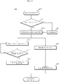
- FIG. 11 is an operation diagram of a clothing treatment apparatus according to the present embodiment.
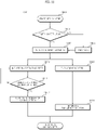
- a drying cycle of a clothing treatment apparatus may include at least one of an induction operating step S610 and a tub vibrating step S620.
- the induction operating step S610 may be a step of operating the above-described induction module 8. Air in the tub 2 may be heated in the induction operating step S610 to increase a water content.
- an operation of the induction module 8 may be performed by a controller 9, specifically, a module controller 86.
- the controller 9 may control an operating state of the induction module 8 according to an operating time of the induction module 8 or a state of clothes in the drum 3 in addition to an on/off state of the induction module.
- the induction module 8 may be turned on or off based on a value measured by at least one of the above-described temperature sensors 133a and 133b.
- the clothing treatment apparatus may receive a user's input through a control panel 5 or the like, and the controller 9 may control the induction module 8 based on the user's input.
- the controller 9 may control the induction module 8 and the driver 8 to perform at least one of the operation of the induction module 8 and the operation of vibrating the tub 2 by adjusting a rotational speed of the drum 3.
- the tub vibrating step S620 may mean that the tub 2 is controlled to vibrate in response to rotation of the drum 3.
- the tub 2 may vibrate back and forth in a longitudinal direction of the tub 2 in response to the rotation of the drum 3.
- the tub 2 may resonate at a specific rotational speed (RPM) of the drum 3.
- RPM rotational speed
- a rotational speed of the drum 3 at which the tub 2 resonates may vary.
- the size and mass of the drum 3 and the tub 2 may vary depending on various factors such as the size or use of the clothing treatment apparatus. Therefore, an RPM of the drum 3 for the tub 2 to resonate in response to the rotation of the drum 3 may vary according to circumstance.
- a clothing treatment apparatus it is possible to improve drying performance by causing each of air discharge and air introduction to be performed at least once in a section where the RPM of the drum 3 increases and/or decreases.
- the RPM of the drum 3 may be increased up to a target RPM at which there is at least one section where the tub 2 is able to resonate in response to rotation of the drum 3. Therefore, the tub 2 may resonate at least once or more.
- the tub 2 When resonance occurs, the tub 2 may vibrate in the front and rear directions of the cabinet 1, and accordingly, as the gasket expands and contracts, air in the cabinet 1 flows through the communication part 30 of the cabinet 1. Air discharged to the outside and outside the cabinet 1 may be introduced into the cabinet 1.
- the air in the tub 2 may be discharged to the outside of the cabinet 1 and the air outside the cabinet 1 may be introduced into the tub 2.
- the tub vibrating step S620 may include an RPM increasing step S621, an RPM maintaining step S623 and an RPM decreasing step S624.
- the RPM increasing step S621 may be a step in which the RPM is increased up to a target RPM at which there is at least one section where the tub 2 is able to resonate to correspond to a rotational RPM of the drum 3.
- the target RPM may be determined as a rotational speed greater than 300RPM.
- the vibration of the tub 2 does not stop immediately at a time when the rotational speed of the drum 3 deviates from the specific RPM.
- the first support part 131 and the second support part 132 included in the tub support parts 131 and 132 damp the vibration of the tub 2, but when the rotational speed of the drum 3 deviates from the specific RPM, the tub 2 does not stop vibrating immediately but instead may keep vibrating as an amplitude of the vibration decreases.
- the rotational speed of the drum 3 is out of an RPM where resonance occurs, the amplitude of the vibration decreases, but the tub 2 may continue vibrating and then gradually stop vibrating. Therefore, when resonance occurs, the discharge and introduction of air through the communication part 30 may be performed several times, respectively.
- the amplitude at which the tub 2 vibrates may change over time.
- the target RPM may be set to be greater than the rotational speed of the drum 3.
- the target RPM may be higher than an RPM of a filtration motion in which the clothes are rotated while closely contacting the inner circumferential surface of the drum 3.
- the target RPM may be set to be greater than the rotational speed of the drum 3 in the washing, spin-drying, and rinsing cycles so that the rotational speed of the drum 3 in which the tub 2 can resonate is included as much as possible.
- the target RPM may be set within a predetermined range based on the RPM capable of generating resonance.
- the target RPM may be 380 to 420 RPM. It may be effective if the target RPM is slightly greater than an RPM at which resonance can occur.
- the target RPM may be 400 RPM.
- the target RPM may be set so that the tub 2 can resonate in response to the rotation of the drum 3 without the entire clothing treatment apparatus resonating.
- the controller 9 may determine whether the target RPM is reached S622. When the target RPM is reached, under the control of the controller 9, the RPM increasing step S621 may be terminated and the RPM maintaining step may be performed. That is, when the RPM of the drum 3 reaches the target RPM, the drum 3 is driven at the target RPM for a predetermined time, and the RPM of the drum 3 may decrease after the predetermined time passes. Meanwhile, if the target RPM is not reached, the RPM increasing step S621 may be continuously performed.
- the RPM maintaining step S623 may be a step in which when the RPM of the drum 3 is increased to a preset target RPM through the RPM increasing step S621, the drum 3 is rotated at the target RPM without increasing the RPM of the drum 3 above the target RPM.
- the RPM maintaining step S623 may be performed for a time less than a time required for the RPM increasing step S621.
- the target RPM may not be the RPM at which the tub 2 resonates. Therefore, it is not necessarily required to maintain the RPM maintaining step S623 for a long time.
- the amplitude at which the tub 2 vibrates in the longitudinal direction of the tub 2 may gradually decrease, and thus, the drum 3 does not need to be driven at the target RPM for a long time.
- the RPM decreasing step S624 may be performed.
- the RPM decreasing step S624 may be a step in which the number of rotations of the drum 3 being rotated at the target RPM gradually decreases.
- the RPM of the drum 3 may decrease from the target RPM.
- a rotational speed (RPM) of the drum 3 at the end of the RPM decreasing step S624 may be a rotational speed (RPM) of the drum 3 at the start of the RPM increasing step S621.
- a specific RPM at which the tub 2 can resonate in response to rotation of the drum 3 may be included at least once or more.
- the tub 2 may resonate and vibrate back and forth in the longitudinal direction of the cabinet 1 or in the longitudinal direction of the tub 2.
- the RPM increasing step S621, the RPM maintaining step S623 and the RPM decreasing step S624 may be repeatedly performed multiple times. That is, the tub vibrating step S620 may be performed multiple times.
- the driver 6 may cause the drum 3 to sequentially and repeatedly perform revolutions so as to increase the RPM of the drum 3 to the target RPM, maintains the increased RPM, and decreases the increased RPM.
- the controller 9 may control so that an RPM increasing speed in the RPM increasing step S621 is smaller than an RPM decreasing speed in the RPM decreasing step S624. That is, an RPM increase rate in a section S621 in which the RPM of the drum 3 increases may be smaller than a RPM decrease rate in a section S624 in which the RPM of the drum 3 decreases.
- the RPM decreasing step S624 the RPM decreases to an RPM at which the drying cycle S60 starts, so if the RPM of the drum decreases faster than a rate at which the RPM increases in the RPM increasing step S621, it is possible to quickly enter the RPM increasing step S621 again.
- a rate at which the RPM of the drum decreases in the RPM decreasing step S624 is greater than a rate at which the RPM of the drum increases in the RPM increasing step S621.
- the tub 2 may vibrate in the front-rear direction with respect to the longitudinal direction of the tub 2.
- a volume of a space formed by the inlet port 12, the gasket 4, the tub inlet part 21, and the tub 2 of the cabinet 1 (hereinafter, the space is referred to as a tub internal space) may vary.
- the gasket 4 When the tub 2 is moved toward the front side of the cabinet 1, the gasket 4 may reduce in length in the longitudinal direction of the cabinet 1. As the volume of the tub internal space decreases, the pressure of the air in the tub internal space may increase.
- the air in the tub internal space may be discharged to the outside of the cabinet 1 through the communication part 30 when the pressure of the air in the tub internal space increases.
- the gasket 4 may increase in length in the longitudinal direction of the cabinet 1. That is, as the volume of the tub internal space increases, the pressure of the air in the tub internal space may decrease.
- the air in the tub internal space may be introduced into the cabinet 1 through the communication part 30 when the pressure of the air in the tub internal space decreases.
- the air in the tub internal space may enter and exit through the communication part 30. Since the tub vibrating step S620 can be performed in the drying cycle S60, the air in the tub internal space may absorb moisture contained in clothes to dry the clothes and the humid air may be discharged to the outside of the cabinet 1 due to vibration of the tub 2. In addition, dry air present outside the cabinet 1 may be introduced into the tub internal space through the communication part 30 to dry the clothes again.
- the controller 9 may determine whether the tub vibrating step is terminated in step S625.
- the tub vibrating step S620 may vary according to a user's selection or may be determined depending on various factors such as a degree of drying of clothes.
- the tub vibrating step S620 may be terminated in step S626.
- the drying cycle S60 may be performed in the clothing treatment apparatus according to the present embodiment.
- whether there is no remaining water in the tub 2 may be determined in step S602.
- a laundry quantity of an object to be dried may be detected in step S603 after drainage in step S604.
- the induction operating step S610 and the tub vibrating step S620 may start together in the drying cycle S60.
- dry air in external air may flow into the cabinet at an early stage of drying to remove moisture from the clothes and then may be discharged to the outside of the cabinet 1.
- the controller 9 may operate the coolant supply valve 70a to add coolant into the tub 2.
- the controller 9 may open or close the coolant water supply valve 70a and adjust an amount of coolant to add.
- the controller 9 may control opening and closing of the coolant supply valve 70a to thereby effectively perform drying.
- the tub vibrating step S620 may also be terminated.
- the induction operation and the tub vibrating step S620 do not necessarily have to be stopped at the same time. That is, the induction operation and the tub vibrating step S620 may be stopped at the same time, but it is not always necessary to control the induction operation and the tub vibrating step S620 to be stopped at the same time.
- the drum 3 may still be at a hot temperature. If the tub vibrating step S620 is further performed for a predetermined time even after the induction operating step S610 is terminated in step S612, the temperature inside the clothing treatment apparatus may be lowered so as to quickly ensure a user's safety.
- the tub vibrating step S620 may improve the drying quality that is insufficient in the induction operating step S610 alone. Therefore, it is preferable that the tub vibrating step S620 be performed even after the induction operating step S610 is terminated.
- the controller 9 may control the coolant supply valve 70a to be continuously opened.
- the induction operating step S610 it is necessary to cool the internal space of the cabinet 1.
- energy may not be wasted unnecessarily because the induction operating step S610 is terminated.
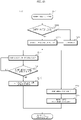
- FIG. 12 is a view showing a drying cycle of a clothing treatment apparatus according to another exemplary embodiment.
- the tub vibrating step S620 may start when a predetermined time passes after the start of the induction operating step S610.
- the tub vibrating step S620 may be a step of controlling a rotation RPM of the drum 3 to resonate the tub 2 in the front-rear direction of the cabinet 1, and in the tub vibrating step S620, air in an tub internal space may be discharged to the outside of the cabinet 1 and air outside the cabinet 1 may be introduced into the tub internal space.
- the tub internal space may be sufficiently heated only after a predetermined time passes. Therefore, performing the tub vibrating step S620 when a predetermined time passes after the start of the induction operating step S610 may be advantageous in terms of energy efficiency.
- a timing at which the tub vibrating step S620 starts may be determined according to temperature of the drum 3 or may be determined according to a predetermined time from a start time of the induction operating step S610.
- the tub vibrating step S620 may start in response to a user's arbitrary input.
- FIG. 13 is a view showing a drying cycle of a clothing treatment apparatus according to another embodiment.
- the tub vibrating step S620 may be performed after the induction operation S612 is terminated in S612. As described above, if the tub vibrating step S620 is performed after the induction operating step S610 is terminated, it may take a long time for drying.
- the air in the tub internal space may be heated and the air may be discharged to the outside of the cabinet 1.
- air since an inlet port 12 of the cabinet 1 is not completely sealed to an extent that air cannot be introduced, air may be introduced through the inlet port 12 of the cabinet 1 when the air in the tub internal space is discharged to the outside of the cabinet 1.
- the air may continuously circulate while the induction operating step S610 is performed.
- the tub vibrating step S620 may be performed.
- the tub vibrating step S620 is not performed while the induction operating step S610 is performed, the tub internal space is not cooled, so that a drying condition can be quickly met. Therefore, even if the tub vibrating step S620 is performed after the induction operating step S610, it may not take an excessively long drying time.
- the tub vibrating step S620 and the induction operating step S610 may be controlled independently of each other.
- the fact that the tub vibrating step S620 and the induction operating step S610 are allowed to be performed independently of each other does not mean that the tub vibrating step S620 and the induction operating step S610 are performed without affecting each other.
- the tub vibrating step S620 may be performed simultaneously with the induction operating step S610 or may be performed after the induction operating step starts. Furthermore, the tub vibrating step S620 may be performed during the induction operating step S610 or may be performed after the induction operating step S610 is terminated.
- the driver 6 may rotate the drum 3 so that an RPM of the drum 3 is increased to a target RPM after an operation of the induction module 8 is terminated, or the driver 6 may rotate the drum 3 so that an RPM of the drum 3 is increased to the target RPM when the induction module 8 is not operated.
- a coolant supply valve 70a for adding coolant into the tub 2 when opened may be further included, and the coolant supply valve 70a may remain open for a predetermined period of time even after the operation of the induction module 8 is terminated.
Landscapes
- Engineering & Computer Science (AREA)
- Textile Engineering (AREA)
- Physics & Mathematics (AREA)
- Electromagnetism (AREA)
- Detail Structures Of Washing Machines And Dryers (AREA)
- Control Of Washing Machine And Dryer (AREA)
Applications Claiming Priority (2)
| Application Number | Priority Date | Filing Date | Title |
|---|---|---|---|
| KR20200033143 | 2020-03-18 | ||
| PCT/KR2021/003365 WO2021187915A1 (ko) | 2020-03-18 | 2021-03-18 | 의류처리장치 |
Publications (2)
| Publication Number | Publication Date |
|---|---|
| EP4123085A1 true EP4123085A1 (de) | 2023-01-25 |
| EP4123085A4 EP4123085A4 (de) | 2024-05-01 |
Family
ID=77923323
Family Applications (1)
| Application Number | Title | Priority Date | Filing Date |
|---|---|---|---|
| EP21771427.8A Pending EP4123085A4 (de) | 2020-03-18 | 2021-03-18 | Vorrichtung zur behandlung von kleidung |
Country Status (2)
| Country | Link |
|---|---|
| EP (1) | EP4123085A4 (de) |
| KR (1) | KR102918223B1 (de) |
Families Citing this family (1)
| Publication number | Priority date | Publication date | Assignee | Title |
|---|---|---|---|---|
| WO2025135868A1 (ko) * | 2023-12-22 | 2025-06-26 | 엘지전자 주식회사 | 의류처리장치 |
Family Cites Families (8)
| Publication number | Priority date | Publication date | Assignee | Title |
|---|---|---|---|---|
| JP3536566B2 (ja) * | 1997-01-24 | 2004-06-14 | 松下電器産業株式会社 | 洗濯機 |
| JP4935764B2 (ja) * | 2008-06-11 | 2012-05-23 | パナソニック株式会社 | ドラム式洗濯機 |
| CN105899625B (zh) | 2014-01-10 | 2018-09-18 | 惠普发展公司,有限责任合伙企业 | 品红色墨水 |
| JP6400339B2 (ja) | 2014-06-05 | 2018-10-03 | 東芝ライフスタイル株式会社 | 衣類乾燥機 |
| JP6576213B2 (ja) | 2015-07-29 | 2019-09-18 | 東芝ライフスタイル株式会社 | 洗濯乾燥機 |
| KR20180023277A (ko) * | 2016-08-25 | 2018-03-07 | 엘지전자 주식회사 | 의류처리장치 |
| KR102325965B1 (ko) * | 2017-03-27 | 2021-11-11 | 엘지전자 주식회사 | 세탁물 처리기기의 탈수행정 제어방법 |
| KR102377042B1 (ko) * | 2017-08-09 | 2022-03-22 | 엘지전자 주식회사 | 의류처리장치 |
-
2021
- 2021-03-18 KR KR1020210035306A patent/KR102918223B1/ko active Active
- 2021-03-18 EP EP21771427.8A patent/EP4123085A4/de active Pending
Also Published As
| Publication number | Publication date |
|---|---|
| KR20210117215A (ko) | 2021-09-28 |
| EP4123085A4 (de) | 2024-05-01 |
| KR102918223B1 (ko) | 2026-01-27 |
Similar Documents
| Publication | Publication Date | Title |
|---|---|---|
| JP3605067B2 (ja) | ドラム式洗濯乾燥機 | |
| EP2630289B1 (de) | Waschmaschine und steuerungsverfahren dafür | |
| EP2581483B1 (de) | Wäschebehandlungsvorrichtung und Verfahren zu ihrer Ansteuerung | |
| US11542648B2 (en) | Laundry treating apparatus having induction heater and control method thereof | |
| EP3674471B1 (de) | Waschmaschine mit induktionsheizung | |
| US20060137105A1 (en) | Drying control apparatus and method of washing and drying machine | |
| US20180245267A1 (en) | Laundry treatment apparatus and method of controlling the same | |
| EP2623659B1 (de) | Steuerverfahren für eine Waschmaschine | |
| EP3674470B1 (de) | Waschmaschine mit induktionsheizung und steuerungsverfahren dafür | |
| US11530509B2 (en) | Laundry treating apparatus having induction heater and control method thereof | |
| US11479905B2 (en) | Laundry treating apparatus having induction heater and control method thereof | |
| EP4123085A1 (de) | Vorrichtung zur behandlung von kleidung | |
| JP2021171437A (ja) | ドラム式洗濯機 | |
| JP6716675B2 (ja) | 洗濯乾燥機 | |
| KR20210122021A (ko) | 의류처리장치 및 의류처리장치의 제어방법 | |
| CN102021784A (zh) | 滚筒式洗涤干燥机 | |
| EP4130375A1 (de) | Vorrichtung zur behandlung von kleidung | |
| EP3674467B1 (de) | Steuerungsverfahren für eine waschmaschine mit induktionsheizung | |
| JPH10295978A (ja) | ドラム式洗濯機 | |
| JP2002159777A (ja) | 洗濯乾燥機 | |
| US12473683B2 (en) | Clothing treatment apparatus | |
| JP2008284188A (ja) | 洗濯乾燥機 | |
| KR102895273B1 (ko) | 의류처리장치의 제어방법 | |
| JP4003600B2 (ja) | 洗濯乾燥機 | |
| US12497722B2 (en) | Clothing treatment apparatus |
Legal Events
| Date | Code | Title | Description |
|---|---|---|---|
| STAA | Information on the status of an ep patent application or granted ep patent |
Free format text: STATUS: THE INTERNATIONAL PUBLICATION HAS BEEN MADE |
|
| PUAI | Public reference made under article 153(3) epc to a published international application that has entered the european phase |
Free format text: ORIGINAL CODE: 0009012 |
|
| STAA | Information on the status of an ep patent application or granted ep patent |
Free format text: STATUS: REQUEST FOR EXAMINATION WAS MADE |
|
| 17P | Request for examination filed |
Effective date: 20221017 |
|
| AK | Designated contracting states |
Kind code of ref document: A1 Designated state(s): AL AT BE BG CH CY CZ DE DK EE ES FI FR GB GR HR HU IE IS IT LI LT LU LV MC MK MT NL NO PL PT RO RS SE SI SK SM TR |
|
| DAV | Request for validation of the european patent (deleted) | ||
| DAX | Request for extension of the european patent (deleted) | ||
| A4 | Supplementary search report drawn up and despatched |
Effective date: 20240402 |
|
| RIC1 | Information provided on ipc code assigned before grant |
Ipc: D06F 25/00 20060101ALN20240325BHEP Ipc: D06F 105/46 20200101ALN20240325BHEP Ipc: D06F 105/14 20200101ALN20240325BHEP Ipc: D06F 103/38 20200101ALN20240325BHEP Ipc: D06F 103/18 20200101ALN20240325BHEP Ipc: D06F 103/04 20200101ALN20240325BHEP Ipc: D06F 58/26 20060101ALN20240325BHEP Ipc: D06F 39/04 20060101ALN20240325BHEP Ipc: D06F 34/26 20200101ALN20240325BHEP Ipc: D06F 33/64 20200101ALN20240325BHEP Ipc: H05B 6/42 20060101ALI20240325BHEP Ipc: D06F 33/63 20200101ALI20240325BHEP Ipc: H05B 6/10 20060101ALI20240325BHEP Ipc: D06F 34/10 20200101ALI20240325BHEP Ipc: D06F 58/38 20200101AFI20240325BHEP |