EP4123100B1 - Dachkonstruktion - Google Patents
Dachkonstruktion Download PDFInfo
- Publication number
- EP4123100B1 EP4123100B1 EP22185481.3A EP22185481A EP4123100B1 EP 4123100 B1 EP4123100 B1 EP 4123100B1 EP 22185481 A EP22185481 A EP 22185481A EP 4123100 B1 EP4123100 B1 EP 4123100B1
- Authority
- EP
- European Patent Office
- Prior art keywords
- channel
- water
- roof construction
- construction according
- rafter
- Prior art date
- Legal status (The legal status is an assumption and is not a legal conclusion. Google has not performed a legal analysis and makes no representation as to the accuracy of the status listed.)
- Active
Links
Images


Classifications
-
- E—FIXED CONSTRUCTIONS
- E04—BUILDING
- E04D—ROOF COVERINGS; SKY-LIGHTS; GUTTERS; ROOF-WORKING TOOLS
- E04D3/00—Roof covering by making use of flat or curved slabs or stiff sheets
- E04D3/02—Roof covering by making use of flat or curved slabs or stiff sheets of plane slabs, slates, or sheets, or in which the cross-section is unimportant
- E04D3/06—Roof covering by making use of flat or curved slabs or stiff sheets of plane slabs, slates, or sheets, or in which the cross-section is unimportant of glass or other translucent material; Fixing means therefor
- E04D3/08—Roof covering by making use of flat or curved slabs or stiff sheets of plane slabs, slates, or sheets, or in which the cross-section is unimportant of glass or other translucent material; Fixing means therefor with metal glazing bars
-
- E—FIXED CONSTRUCTIONS
- E04—BUILDING
- E04D—ROOF COVERINGS; SKY-LIGHTS; GUTTERS; ROOF-WORKING TOOLS
- E04D13/00—Special arrangements or devices in connection with roof coverings; Protection against birds; Roof drainage ; Sky-lights
- E04D13/04—Roof drainage; Drainage fittings in flat roofs, balconies or the like
- E04D13/08—Down pipes; Special clamping means therefor
-
- E—FIXED CONSTRUCTIONS
- E04—BUILDING
- E04D—ROOF COVERINGS; SKY-LIGHTS; GUTTERS; ROOF-WORKING TOOLS
- E04D3/00—Roof covering by making use of flat or curved slabs or stiff sheets
- E04D3/02—Roof covering by making use of flat or curved slabs or stiff sheets of plane slabs, slates, or sheets, or in which the cross-section is unimportant
- E04D3/06—Roof covering by making use of flat or curved slabs or stiff sheets of plane slabs, slates, or sheets, or in which the cross-section is unimportant of glass or other translucent material; Fixing means therefor
- E04D3/08—Roof covering by making use of flat or curved slabs or stiff sheets of plane slabs, slates, or sheets, or in which the cross-section is unimportant of glass or other translucent material; Fixing means therefor with metal glazing bars
- E04D2003/0893—Glazing bars comprising means for draining condensation water or infiltrated rainwater
-
- E—FIXED CONSTRUCTIONS
- E04—BUILDING
- E04D—ROOF COVERINGS; SKY-LIGHTS; GUTTERS; ROOF-WORKING TOOLS
- E04D13/00—Special arrangements or devices in connection with roof coverings; Protection against birds; Roof drainage ; Sky-lights
- E04D13/04—Roof drainage; Drainage fittings in flat roofs, balconies or the like
- E04D13/0404—Drainage on the roof surface
- E04D13/0445—Drainage channels
- E04D2013/045—Drainage channels on inclined roofs
-
- E—FIXED CONSTRUCTIONS
- E04—BUILDING
- E04D—ROOF COVERINGS; SKY-LIGHTS; GUTTERS; ROOF-WORKING TOOLS
- E04D13/00—Special arrangements or devices in connection with roof coverings; Protection against birds; Roof drainage ; Sky-lights
- E04D13/04—Roof drainage; Drainage fittings in flat roofs, balconies or the like
- E04D13/08—Down pipes; Special clamping means therefor
- E04D2013/0893—Down pipes; Special clamping means therefor incorporated in building structure
Definitions
- the invention relates to a roof construction with a supporting frame, which is supported by a supporting structure and has at least two longitudinal beams arranged parallel to one another and at a distance from one another and at least two transverse beams arranged parallel to one another and at a distance from one another and which surrounds a frame field, and with at least one rafter, which connects the transverse beams to one another, runs at a distance from the longitudinal beams and divides the frame field into several roof fields, wherein at least one of the roof fields is covered by a cover plate and wherein a water channel is formed in or on the rafter, which runs in the longitudinal direction of the rafter and opens into a collecting channel via a water outlet in its axial end region.
- the document DE 3637715 A1 reveals such a roof construction.
- a roof structure of this type can be, for example, the roof of a winter garden, a building extension, or a pavilion.
- the preferably flat supporting frame can be rectangular and consist of two parallel and spaced-apart longitudinal beams and two parallel and spaced-apart cross members.
- a supporting structure which consists of columns and/or building parts or other supporting elements to which the supporting frame is attached and via which the loads of the supporting frame can be safely transferred.
- a frame section is formed, enclosed by the longitudinal beams and the cross beams, which is divided into several roof sections by at least one rafter that connects the cross beams.
- At least one roof section, and preferably all roof sections are each covered by a flat cover plate, in particular made of glass, wood, metal, or plastic, so that objects or people standing below the supporting frame are protected from rain.
- a cover plate in particular made of glass, wood, metal, or plastic, so that objects or people standing below the supporting frame are protected from rain.
- the cover plates it is known to arrange the cover plates at an angle relative to a horizontal plane so that the water can drain off the upper side of the cover plates.
- a water channel can be formed in the rafter, into which the water on the upper side of the cover plate flows and is collected.
- a gutter On the end face of the rafter that is at a lower height, a gutter is arranged, into which the water can flow from the water channel of the rafter.
- the water flows along the gutter to a vertical downpipe, which carries the water away from the roof structure and either discharges it into a further sewer system or releases it into the environment.
- Both the gutter which in many cases is located at one of the Both the cross beam and the vertical downpipe significantly impair the aesthetics of the roof structure and also require excessive construction and installation effort.
- the gutter is designed as a free-surface gutter that is open at the top, there is a risk that it will become dirty and blocked after prolonged use, so that further structural measures are necessary to either clean the gutter or prevent foreign objects from entering.
- the invention is based on the object of creating a roof construction of the type mentioned, in which the water on the cover plates can be reliably drained away in a structurally simple manner.
- the roof structure according to the invention also provides a preferably flat and slightly inclined or horizontally oriented support frame, which is directly or indirectly supported on the ground by means of a supporting structure, for example, vertical supports and/or building components.
- the support frame is preferably rectangular and has at least two longitudinal beams arranged parallel to one another at a distance from one another and at least two transverse beams arranged parallel to one another at a distance from one another.
- the longitudinal beams and the transverse beams surround a so-called frame field located inside the support frame.
- At least one rafter is provided, which runs at a distance from the longitudinal beams, preferably parallel to them, and connects the cross beams to one another.
- several rafters are arranged parallel to one another at a distance.
- the rafter(s) divide the frame field into several roof fields. At least some of the roof fields, and preferably all of the roof fields, are each covered by a preferably flat cover plate, in particular made of glass, which runs inclined relative to a horizontal such that water that collects on the upper side of the cover plates, for example as a result of rain, runs towards the rafter assigned to the respective cover plate.
- a water channel can be formed in or on the rafter, which runs in the longitudinal direction of the rafter.
- the water channel is integrated into the rafter, i.e., arranged inside the rafter.
- the rafter runs either horizontally or at an incline relative to the horizontal, so that the water flows along the water channel of the rafter.
- a water outlet is provided, at which the water channel opens into a collecting channel.
- the collecting duct is formed, at least in sections, by a pipe or a hose, and in particular by a corrugated pipe or a corrugated hose.
- a hose is a closed duct that is easily deformable, allowing it to be easily adapted to the structural conditions. The hose can run at different heights and can be easily guided around obstacles in the path.
- a pipe is also a closed duct and, compared to a hose, has greater flexural stability and is preferably designed to be inherently stable.
- the collecting channel can be formed by a single, continuous pipe or hose. Alternatively, it is possible to assemble the collecting channel from several pipe and/or hose sections, with adjacent pipe and/or hose sections each connected to each other via a preferably tubular connector and/or connected to the water outlet of the rafter's water channel.
- the collecting channel can run horizontally or at an angle of inclination of 0.1° to 5° and preferably in the range of ⁇ 1° to 3° to the horizontal.
- the collecting duct runs along one of the cross members and is arranged in particular within the cross member, so that on the one hand it is protected from external weather influences and on the other hand it does not affect the aesthetic appearance of the roof construction.
- the tubular connector which can be T-shaped or L-shaped, for example, has several connections, one of which is connected to the water outlet of the water channel.
- the other connection(s) of the connector are each connected to one of the hose sections that form the collecting channel.
- rafters have an internal water channel, it is preferably provided that the water channels of several rafters and in particular all rafters open into the collecting channel.
- a roof structure of the type mentioned is often attached to a building or located near a building.
- the collecting duct runs on or in the cross member facing away from the building.
- the water supplied to the collecting channel must be drained away.
- the collecting channel can be connected to or discharged into a further first drainage channel via at least one preferably tubular first outlet piece.
- the first drainage channel can also be formed, at least in sections and preferably entirely, by a pipe or hose, in particular a corrugated pipe or hose.
- the first discharge channel runs horizontally or at an angle of 0.1° to 5° and preferably in the range of ⁇ 1° to 3° inclined to the horizontal.
- the first discharge channel can run parallel to the collecting channel. Furthermore, the first discharge channel can run within one of the cross members, particularly within the cross member in which the collecting channel is also located.
- the water arranged on top of the cover plates flows into the water channels of the rafters in the manner mentioned and then flows in the water channels to the respective water outlet and through this into the collecting channel.
- the water in the collecting channel flows through the first outlet into the continuing first drainage channel and is drained away therein.
- the first drainage channel opens at its downstream end via a preferably tubular second outlet into a continuing second drainage channel.
- the second drainage channel can be formed at least in sections and preferably entirely by a pipe or a hose and in particular a corrugated pipe or corrugated hose.
- a collection tank and/or an overflow is provided in the area of the transition from the first drainage channel to the second drainage channel, and in particular in the second outlet located there. If the amount of water to be drained is below a predetermined limit, the water flows completely from the first drainage channel through the second outlet into the second drainage channel. If the amount of water to be drained is relatively large for a short time, it can be collected and temporarily stored in the collection tank. and then, over time, flows from the collection tank through the second drainage channel. If the amount of water to be drained is too large over an extended period of time and/or the second drainage channel is blocked or can no longer hold water, the water escapes at the overflow and flows downwards to the ground outside the second drainage channel due to gravity.
- an overflow channel is provided, which is arranged at the axial end of the rafter water channels opposite the water outlet. If drainage of water from the water channel of one rafter or all rafters is no longer possible, for example because the collecting channel is overloaded or blocked and/or the first drainage channel is overloaded or blocked, the water collects in the rafter water channels. When a predetermined water level is reached within the rafter water channels, the additional water flows into the overflow channel at the end of the rafter water channel opposite the water outlet, preferably at a higher level, and is drained through it.
- the overflow channel preferably has the same structural design as the collecting channel, i.e., it is connected to the rafter water channels via preferably tubular connecting pieces, with pipe or hose sections running between the connecting pieces.
- the overflow channel runs in or on the other cross member and preferably merges into one of the longitudinal members at the end of the cross member.
- the overflow channel can either drain the water independently of the second drainage channel or flow into the second drainage channel.
- the overflow channel can be connected to the second outlet piece, for example.
- a filter device is arranged in the flow path of the water from the upper side of the cover plate to the water channel of the associated rafter, through which the water flows. In this way, foreign bodies are prevented from entering the water channel of the rafter and clogging it.
- the filter device is preferably provided in the form of a strip-shaped bristle seal, for example, which is formed by an elongated arrangement of bristles and/or bristle bundles and can be attached to the rafter above the cover plate in such a way that the ends of the bristles and/or bristle bundles rest on the upper side of the cover plate from above.
- the filter device additionally serves as a hold-down device that clamps the cover plate against the first bearing surface of the rafter.
- the longitudinal beams 12 and the cross beams 13 surround a frame field 11a located inside the supporting frame 11, which is divided into several roof fields 20 by means of several rafters 15.
- four rafters 15 are present, which divide the frame field 11a into five preferably approximately equal-sized, rectangular roof fields 20.
- the roof fields 20 are each completely covered by a flat cover plate 16, which can be made of glass.
- Each cover plate 16 has a long longitudinal axis L L and a short longitudinal axis L K running perpendicular thereto, wherein the cover plates 16 are at least the long longitudinal axis L L is arranged inclined relative to a horizontal.
- Adjacent cover plates 16 are each mounted with one end on one of the rafters 15, as is particularly the case in Fig. 2 is shown.
- the rafter 15 has a first support surface 26 in a side wall 15a, on which an edge region of one of the cover plates 16 is supported.
- a chamber-like recess 29 is formed in the rafter 15, on the bottom of which a second support surface 27 is formed.
- An adjacent further cover plate 16 is inserted with its edge region into the recess 29 and supported on the second support surface 27.
- a filter device 31 is provided through which the water flows before the water enters the water channel 18. This prevents foreign matter from entering the water channel 18. and can clog it.
- a strip-shaped bristle seal 32 is provided as the filter device 31. This strip-shaped bristle seal is formed by an elongated arrangement of bristles and/or bristle bundles and is attached to the rafter 15 above the cover plate 16 in such a way that the ends of the bristles and/or bristle bundles rest on the upper side of the cover plate 16.
- the filter device 31 or the bristle seal 32 also serves as a hold-down device that clamps the cover plate 16 against the first support surface 26.
- the water outlet 28 is arranged at the lower axial end of the water channel 18 facing away from the building wall 30, into which a T-shaped connecting piece 33 with a connection 35 is inserted (see Fig. 4 ).
- the connecting piece 33 has further connections 36 and 37, onto each of which a hose section 34 of a flexible corrugated hose or a pipe section is placed.
- the pipe or hose sections 34, together with the connecting pieces 33, form a collecting channel 21, which receives the water flowing out of the water channels 18.
- the collecting channel 21 runs essentially perpendicular to the rafters 15 and in particular within the Fig. 1 front or lower cross member 13 facing away from the building wall 30.
- a further water outlet 42 is provided, which is located at a higher level than the water outlet 28.
- the further water outlet 42 opens via a further connecting piece 43 into an overflow channel 41, which can have the same structural design as the collecting channel 21, i.e. it can be connected to the individual water channels of the rafters via additional tubular connecting pieces, with pipe or hose sections running between the additional connecting pieces.
- the first discharge channel 23 is connected to a second outlet 39, as shown in Fig. 4 and especially in Fig. 5 is shown.
- the second outlet piece 39 has an upwardly open collecting tank 44, which has an upper outlet 40 serving as an overflow and into which the first drainage channel 23 opens via a first upper connection 39a.
- a lower connection 39c is connected to a continuing second drainage channel 24, which extends essentially vertically and is formed by a pipe or a hose, in particular in the form of a corrugated hose.
- the second drainage channel 24 runs within the support 17 and is connected at its lower end either to a continuing line or a sewer system in a manner not shown, or opens into the surrounding area.
- the overflow channel 41 runs in or on the cross member 13 facing the building wall.
- the overflow channel 41 can drain the water either independently of the vertical 2nd drainage channel 24 or alternatively in the vertical 2nd
- the overflow channel 41 runs through the longitudinal member 12 to the second mouth piece 39 and opens there into the collecting tank 44 via a second upper connection 39b.
- the water collecting on the cover plates 16 of the roof structure 10 flows in the aforementioned manner into the water channels 18 of the rafters 15 and flows therein to the respective water outlet 28 and through the connecting pieces arranged therein into the collecting channel 21. From the collecting channel 21, the water flows via the 1st outlet piece 38 into the 1st drainage channel 23 to the 2nd outlet piece 39 and from there into the 2nd drainage channel 24.
- the water is first collected in the collection tank 44. If this is completely full, excess water exits at the outlet 40, as indicated by the arrow W 2 in Fig. 4 is indicated.
- the collecting channel 21 and/or the 1st drainage channel 23 should be blocked, the water cannot drain sufficiently from the water channels 18 of the rafters 15, so that the water level in the water channels 18 of the rafters 15 rises until the water has reached a predetermined height so that it can drain through the further water outlet 42 of the rafters 18 and the overflow channel 41 and flow to the 2nd mouth piece 39, where it flows through the collecting tank 44 and is discharged through the 2nd drainage channel 24.
Landscapes
- Engineering & Computer Science (AREA)
- Architecture (AREA)
- Civil Engineering (AREA)
- Structural Engineering (AREA)
- Roof Covering Using Slabs Or Stiff Sheets (AREA)
Description
- Die Erfindung betrifft eine Dachkonstruktion mit einem Tragrahmen, der mittels einer Tragkonstruktion abgestützt ist und zumindest zwei parallel zueinander und in gegenseitigem Abstand angeordnete Längsträger und zumindest zwei parallel zueinander und in gegenseitigem Abstand angeordnete Querträger aufweist und der ein Rahmenfeld umgibt, und mit zumindest einem Sparren, der die Querträger miteinander verbindet, im Abstand zu den Längsträgern verläuft und das Rahmenfeld in mehrere Dachfelder unterteilt, wobei zumindest eines der Dachfelder mittels einer Abdeckplatte abgedeckt ist und wobei in oder an dem Sparren ein Wasserkanal ausgebildet ist, der in Längsrichtung des Sparrens verläuft und der in seinem axialen Endbereich über einen Wasserauslass in einem Sammelkanal mündet. Das Dokument
DE 3637715 A1 offenbart eine solche Dachkonstruktion. - Bei einer Dachkonstruktion der genannten Art kann es sich beispielsweise um das Dach eines Wintergartens, eines Gebäude-Anbaus oder eines Pavillons handeln. Der vorzugsweise ebene Tragrahmen kann rechteckig ausgebildet und aus zwei parallel zueinander verlaufenden und voneinander beabstandeten Längsträgern sowie zwei parallel zueinander verlaufenden und voneinander beabstandeten Querträgern aufgebaut sein.
- Um den Tragrahmen abzustützen, ist eine Tragkonstruktion vorgesehen, bei der es sich um Stützen und/oder Gebäudeteile oder sonstige Tragelemente handelt, an denen der Tragrahmen befestigt ist und über die die Lasten des Tragrahmens sicher abgeleitet werden können.
- Im Inneren des Tragrahmens ist ein von den Längsträgern und den Querträgern eingefasstes Rahmenfeld gebildet, das mittels zumindest eines Sparrens, der die Querträger miteinander verbindet, in mehrere Dachfelder unterteilt ist. Zumindest ein Dachfeld und vorzugsweise alle Dachfelder sind jeweils mittels einer ebenen Abdeckplatte insbesondere aus Glas, Holz, Metall oder Kunststoff abgedeckt, so dass Gegenstände oder Personen, die unterhalb des Tragrahmens stehen, vor Regen geschützt sind. Wenn es regnet, fällt der Regen von oben auf die Abdeckplatten und muss von diesen abgeleitet werden. Zu diesem Zweck ist es bekannt, die Abdeckplatten geneigt relativ zu einer Horizontalen anzuordnen, so dass das Wasser auf der Oberseite der Abdeckplatten abfließen kann. Zu diesem Zweck kann in dem Sparren ein Wasserkanal ausgebildet sein, in den das auf der Oberseite der Abdeckplatte befindliche Wasser einströmt und aufgefangen wird. An derjenigen Stirnseite des Sparrens, die auf einem geringeren Höheniveau liegt, ist eine Regenrinne angeordnet, in die das Wasser aus dem Wasserkanal des Sparrens einströmen kann. Das Wasser strömt entlang der Regenrinne zu einem vertikalen Fallrohr, das das Wasser von der Dachkonstruktion wegführt und entweder in eine weiterführende Kanalisation einleitet oder an die Umwelt abgibt. Sowohl die Regenrinne, die in vielen Fällen an einem der Querträger angebracht ist, als auch das vertikale Fallrohr beeinträchtigen die Ästhetik der Dachkonstruktion wesentlich und erfordern zusätzlich einen übermäßigen Konstruktions- und Montageaufwand.
- Da die Regenrinne als nach oben offene Freispiegelrinne ausgestaltet ist, besteht die Gefahr, dass diese bei längerem Gebrauch verschmutzt und verstopft, so dass weitere konstruktive Maßnahmen notwendig sind, um entweder die Regenrinne zu reinigen oder ein Eintreten von Fremdkörpern zu verhindern.
- Der Erfindung liegt die Aufgabe zugrunde, eine Dachkonstruktion der genannten Art zu schaffen, bei der das auf den Abdeckplatten befindliche Wasser in konstruktiv einfacher Weise zuverlässig abgeleitet werden kann.
- Diese Aufgabe wird erfindungsgemäß durch eine Dachkonstruktion mit den Merkmalen des Anspruchs 1 gelöst.
- Auch bei der erfindungsgemäßen Dachkonstruktion ist ein vorzugsweise ebener und leicht geneigt oder horizontal ausgerichteter Tragrahmen vorgesehen, der mittels einer Tragkonstruktion, beispielsweise vertikalen Stützen und/oder Gebäudeteilen am Erdboden mittelbar oder unmittelbar abgestützt ist. Der Tragrahmen ist vorzugsweise rechteckig ausgebildet und besitzt zumindest zwei parallel zueinander in gegenseitigem Abstand angeordnete Längsträger und zumindest zwei parallel zueinander in gegenseitigem Abstand angeordnete Querträger. Die Längsträger und die Querträger umgeben ein sogenanntes Rahmenfeld, das im Inneren des Tragrahmens liegt.
- Es ist zumindest ein Sparren vorgesehen, der im Abstand zu den Längsträgern vorzugsweise parallel zu diesen verläuft und die Querträger miteinander verbindet. Vorzugsweise sind mehrere Sparren auf Abstand parallel nebeneinander angeordnet. Der oder die Sparren unterteilen das Rahmenfeld in mehrere Dachfelder. Zumindest einige der Dachfelder und vorzugsweise alle Dachfelder sind jeweils mittels einer vorzugsweise ebenen Abdeckplatte insbesondere aus Glas abgedeckt, die geneigt relativ zu einer Horizontalen so verläuft, dass Wasser, das sich beispielsweise in Folge von Regen auf der Oberseite der Abdeckplatten ansammelt, in Richtung des der jeweiligen Abdeckplatte zugeordneten Sparrens abläuft. In oder an dem Sparren kann ein Wasserkanal ausgebildet sein, der in Längsrichtung des Sparrens verläuft. Vorzugsweise ist der Wasserkanal in den Sparren integriert, d.h. im Inneren des Sparrens angeordnet. Der Sparren verläuft entweder horizontal oder unter einer Neigung gegenüber der Horizontalen, so dass das Wasser in dem Wasserkanal des Sparrens entlang strömt. In einem axialen Endbereich des Sparrens ist ein Wasserauslass vorgesehen, an dem der Wasserkanal in einem Sammelkanal mündet. Der Sammelkanal ist zumindest abschnittsweise von einem Rohr oder einem Schlauch und insbesondere von einem Wellrohr oder einem Wellschlauch gebildet. Ein Schlauch ist ein geschlossener Kanal, der leicht verformbar ist, so dass der Schlauch in einfacher Weise an die baulichen Gegebenheiten angepasst werden kann. Der Schlauch kann über verschiedene Höhenebenen verlaufen und um im Weg liegende Hindernisse in einfacher Weise herumgeführt werden. Ein Rohr ist ebenfalls ein geschlossener Kanal und weist im Vergleich zum Schlauch eine höhere Biegestabilität auf und ist vorzugsweise eigenstabil ausgestaltet.
- Die Dichtheit des vom Rohr oder Schlauch gebildeten Kanals ist in einfacher Weise gewährleistet. Darüber hinaus ist bei einem Rohr oder Schlauch zuverlässig verhindert, dass von außen Fremdkörper oder Verschmutzungen eingetragen werden.
- Der Sammelkanal kann von einem einheitlichen kontinuierlichen Rohr oder Schlauch gebildet sein. Alternativ ist es möglich, den Sammelkanal aus mehreren Rohr- und/oder Schlauchabschnitten zusammenzusetzen, wobei benachbarte Rohr- und/oder Schlauchabschnitte jeweils über ein vorzugsweise rohrförmiges Verbindungsstück miteinander verbunden und/oder mit dem Wasserauslass des Wasserkanals des Sparrens verbunden sind.
- Der Sammelkanal kann horizontal oder unter einem Neigungswinkel von 0,1° bis 5° und vorzugsweise im Bereich von ± 1° bis 3° geneigt gegenüber der Horizontalen verlaufen.
- In bevorzugter Ausgestaltung der Erfindung ist vorgesehen, dass der Sammelkanal längs eines der Querträger verläuft und insbesondere innerhalb des Querträgers angeordnet ist, so dass er einerseits vor äußeren Witterungseinflüssen geschützt ist und andererseits das ästhetische Erscheinungsbild der Dachkonstruktion nicht beeinflusst.
- Das rohrförmige Verbindungsstück, das beispielsweise T-förmig oder L-förmig ausgebildet sein kann, besitzt mehrere Anschlüsse und ist mit einem der Anschlüsse mit dem Wasserauslass des Wasserkanals verbunden. Der oder die weiteren Anschlüsse des Verbindungsstückes sind jeweils mit einem der Schlauchabschnitte verbunden, die den Sammelkanal bilden.
- Wenn mehrere oder alle Sparren einen internen Wasserkanal aufweisen, ist vorzugsweise vorgesehen, dass die Wasserkanäle mehrerer Sparren und insbesondere aller Sparren in den Sammelkanal münden.
- Eine Dachkonstruktion der genannten Art ist in vielen Fällen an ein Gebäude angebaut oder nahe einem Gebäude angeordnet. In bevorzugter Ausgestaltung der Erfindung ist vorgesehen, dass der Sammelkanal an oder in demjenigen Querträger verläuft, der dem Gebäude abgewandt ist.
- Das dem Sammelkanal zugeführte Wasser muss abgeleitet werden. Zu diesem Zweck kann vorgesehen sein, dass der Sammelkanal über zumindest ein vorzugsweise rohrförmiges 1. Mündungsstück mit einem weiterführenden 1. Ableitungskanal in Verbindung steht bzw. in diesem mündet. Dabei kann auch der 1. Ableitungskanal zumindest abschnittsweise und vorzugsweise vollständig von einem Rohr oder einem Schlauch und insbesondere einem Wellrohr oder einem Wellschlauch gebildet sein.
- In bevorzugter Ausgestaltung der Erfindung ist vorgesehen, dass der 1. Ableitungskanal horizontal oder unter einem Winkel von 0,1° bis 5° und vorzugsweise im Bereich von ± 1° bis 3° geneigt gegenüber der Horizontalen verläuft.
- Der 1. Ableitungskanal kann parallel zum Sammelkanal verlaufen. Darüber hinaus kann vorgesehen sein, dass der 1. Ableitungskanal innerhalb eines der Querträger und insbesondere in demjenigen Querträger verläuft, in dem auch der Sammelkanal angeordnet ist.
- Wasser, das auf der Oberseite der Abdeckplatten angeordnet ist, fließt in genannter Weise in die Wasserkanäle der Sparren ein und strömt dann in den Wasserkanälen zu dem jeweiligen Wasserauslass und durch diesen hindurch in den Sammelkanal. Das in dem Sammelkanal befindliche Wasser strömt durch das 1. Mündungsstück in den weiterführenden 1. Ableitungskanal und wird in diesem abgeführt. Dabei kann vorgesehen sein, dass der 1. Ableitungskanal an seinem stromabliegenden Ende über ein vorzugsweise rohrförmiges 2. Mündungsstück in einem weiterführenden 2. Ableitungskanal mündet. Der 2. Ableitungskanal kann zumindest abschnittsweise und vorzugsweise vollständig von einem Rohr oder einem Schlauch und insbesondere einem Wellrohr oder Wellschlauch gebildet sein.
- Vorzugsweise verläuft der 2. Ableitungskanal vertikal. Dies kann insbesondere gegeben sein, wenn die Tragkonstruktion zumindest eine vertikale Stütze aufweist und der 2. Ableitungskanal an oder innerhalb dieser Stütze verläuft. Das Wasser wird durch den 2. Ableitungskanal abgeführt und entweder an die Umwelt abgegeben oder in einer Zisterne gesammelt oder einer Kanalisation zugeführt.
- In bevorzugter Ausgestaltung der Erfindung ist vorgesehen, dass im Bereich des Übergangs des 1. Ableitungskanals in den 2. Ableitungskanal und insbesondere in dem dort angeordneten 2. Mündungsstück ein Sammeltank und/oder ein Überlauf vorgesehen ist. Wenn die abzuleitende Wassermenge unterhalb eines vorgegebenen Grenzwertes liegt, strömt das Wasser vollständig aus dem 1. Ableitungskanal durch das 2. Mündungsstück in den 2. Ableitungskanal. Falls die abzuleitende Wassermenge kurzzeitig relativ groß ist, kann diese in dem Sammeltank aufgenommen und zwischengespeichert werden und fließt dann im Laufe der Zeit aus dem Sammeltank durch den 2. Ableitungskanal ab. Falls die abzuleitende Wassermenge über einen längeren Zeitraum zu groß ist und/oder der 2. Ableitungskanal verstopft ist oder kein Wasser mehr aufnehmen kann, tritt das Wasser an dem Überlauf aus und strömt in Folge der Schwerkraft außerhalb des 2. Ableitungskanals nach unten zum Erdboden.
- Gemäß der Erfindung ist ein Überlaufkanal vorgesehen sein, der an dem dem Wasserauslass entgegengesetzten axialen Ende der Wasserkanäle der Sparren angeordnet ist. Wenn eine Ableitung des Wassers aus dem Wasserkanal eines Sparrens oder aller Sparren nicht mehr möglich ist, weil beispielsweise der Sammelkanal überlastet oder verstopft ist und/oder der 1. Ableitungskanal überlastet oder verstopft ist, sammelt sich das Wasser in den Wasserkanälen der Sparren an. Wenn innerhalb des Wasserkanäle der Sparren ein vorbestimmtes Wasserniveau erreicht ist, strömt das zusätzliche Wasser an dem dem Wasserauslass entgegengesetzten, vorzugsweise auf einem höheren Niveau liegenden Ende des Wasserkanals des Sparrens in den Überlaufkanal ein und wird durch diesen abgeleitet. Der Überlaufkanal weist vorzugsweise den gleichen konstruktiven Aufbau wie der Sammelkanal auf, d.h. er ist über vorzugsweise rohrförmige Verbindungsstücke mit den Wasserkanälen der Sparren verbunden, wobei zwischen den Verbindungsstücken Rohr- oder Schlauchabschnitte verlaufen.
- Vorzugsweise verläuft der Überlaufkanal in oder an dem anderen Querträger und geht am Ende des Querträgers vorzugsweise in einen der Längsträger über. Der Überlaufkanal kann das Wasser entweder unabhängig von dem 2. Ableitungskanal abführen oder in dem 2. Ableitungskanal münden. Zu diesem Zweck kann der Überlaufkanal beispielsweise an das 2. Mündungsstück angeschlossen sein.
- In Weiterbildung der Erfindung kann vorgesehen sein, dass im Strömungsweg des Wassers von der Oberseite der Abdeckplatte bis zum Wasserkanal des zugeordneten Sparrens eine Filtervorrichtung angeordnet ist, die von dem Wasser durchströmt ist. Auf diese Weise wird verhindert, dass Fremdkörper in den Wasserkanal des Sparrens gelangen und diesen verstopfen können. Als Filtervorrichtung ist vorzugsweise eine beispielsweise leistenförmige Borstendichtung vorgesehen, die von einer langgestreckten Anordnung von Borsten und/oder Borstenbündeln gebildet und an dem Sparren so oberhalb der Abdeckplatte angebracht sein kann, dass die Borsten und/oder Borstenbündel mit ihren Enden von oben auf der Oberseite der Abdeckplatte aufsitzen. In Weiterbildung der Erfindung kann vorgesehen sein, dass die Filtervorrichtung zusätzlich als Niederhalter dient, der die Abdeckplatte gegen die 1. Auflagerfläche des Sparrens spannt.
- Weitere Einzelheiten und Merkmale der Erfindung sind aus der folgenden Beschreibung eines Ausführungsbeispiels unter Bezugnahme auf die Zeichnungen ersichtlich.
- Es zeigen:
- Fig. 1
- Eine schematische perspektivische Ansicht einer erfindungsgemäßen Dachkonstruktion,
- Fig. 2
- den Schnitt II-II in
Fig. 1 , - Fig. 3
- eine vergrößerter Darstellung eines Längsschnitts durch einen Sparren und des Übergangs von dem Was- serkanal des Sparrens in den Sammelkanal,
- Fig. 4
- den Sammelkanal, den 1. Ableitungskanal und den 2. Ableitungskanal in schematischer Darstellung und
- Fig. 5
- den Übergang von 1. Ableitungskanal in den 2. Ableitungskanal in vergrößerter Darstellung.
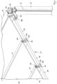
- Eine in
Fig. 1 dargestellte Dachkonstruktion 10 weist einen vorzugsweise ebenen Tragrahmen 11 auf, der eine rechteckige Konfiguration besitzt und zwei parallel zueinander und in gegenseitigem Abstand angeordnete Längsträger 12 und zwei parallel zueinander und in gegenseitigem Abstand angeordnete Querträger 13 aufweist. Der Tragrahmen 11 verläuft vorzugsweise in einer Tragrahmen-Ebene und kann horizontal ausgerichtet oder gegenüber einer Horizontalen geneigt angeordnet sein. Der Tragrahmen 11 ist mittels einer Tragkonstruktion 14 abgestützt, die im dargestellten Ausführungsbeispiels zwei in zwei Eckpunkten des Tragrahmens 11 angeordnete vertikale Stützen 17 und eine nur schematisch angeordnete Gebäudewand 30 umfasst. - Die Längsträger 12 und die Querträger 13 umgeben ein im Inneren des Tragrahmens 11 liegendes Rahmenfeld 11a, das mittels mehrerer Sparren 15 in mehrere Dachfelder 20 unterteilt ist. Im dargestellten Ausführungsbeispiel sind vier Sparren 15 vorhanden, die das Rahmenfeld 11a in fünf vorzugsweise etwa gleich große, rechteckige Dachfelder 20 unterteilen. Die Dachfelder 20 sind jeweils mittels einer ebenen Abdeckplatte 16, die aus Glas bestehen kann, vollständig abgedeckt. Jede Abdeckplatte 16 weist eine lange Längsachse LL und eine senkrecht dazu verlaufende kurze Längsachse LK auf, wobei die Abdeckplatten 16 zumindest um die lange Längsachse LL relativ zu einer Horizontalen geneigt angeordnet sind.
- Benachbarte Abdeckplatten 16 sind mit jeweils einem Ende an jeweils einem der Sparren 15 gelagert, wie es insbesondere in
Fig. 2 dargestellt ist. Der Sparren 15 weist in einer Seitenwand 15a eine 1. Auflagerfläche 26 auf, auf die ein Randbereich einer der Abdeckplatten 16 aufgelagert ist. Schräg oberhalb der 1. Auflagerfläche 26 ist in dem Sparren 15 eine kammerartige Ausnehmung 29 ausgebildet, auf deren Boden eine 2. Auflagerfläche 27 gebildet ist. Eine benachbarte weitere Abdeckplatte 16 ist mit ihrem Randbereich in die Ausnehmung 29 eingesetzt und auf die 2. Auflagerfläche 27 aufgelagert. - In dem Sparren 15 ist ein Wasserkanal 18 ausgebildet, der als nach oben offene, U-förmige Rinne ausgestaltet ist und in Längsrichtung des Sparrens 15 verläuft und an dessen axialem Ende in einem Wasserauslass 28 mündet, der in
Fig. 3 ersichtlich ist. Die 1. Auflagerfläche 26 ist im oberen Bereich des Wasserkanals 18 so angeordnet, dass Regenwasser, das sich auf der Oberseite der auf die 1. Auflagerfläche 26 aufgelagerten Abdeckplatte 16 sammelt, in Folge der Neigung der Abdeckplatte 16 von oben in den Wasserkanal 18 einströmt oder eintropft, wie es durch den Pfeil W1 dargestellt ist. Das Wasser wird dann im Wasserkanal 18 abgeleitet und durch den Wasserauslass 28 abgeführt. - Im Strömungsweg von der Oberseite der Abdeckplatte 16 bis zum Wasserkanal 18 ist eine Filtervorrichtung 31 vorgesehen, die von dem Wasser durchströmt wird, bevor das Wasser in den Wasserkanal 18 eintritt. Auf diese Weise wird verhindert, dass Fremdkörper in den Wasserkanal 18 gelangen und diesen verstopfen können. Als Filtervorrichtung 31 ist eine leistenförmige Borstendichtung 32 vorgesehen, die von einer langgestreckten Anordnung von Borsten und/oder Borstenbündel gebildet ist und an dem Sparren 15 so oberhalb der Abdeckplatte 16 angebracht ist, dass die Borsten und/oder Borstenbündel mit ihren Enden von oben auf der Oberseite der Abdeckplatte 16 aufsitzen. Die Filtervorrichtung 31 bzw. die Borstendichtung 32 dient zusätzlich als Niederhalter, der die Abdeckplatte 16 gegen die 1. Auflagerfläche 26 spannt.
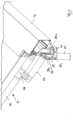
- An dem gemäß
Fig. 1 unteren, der Gebäudewand 30 abgewandten axialen Ende des Wasserkanals 18 ist der Wasserauslass 28 angeordnet, in den ein T-förmiges Verbindungsstück 33 mit einem Anschluss 35 eingesetzt ist (s.Fig. 4 ). Das Verbindungsstück 33 besitzt weitere Anschlüsse 36 und 37, auf die jeweils ein Schlauchabschnitt 34 eines flexiblen Wellschlauches oder ein Rohrabschnitt aufgesetzt sind. Die Rohr- oder Schlauchabschnitte 34 bilden zusammen mit den Verbindungsstücken 33 einen Sammelkanal 21, der das aus dem Wasserkanälen 18 ausströmende Wasser aufnimmt. Der Sammelkanal 21 verläuft im Wesentlichen senkrecht zu den Sparren 15 und insbesondere innerhalb des gemäßFig. 1 vorderen bzw. unteren, der Gebäudewand 30 abgewandten Querträgers 13. - Wie aus
Fig. 3 ersichtlich ist, ist an dem dem Wasserauslass 28 entgegengesetzten axialen Ende des Wasserkanals 18 ein weiterer Wasserauslass 42 vorgesehen, der auf einem höheren Höhenniveau als der Wasserauslass 28 liegt. Der weitere Wasserauslass 42 mündet über ein weiteres Verbindungsstück 43 in einem Überlaufkanal 41, der den gleichen konstruktiven Aufbau wie der Sammelkanal 21 aufweisen kann, d.h. er kann über rohrförmige weitere Verbindungsstücke mit den einzelnen Wasserkanälen der Sparren verbunden sein, wobei zwischen den weiteren Verbindungsstücken jeweils Rohr- oder Schlauchabschnitte verlaufen. - Der Sammelkanal 21 ist über ein gekrümmtes rohrförmiges 1. Mündungsstück 38 mit einem weiterführenden 1. Ableitungskanal 23 verbunden. Der 1. Ableitungskanal 23 ist von einem Rohr oder einem Schlauch, insbesondere einem Wellschlauch, gebildet und verläuft parallel zum Sammelkanal 21 innerhalb des Querträgers 13.
- An seinem dem 1. Mündungsstück 38 entgegengesetzten, stromab liegenden Ende ist der 1. Ableitungskanal 23 an ein 2. Mündungsstück 39 angeschlossen, wie es in
Fig. 4 und insbesondere inFig. 5 dargestellt ist. Das 2. Mündungsstück 39 besitzt einen nach oben offenen Sammeltank 44, der einen als Überlauf dienenden oberen Auslass 40 aufweist und in den der 1. Ableitungskanal 23 über einen 1. oberen Anschluss 39a mündet. Ein unterer Anschluss 39c ist mit einem weiterführenden 2. Ableitungskanal 24 verbunden, der sich im Wesentlichen vertikal erstreckt und von einem Rohr oder einem Schlauch insbesondere in Form eines Wellschlauchs gebildet ist. Der 2. Ableitungskanal 24 verläuft innerhalb der Stütze 17 und ist an seinem unteren Ende entweder in nicht dargestellter Weise an eine weiterführende Leitung oder eine Kanalisation angeschlossen oder mündet in der Umgebung. - Der Überlaufkanal 41 verläuft in oder an dem der Gebäudewand zugewandten Querträger 13. Der Überlaufkanal 41 kann das Wasser entweder unabhängig von dem vertikalen 2. Ableitungskanal 24 abführen oder alternativ in dem vertikalen 2.
- Ableitungskanal 24 münden. Bei dem in
Figur 5 dargestellten Ausführungsbeispiel verläuft der Überlaufkanal 41 durch den Längsträger 12 hindurch bis zu dem 2. Mündungsstück 39 und mündet dort über einen zweiten oberen Anschluss 39b in dem Sammeltank 44. - Das sich auf den Abdeckplatten 16 der Dachkonstruktion 10 sammelnde Wasser fließt in genannter Weise in die Wasserkanäle 18 der Sparren 15 ein und strömt in diesem zu den jeweiligen Wasserauslass 28 und durch die dort angeordneten Verbindungsstücke in den Sammelkanal 21. Aus dem Sammelkanal 21 fließt das Wasser über das 1. Mündungsstück 38 in den 1. Ableitungskanal 23 bis zu dem 2. Mündungsstück 39 und von diesem in den 2. Ableitungskanal 24.
- Falls der 2. Ableitungskanal die anfallende Wassermenge nicht aufnehmen kann oder verstopft ist, wird das Wasser zunächst in dem Sammeltank 44 aufgenommen. Falls dieser vollständig gefüllt ist, tritt überschüssiges Wasser an dem Auslass 40 aus, wie es durch den Pfeil W2 in
Fig. 4 angedeutet ist. - Falls der Sammelkanal 21 und/oder der 1. Ableitungskanal 23 verstopft sein sollten, kann das Wasser aus den Wasserkanälen 18 der Sparren 15 nicht in ausreichendem Maße ablaufen, so dass der Wasserstand in den Wasserkanälen 18 der Sparren 15 ansteigt, bis das Wasser eine vorbestimmte Höhe erreicht hat, so dass es durch den weiteren Wasserauslass 42 der Sparren 18 und den Überlaufkanal 41 abfließen und zu dem 2. Mündungsstück 39 fließen kann, dort den Sammeltank 44 durchströmt und durch den 2. Ableitungskanal 24 abgeführt wird.
Claims (20)
- Dachkonstruktion (10) mit einem Tragrahmen (11), der mittels einer Tragkonstruktion (14) der Dachkonstruktion (10) abgestützt ist und zumindest zwei parallel zueinander und in gegenseitigem Abstand angeordnete Längsträger (12) und zumindest zwei parallel zueinander und in gegenseitigem Abstand angeordnete Querträger (13) aufweist und der ein Rahmenfeld (11a) umgibt, und mit zumindest einem Sparren (15), der die Querträger (13) miteinander verbindet, im Abstand zu den Längsträgern (12) verläuft und das Rahmenfeld (11a) in mehrere Dachfelder (20) unterteilt, wobei zumindest eines der Dachfelder (20) mittels einer Abdeckplatte (16) abgedeckt ist und wobei in oder an dem Sparren (15) ein Wasserkanal (18) ausgebildet ist, der in Längsrichtung des Sparrens (15) verläuft und der in seinem axialen Endbereich über einen Wasserauslass (28) in einem Sammelkanal (21) mündet, wobei der Sammelkanal (21) zumindest abschnittsweise von einem Rohr oder einem Schlauch gebildet ist, dadurch gekennzeichnet, dass ein Überlaufkanal (41) vorgesehen ist, der an dem dem Wasserauslass (28) entgegengesetzten axialen Ende des Wasserkanals (18) des Sparrens (15) angeordnet ist, wobei der Überlaufkanal (41) so ausgebildet ist, dass das Wasser aus dem Wasserkanal (18) des Sparrens (15) in den Überlaufkanal (41) einströmt und durch diesen abgeleitet wird, wenn innerhalb des Wasserkanals (18) des Sparrens (15) ein vorbestimmtes Wasserniveau erreicht ist
- Dachkonstruktion nach Anspruch 1, dadurch gekennzeichnet, dass der Überlaufkanal (41) über rohrförmige Verbindungstücke (43) mit den Wasserkanälen (18) der Sparren (15) verbunden ist.
- Dachkonstruktion nach Anspruch 2, dadurch gekennzeichnet, dass zwischen den Verbindungsstücken (43) jeweils Rohr- oder Schlauchabschnitte verlaufen.
- Dachkonstruktion nach einem der Ansprüche 1 bis 3,
dadurch gekennzeichnet, dass der Überlaufkanal (41) in oder an dem Querträger (13) verläuft. - Dachkonstruktion nach Anspruch 4, dadurch gekennzeichnet, dass der Überlaufkanal (41) am Ende des Querträgers (13) in einen der Längsträger (12) übergeht.
- Dachkonstruktion nach einem der Ansprüche 1 bis 5,
dadurch gekennzeichnet, dass der Sammelkanal (21) horizontal oder unter einem Neigungswinkel von 0,1° bis 5° oder um ± 1° bis 3° gegenüber der Horizontalen geneigt verläuft. - Dachkonstruktion nach einem der Ansprüche 1 bis 6,
dadurch gekennzeichnet, dass der Sammelkanal (21) innerhalb eines der Querträger (13) verläuft. - Dachkonstruktion nach einem der Ansprüche 1 bis 7,
dadurch gekennzeichnet, dass ein Verbindungsstück (33) mehrere Anschlüsse (35, 36, 37) aufweist und mit einem der Anschlüsse (35) mit dem Wasserauslass (28) des Wasserkanals (18) und mit zumindest einem weiteren Anschluss (36, 37) mit einem Schlauchabschnitt (34) des Sammelkanals (21) verbunden ist. - Dachkonstruktion nach einem der Ansprüche 1 bis 8,
dadurch gekennzeichnet, dass der Sammelkanal (21) über ein 1. Mündungsstück (38) in einem weiterführenden 1. Ableitungskanal (23) mündet. - Dachkonstruktion nach Anspruch 9, dadurch gekennzeichnet, dass der 1. Ableitungskanal (23) zumindest abschnittsweise von einem Rohr oder einem Schlauch gebildet ist.
- Dachkonstruktion nach Anspruch 9 oder 10, dadurch gekennzeichnet, dass der 1. Ableitungskanal (23) horizontal oder unter einem Neigungswinkel von 0,1° bis 5° oder um ± 1° bis 3° gegenüber der Horizontalen geneigt verläuft.
- Dachkonstruktion nach einem der Ansprüche 9 bis 11,
dadurch gekennzeichnet, dass der 1. Ableitungskanal (23) innerhalb eines der Querträger (13) verläuft. - Dachkonstruktion nach einem der Ansprüche 9 bis 12,
dadurch gekennzeichnet, dass der 1. Ableitungskanal (23) an seinem stromab liegenden Ende über ein 2. Mündungsstück (39) in einem weiterführenden 2. Ableitungskanal (24) mündet. - Dachkonstruktion nach Anspruch 13, dadurch gekennzeichnet, dass der Überlaufkanal (41) in dem 2. Ableitungskanal (24) mündet.
- Dachkonstruktion nach Anspruch 13 oder 14, dadurch gekennzeichnet, dass der Überlaufkanal (41) an das 2. Mündungsstück (29) angeschlossen ist.
- Dachkonstruktion nach einem der Ansprüche 13 bis 15,
dadurch gekennzeichnet, dass der 2. Ableitungskanal (24) zumindest abschnittsweise von einem Rohr oder einem Schlauch gebildet ist. - Dachkonstruktion nach einem der Ansprüche 13 bis 16,
dadurch gekennzeichnet, dass die Tragkonstruktion (14) zumindest eine vertikale Stütze (17) aufweist und dass der 2. Ableitungskanal (24) an oder innerhalb der Stütze (17) verläuft. - Dachkonstruktion nach einem der Ansprüche 1 bis 17,
dadurch gekennzeichnet, dass im Strömungsweg des Wassers von der Oberseite der Abdeckplatte (16) bis zum Wasserkanal (18) eine Filtervorrichtung (31) angeordnet ist, die von dem Wasser durchströmt ist. - Dachkonstruktion nach Anspruch 18, dadurch gekennzeichnet, dass die Filtervorrichtung (31) eine Borstendichtung (32) aufweist.
- Dachkonstruktion nach Anspruch 18 oder 19, dadurch gekennzeichnet, dass die Filtervorrichtung (31) als Niederhalter dient, der die Abdeckplatte (16) gegen den Sparren (15) spannt.
Applications Claiming Priority (1)
| Application Number | Priority Date | Filing Date | Title |
|---|---|---|---|
| DE102021118544.0A DE102021118544A1 (de) | 2021-07-19 | 2021-07-19 | Dachkonstruktion |
Publications (2)
| Publication Number | Publication Date |
|---|---|
| EP4123100A1 EP4123100A1 (de) | 2023-01-25 |
| EP4123100B1 true EP4123100B1 (de) | 2025-06-25 |
Family
ID=82655123
Family Applications (1)
| Application Number | Title | Priority Date | Filing Date |
|---|---|---|---|
| EP22185481.3A Active EP4123100B1 (de) | 2021-07-19 | 2022-07-18 | Dachkonstruktion |
Country Status (2)
| Country | Link |
|---|---|
| EP (1) | EP4123100B1 (de) |
| DE (1) | DE102021118544A1 (de) |
Family Cites Families (10)
| Publication number | Priority date | Publication date | Assignee | Title |
|---|---|---|---|---|
| GB2152092B (en) | 1983-12-22 | 1987-04-08 | Conroy Fitzpatrick Limited | Gutter connections accommadating expansion/contraction and obviating overflow |
| DE3637715A1 (de) * | 1986-11-05 | 1988-05-19 | Herbert Kleser | Lichtdurchlaessige ueberdachung, insbesondere fuer wintergaerten o.dgl. |
| WO2004057129A1 (en) * | 2002-12-23 | 2004-07-08 | Mara-Institut D.O.O. | The roofing-drainage system for large-span buildings |
| CN2685431Y (zh) * | 2004-03-08 | 2005-03-16 | 民夏铝业(常熟)有限公司 | 拼装式水落管 |
| GB0409172D0 (en) * | 2004-04-24 | 2004-05-26 | Glazing System Profiles Ltd | Canopy |
| JP6995647B2 (ja) | 2018-01-29 | 2022-01-14 | 四国化成工業株式会社 | 簡易構造物 |
| BE1026031B1 (nl) | 2018-02-20 | 2019-09-20 | Brustor Nv | Zonwering |
| EP3604704B1 (de) * | 2018-08-03 | 2024-02-28 | Weinor GmbH & Co. KG | Überdachung mit optimierter regenwasserführung |
| CN210976385U (zh) * | 2019-10-29 | 2020-07-10 | 广东华盈钢构有限公司 | 一种门式雨棚结构 |
| DE102020124831A1 (de) | 2020-09-23 | 2022-03-24 | Jürgen Grimmeisen | Dachkonstruktion für einen Carport oder einen Unterstand |
-
2021
- 2021-07-19 DE DE102021118544.0A patent/DE102021118544A1/de active Pending
-
2022
- 2022-07-18 EP EP22185481.3A patent/EP4123100B1/de active Active
Also Published As
| Publication number | Publication date |
|---|---|
| DE102021118544A1 (de) | 2023-01-19 |
| EP4123100A1 (de) | 2023-01-25 |
Similar Documents
| Publication | Publication Date | Title |
|---|---|---|
| DE29502895U1 (de) | Regenwasserfiltereinrichtung | |
| EP3974600A1 (de) | Dachkonstruktion für einen carport oder einen unterstand | |
| DE3829384A1 (de) | Vorrichtung zum abweisen von verunreinigungen wie laub u. dgl. an dachrinnen | |
| EP4123100B1 (de) | Dachkonstruktion | |
| EP3604704B1 (de) | Überdachung mit optimierter regenwasserführung | |
| EP1826334B1 (de) | Notüberlauf | |
| EP0767278B1 (de) | Versickerungsrinnensystem | |
| DE19812398C2 (de) | Verfahren und Vorrichtung zur Ableitung von Wasser von einer im wesentlichen ebenen Fläche | |
| WO2010022704A2 (de) | Zisterne mit einem regenwasserfilter im zulauf sowie ein filtergehäuse für einen regenwasserfilter | |
| EP1690989B1 (de) | Versickerungsvorrichtung | |
| DE102007047064A1 (de) | Ablaufrinne mit Abdeckung | |
| EP3075920A1 (de) | Abschlussleiste und verfahren zum montieren einer abschlussleiste | |
| DE8334717U1 (de) | Schlitzrinne zur bodenentwaesserung | |
| EP4163452B1 (de) | Schrägdachaufbau | |
| DE8618206U1 (de) | Gleiswanne | |
| DE102008011125A1 (de) | Abdeckung für Schwallwasserbehälter/Überlaufrinne | |
| AT510541B1 (de) | Laub-sammelbehälter | |
| DE19602414C2 (de) | Vorrichtung zum Sammeln und Verrieseln von Oberflächenwasser | |
| DE10017890B4 (de) | Entwässerungssystem für Balkone | |
| DE29616665U1 (de) | Balkon | |
| AT513278B1 (de) | Gerinne zur Abfuhr von Oberflächenwässern | |
| DE9011346U1 (de) | Fallrohr für Regensammler | |
| DE202022105812U1 (de) | Gehäuse für ein technisches Versorgungs- und Infrastrukturgebäude, insbesondere eine Transformatorstation, mit einer begrünbaren Dachfläche | |
| DE102021111373A1 (de) | Dachkonstruktion | |
| EP1211360B1 (de) | Vorrichtung zum Reinigen eines Mehrphasen-Gemisches von insbesondere Dachablauf- und/oder Zisternen-Rohwasser |
Legal Events
| Date | Code | Title | Description |
|---|---|---|---|
| PUAI | Public reference made under article 153(3) epc to a published international application that has entered the european phase |
Free format text: ORIGINAL CODE: 0009012 |
|
| STAA | Information on the status of an ep patent application or granted ep patent |
Free format text: STATUS: THE APPLICATION HAS BEEN PUBLISHED |
|
| AK | Designated contracting states |
Kind code of ref document: A1 Designated state(s): AL AT BE BG CH CY CZ DE DK EE ES FI FR GB GR HR HU IE IS IT LI LT LU LV MC MK MT NL NO PL PT RO RS SE SI SK SM TR |
|
| STAA | Information on the status of an ep patent application or granted ep patent |
Free format text: STATUS: REQUEST FOR EXAMINATION WAS MADE |
|
| 17P | Request for examination filed |
Effective date: 20230725 |
|
| RBV | Designated contracting states (corrected) |
Designated state(s): AL AT BE BG CH CY CZ DE DK EE ES FI FR GB GR HR HU IE IS IT LI LT LU LV MC MK MT NL NO PL PT RO RS SE SI SK SM TR |
|
| GRAP | Despatch of communication of intention to grant a patent |
Free format text: ORIGINAL CODE: EPIDOSNIGR1 |
|
| STAA | Information on the status of an ep patent application or granted ep patent |
Free format text: STATUS: GRANT OF PATENT IS INTENDED |
|
| INTG | Intention to grant announced |
Effective date: 20250212 |
|
| GRAS | Grant fee paid |
Free format text: ORIGINAL CODE: EPIDOSNIGR3 |
|
| GRAA | (expected) grant |
Free format text: ORIGINAL CODE: 0009210 |
|
| STAA | Information on the status of an ep patent application or granted ep patent |
Free format text: STATUS: THE PATENT HAS BEEN GRANTED |
|
| AK | Designated contracting states |
Kind code of ref document: B1 Designated state(s): AL AT BE BG CH CY CZ DE DK EE ES FI FR GB GR HR HU IE IS IT LI LT LU LV MC MK MT NL NO PL PT RO RS SE SI SK SM TR |
|
| REG | Reference to a national code |
Ref country code: GB Ref legal event code: FG4D Free format text: NOT ENGLISH |
|
| REG | Reference to a national code |
Ref country code: CH Ref legal event code: EP |
|
| REG | Reference to a national code |
Ref country code: CH Ref legal event code: EP |
|
| REG | Reference to a national code |
Ref country code: IE Ref legal event code: FG4D Free format text: LANGUAGE OF EP DOCUMENT: GERMAN |
|
| REG | Reference to a national code |
Ref country code: DE Ref legal event code: R096 Ref document number: 502022004385 Country of ref document: DE |
|
| REG | Reference to a national code |
Ref country code: NL Ref legal event code: FP |
|
| PGFP | Annual fee paid to national office [announced via postgrant information from national office to epo] |
Ref country code: NL Payment date: 20250804 Year of fee payment: 4 |
|
| PG25 | Lapsed in a contracting state [announced via postgrant information from national office to epo] |
Ref country code: FI Free format text: LAPSE BECAUSE OF FAILURE TO SUBMIT A TRANSLATION OF THE DESCRIPTION OR TO PAY THE FEE WITHIN THE PRESCRIBED TIME-LIMIT Effective date: 20250625 |
|
| PGFP | Annual fee paid to national office [announced via postgrant information from national office to epo] |
Ref country code: DE Payment date: 20250714 Year of fee payment: 4 |
|
| REG | Reference to a national code |
Ref country code: LT Ref legal event code: MG9D |
|
| PG25 | Lapsed in a contracting state [announced via postgrant information from national office to epo] |
Ref country code: GR Free format text: LAPSE BECAUSE OF FAILURE TO SUBMIT A TRANSLATION OF THE DESCRIPTION OR TO PAY THE FEE WITHIN THE PRESCRIBED TIME-LIMIT Effective date: 20250926 |
|
| PGFP | Annual fee paid to national office [announced via postgrant information from national office to epo] |
Ref country code: NO Payment date: 20250910 Year of fee payment: 4 |
|
| P01 | Opt-out of the competence of the unified patent court (upc) registered |
Free format text: CASE NUMBER: UPC_APP_6033_4123100/2025 Effective date: 20250904 |
|
| PGFP | Annual fee paid to national office [announced via postgrant information from national office to epo] |
Ref country code: IT Payment date: 20250731 Year of fee payment: 4 |
|
| PG25 | Lapsed in a contracting state [announced via postgrant information from national office to epo] |
Ref country code: BG Free format text: LAPSE BECAUSE OF FAILURE TO SUBMIT A TRANSLATION OF THE DESCRIPTION OR TO PAY THE FEE WITHIN THE PRESCRIBED TIME-LIMIT Effective date: 20250625 |
|
| PGFP | Annual fee paid to national office [announced via postgrant information from national office to epo] |
Ref country code: BE Payment date: 20250804 Year of fee payment: 4 |
|
| PG25 | Lapsed in a contracting state [announced via postgrant information from national office to epo] |
Ref country code: HR Free format text: LAPSE BECAUSE OF FAILURE TO SUBMIT A TRANSLATION OF THE DESCRIPTION OR TO PAY THE FEE WITHIN THE PRESCRIBED TIME-LIMIT Effective date: 20250625 |
|
| PGFP | Annual fee paid to national office [announced via postgrant information from national office to epo] |
Ref country code: FR Payment date: 20250729 Year of fee payment: 4 Ref country code: AT Payment date: 20251020 Year of fee payment: 4 |
|
| PGFP | Annual fee paid to national office [announced via postgrant information from national office to epo] |
Ref country code: CH Payment date: 20250903 Year of fee payment: 4 |
|
| PG25 | Lapsed in a contracting state [announced via postgrant information from national office to epo] |
Ref country code: RS Free format text: LAPSE BECAUSE OF FAILURE TO SUBMIT A TRANSLATION OF THE DESCRIPTION OR TO PAY THE FEE WITHIN THE PRESCRIBED TIME-LIMIT Effective date: 20250925 |
|
| PG25 | Lapsed in a contracting state [announced via postgrant information from national office to epo] |
Ref country code: LV Free format text: LAPSE BECAUSE OF FAILURE TO SUBMIT A TRANSLATION OF THE DESCRIPTION OR TO PAY THE FEE WITHIN THE PRESCRIBED TIME-LIMIT Effective date: 20250625 |
|
| PG25 | Lapsed in a contracting state [announced via postgrant information from national office to epo] |
Ref country code: PT Free format text: LAPSE BECAUSE OF FAILURE TO SUBMIT A TRANSLATION OF THE DESCRIPTION OR TO PAY THE FEE WITHIN THE PRESCRIBED TIME-LIMIT Effective date: 20251027 |
|
| PG25 | Lapsed in a contracting state [announced via postgrant information from national office to epo] |
Ref country code: IS Free format text: LAPSE BECAUSE OF FAILURE TO SUBMIT A TRANSLATION OF THE DESCRIPTION OR TO PAY THE FEE WITHIN THE PRESCRIBED TIME-LIMIT Effective date: 20251025 |
|
| PG25 | Lapsed in a contracting state [announced via postgrant information from national office to epo] |
Ref country code: SM Free format text: LAPSE BECAUSE OF FAILURE TO SUBMIT A TRANSLATION OF THE DESCRIPTION OR TO PAY THE FEE WITHIN THE PRESCRIBED TIME-LIMIT Effective date: 20250625 |
|
| PG25 | Lapsed in a contracting state [announced via postgrant information from national office to epo] |
Ref country code: CZ Free format text: LAPSE BECAUSE OF FAILURE TO SUBMIT A TRANSLATION OF THE DESCRIPTION OR TO PAY THE FEE WITHIN THE PRESCRIBED TIME-LIMIT Effective date: 20250625 |
|
| PG25 | Lapsed in a contracting state [announced via postgrant information from national office to epo] |
Ref country code: PL Free format text: LAPSE BECAUSE OF FAILURE TO SUBMIT A TRANSLATION OF THE DESCRIPTION OR TO PAY THE FEE WITHIN THE PRESCRIBED TIME-LIMIT Effective date: 20250625 |
|
| PG25 | Lapsed in a contracting state [announced via postgrant information from national office to epo] |
Ref country code: EE Free format text: LAPSE BECAUSE OF FAILURE TO SUBMIT A TRANSLATION OF THE DESCRIPTION OR TO PAY THE FEE WITHIN THE PRESCRIBED TIME-LIMIT Effective date: 20250625 |
|
| PG25 | Lapsed in a contracting state [announced via postgrant information from national office to epo] |
Ref country code: SK Free format text: LAPSE BECAUSE OF FAILURE TO SUBMIT A TRANSLATION OF THE DESCRIPTION OR TO PAY THE FEE WITHIN THE PRESCRIBED TIME-LIMIT Effective date: 20250625 |
|
| PG25 | Lapsed in a contracting state [announced via postgrant information from national office to epo] |
Ref country code: ES Free format text: LAPSE BECAUSE OF FAILURE TO SUBMIT A TRANSLATION OF THE DESCRIPTION OR TO PAY THE FEE WITHIN THE PRESCRIBED TIME-LIMIT Effective date: 20250625 |
|
| PG25 | Lapsed in a contracting state [announced via postgrant information from national office to epo] |
Ref country code: RO Free format text: LAPSE BECAUSE OF FAILURE TO SUBMIT A TRANSLATION OF THE DESCRIPTION OR TO PAY THE FEE WITHIN THE PRESCRIBED TIME-LIMIT Effective date: 20250625 Ref country code: LU Free format text: LAPSE BECAUSE OF NON-PAYMENT OF DUE FEES Effective date: 20250718 |
|
| PG25 | Lapsed in a contracting state [announced via postgrant information from national office to epo] |
Ref country code: MC Free format text: LAPSE BECAUSE OF FAILURE TO SUBMIT A TRANSLATION OF THE DESCRIPTION OR TO PAY THE FEE WITHIN THE PRESCRIBED TIME-LIMIT Effective date: 20250625 |
|
| PG25 | Lapsed in a contracting state [announced via postgrant information from national office to epo] |
Ref country code: DK Free format text: LAPSE BECAUSE OF FAILURE TO SUBMIT A TRANSLATION OF THE DESCRIPTION OR TO PAY THE FEE WITHIN THE PRESCRIBED TIME-LIMIT Effective date: 20250625 |