EP4123146B1 - Architectures de moteur refroidi à double cycle - Google Patents
Architectures de moteur refroidi à double cycle Download PDFInfo
- Publication number
- EP4123146B1 EP4123146B1 EP22186554.6A EP22186554A EP4123146B1 EP 4123146 B1 EP4123146 B1 EP 4123146B1 EP 22186554 A EP22186554 A EP 22186554A EP 4123146 B1 EP4123146 B1 EP 4123146B1
- Authority
- EP
- European Patent Office
- Prior art keywords
- hydrogen
- turbine
- compressor
- conduit
- heat exchanger
- Prior art date
- Legal status (The legal status is an assumption and is not a legal conclusion. Google has not performed a legal analysis and makes no representation as to the accuracy of the status listed.)
- Active
Links
Images


Classifications
-
- F—MECHANICAL ENGINEERING; LIGHTING; HEATING; WEAPONS; BLASTING
- F02—COMBUSTION ENGINES; HOT-GAS OR COMBUSTION-PRODUCT ENGINE PLANTS
- F02C—GAS-TURBINE PLANTS; AIR INTAKES FOR JET-PROPULSION PLANTS; CONTROLLING FUEL SUPPLY IN AIR-BREATHING JET-PROPULSION PLANTS
- F02C3/00—Gas-turbine plants characterised by the use of combustion products as the working fluid
- F02C3/20—Gas-turbine plants characterised by the use of combustion products as the working fluid using a special fuel, oxidant, or dilution fluid to generate the combustion products
- F02C3/22—Gas-turbine plants characterised by the use of combustion products as the working fluid using a special fuel, oxidant, or dilution fluid to generate the combustion products the fuel or oxidant being gaseous at standard temperature and pressure
-
- F—MECHANICAL ENGINEERING; LIGHTING; HEATING; WEAPONS; BLASTING
- F02—COMBUSTION ENGINES; HOT-GAS OR COMBUSTION-PRODUCT ENGINE PLANTS
- F02C—GAS-TURBINE PLANTS; AIR INTAKES FOR JET-PROPULSION PLANTS; CONTROLLING FUEL SUPPLY IN AIR-BREATHING JET-PROPULSION PLANTS
- F02C7/00—Features, components parts, details or accessories, not provided for in, or of interest apart form groups F02C1/00 - F02C6/00; Air intakes for jet-propulsion plants
- F02C7/12—Cooling of plants
- F02C7/14—Cooling of plants of fluids in the plant, e.g. lubricant or fuel
- F02C7/141—Cooling of plants of fluids in the plant, e.g. lubricant or fuel of working fluid
-
- F—MECHANICAL ENGINEERING; LIGHTING; HEATING; WEAPONS; BLASTING
- F02—COMBUSTION ENGINES; HOT-GAS OR COMBUSTION-PRODUCT ENGINE PLANTS
- F02C—GAS-TURBINE PLANTS; AIR INTAKES FOR JET-PROPULSION PLANTS; CONTROLLING FUEL SUPPLY IN AIR-BREATHING JET-PROPULSION PLANTS
- F02C7/00—Features, components parts, details or accessories, not provided for in, or of interest apart form groups F02C1/00 - F02C6/00; Air intakes for jet-propulsion plants
- F02C7/12—Cooling of plants
- F02C7/16—Cooling of plants characterised by cooling medium
- F02C7/18—Cooling of plants characterised by cooling medium the medium being gaseous, e.g. air
-
- F—MECHANICAL ENGINEERING; LIGHTING; HEATING; WEAPONS; BLASTING
- F02—COMBUSTION ENGINES; HOT-GAS OR COMBUSTION-PRODUCT ENGINE PLANTS
- F02C—GAS-TURBINE PLANTS; AIR INTAKES FOR JET-PROPULSION PLANTS; CONTROLLING FUEL SUPPLY IN AIR-BREATHING JET-PROPULSION PLANTS
- F02C7/00—Features, components parts, details or accessories, not provided for in, or of interest apart form groups F02C1/00 - F02C6/00; Air intakes for jet-propulsion plants
- F02C7/22—Fuel supply systems
- F02C7/224—Heating fuel before feeding to the burner
-
- F—MECHANICAL ENGINEERING; LIGHTING; HEATING; WEAPONS; BLASTING
- F02—COMBUSTION ENGINES; HOT-GAS OR COMBUSTION-PRODUCT ENGINE PLANTS
- F02C—GAS-TURBINE PLANTS; AIR INTAKES FOR JET-PROPULSION PLANTS; CONTROLLING FUEL SUPPLY IN AIR-BREATHING JET-PROPULSION PLANTS
- F02C7/00—Features, components parts, details or accessories, not provided for in, or of interest apart form groups F02C1/00 - F02C6/00; Air intakes for jet-propulsion plants
- F02C7/32—Arrangement, mounting, or driving, of auxiliaries
-
- F—MECHANICAL ENGINEERING; LIGHTING; HEATING; WEAPONS; BLASTING
- F02—COMBUSTION ENGINES; HOT-GAS OR COMBUSTION-PRODUCT ENGINE PLANTS
- F02C—GAS-TURBINE PLANTS; AIR INTAKES FOR JET-PROPULSION PLANTS; CONTROLLING FUEL SUPPLY IN AIR-BREATHING JET-PROPULSION PLANTS
- F02C9/00—Controlling gas-turbine plants; Controlling fuel supply in air- breathing jet-propulsion plants
- F02C9/16—Control of working fluid flow
- F02C9/18—Control of working fluid flow by bleeding, bypassing or acting on variable working fluid interconnections between turbines or compressors or their stages
-
- F—MECHANICAL ENGINEERING; LIGHTING; HEATING; WEAPONS; BLASTING
- F05—INDEXING SCHEMES RELATING TO ENGINES OR PUMPS IN VARIOUS SUBCLASSES OF CLASSES F01-F04
- F05D—INDEXING SCHEME FOR ASPECTS RELATING TO NON-POSITIVE-DISPLACEMENT MACHINES OR ENGINES, GAS-TURBINES OR JET-PROPULSION PLANTS
- F05D2220/00—Application
- F05D2220/30—Application in turbines
- F05D2220/32—Application in turbines in gas turbines
- F05D2220/323—Application in turbines in gas turbines for aircraft propulsion, e.g. jet engines
-
- F—MECHANICAL ENGINEERING; LIGHTING; HEATING; WEAPONS; BLASTING
- F05—INDEXING SCHEMES RELATING TO ENGINES OR PUMPS IN VARIOUS SUBCLASSES OF CLASSES F01-F04
- F05D—INDEXING SCHEME FOR ASPECTS RELATING TO NON-POSITIVE-DISPLACEMENT MACHINES OR ENGINES, GAS-TURBINES OR JET-PROPULSION PLANTS
- F05D2260/00—Function
- F05D2260/20—Heat transfer, e.g. cooling
- F05D2260/211—Heat transfer, e.g. cooling by intercooling, e.g. during a compression cycle
-
- F—MECHANICAL ENGINEERING; LIGHTING; HEATING; WEAPONS; BLASTING
- F05—INDEXING SCHEMES RELATING TO ENGINES OR PUMPS IN VARIOUS SUBCLASSES OF CLASSES F01-F04
- F05D—INDEXING SCHEME FOR ASPECTS RELATING TO NON-POSITIVE-DISPLACEMENT MACHINES OR ENGINES, GAS-TURBINES OR JET-PROPULSION PLANTS
- F05D2260/00—Function
- F05D2260/20—Heat transfer, e.g. cooling
- F05D2260/213—Heat transfer, e.g. cooling by the provision of a heat exchanger within the cooling circuit
-
- F—MECHANICAL ENGINEERING; LIGHTING; HEATING; WEAPONS; BLASTING
- F05—INDEXING SCHEMES RELATING TO ENGINES OR PUMPS IN VARIOUS SUBCLASSES OF CLASSES F01-F04
- F05D—INDEXING SCHEME FOR ASPECTS RELATING TO NON-POSITIVE-DISPLACEMENT MACHINES OR ENGINES, GAS-TURBINES OR JET-PROPULSION PLANTS
- F05D2260/00—Function
- F05D2260/20—Heat transfer, e.g. cooling
- F05D2260/232—Heat transfer, e.g. cooling characterized by the cooling medium
-
- F—MECHANICAL ENGINEERING; LIGHTING; HEATING; WEAPONS; BLASTING
- F05—INDEXING SCHEMES RELATING TO ENGINES OR PUMPS IN VARIOUS SUBCLASSES OF CLASSES F01-F04
- F05D—INDEXING SCHEME FOR ASPECTS RELATING TO NON-POSITIVE-DISPLACEMENT MACHINES OR ENGINES, GAS-TURBINES OR JET-PROPULSION PLANTS
- F05D2260/00—Function
- F05D2260/40—Transmission of power
- F05D2260/403—Transmission of power through the shape of the drive components
- F05D2260/4031—Transmission of power through the shape of the drive components as in toothed gearing
-
- Y—GENERAL TAGGING OF NEW TECHNOLOGICAL DEVELOPMENTS; GENERAL TAGGING OF CROSS-SECTIONAL TECHNOLOGIES SPANNING OVER SEVERAL SECTIONS OF THE IPC; TECHNICAL SUBJECTS COVERED BY FORMER USPC CROSS-REFERENCE ART COLLECTIONS [XRACs] AND DIGESTS
- Y02—TECHNOLOGIES OR APPLICATIONS FOR MITIGATION OR ADAPTATION AGAINST CLIMATE CHANGE
- Y02E—REDUCTION OF GREENHOUSE GAS [GHG] EMISSIONS, RELATED TO ENERGY GENERATION, TRANSMISSION OR DISTRIBUTION
- Y02E20/00—Combustion technologies with mitigation potential
- Y02E20/16—Combined cycle power plant [CCPP], or combined cycle gas turbine [CCGT]
Definitions
- the present disclosure relates generally to gas turbine engines, and more particularly to gas turbine engines with intercooling. There is always a need in the art for improvements to engine architecture in the aerospace industry.
- Fig. 1 a partial view of an embodiment of a system in accordance with the disclosure is shown in Fig. 1 and is designated generally by reference character 100.
- Other embodiments and/or aspects of this disclosure are shown in Figs. 2-3 .
- the systems and methods described herein can be used to improve engine efficiency, reduce carbon emissions, and improve power to weight ratio.
- hydrocarbon fuels are used to power gas turbine engines, however, it is possible to use a variety of fuels for the combustion portion of the Brayton Cycle, for example pure hydrogen, non-hydrocarbon fuels, or mixes.
- hydrogen is used as the fuel, it is possible to operate the gas turbine engine with little or no pollutants in the exhaust.
- various means of intercooling/evaporating are also possible when using hydrogen fuel, as described and contemplated herein.
- such means of intercooling/evaporating may include in-situ pre-coolers in the engine inlet or axial intercoolers between axial compressors.
- an aircraft 1 can include an engine 100, where the engine can be a propulsive energy engine (e.g. creating thrust for the aircraft 1), or a non-propulsive energy engine, and a fuel system 100.
- the engine 100 is a turbofan engine, although the present technology may likewise be used with other engine types.
- the engine 100 includes a compressor section 102 having a compressor 104 in a primary gas path 106 to supply compressed air to a combustor 108 of the aircraft engine 100, the primary gas path 106 including fluidly in series the combustor 108 and nozzle manifold 110 for issuing fluid to the combustor 108.
- the primary gas path 106 includes, in fluid series communication: an air inlet 112, the compressor 104 fluidly connected to the air inlet 112, the combustor 108 fluidly connected to an outlet 114 of the compressor 104, and a turbine section 116 fluidly connected to an outlet 118 of the combustor 108, the turbine section 116 mechanically connected to the compressor 104 to drive the compressor 104.
- a main output shaft 120 is operatively connected to the turbine section 116 to be driven by the turbine section 116.
- a heat exchanger 122 is fluidly connected between a liquid hydrogen supply 124 and the compressor 104.
- An air conduit 126 is fluidly connected to the primary gas path 106.
- a fluid conduit 128, carrying liquid hydrogen from the liquid hydrogen supply 124, is in thermal communication with the air conduit 126 within the heat exchanger 122, but is fluidly isolated from the air conduit 126.
- the fluid conduit 128 has a liquid hydrogen inlet 130 and a gaseous hydrogen outlet 132 fluidly connected to the liquid hydrogen inlet 130.
- a liquid hydrogen pump 133 is fluidly connected to the liquid hydrogen inlet 130 of the heat exchanger 122 and operable to supply liquid hydrogen to the liquid hydrogen inlet 130. It is contemplated that any suitable liquid hydrogen supply can be used, for example, the liquid hydrogen can be pumped from aircraft cryogenic tanks 131 using the liquid hydrogen pump 133 mounted on an accessory pad (e.g. on an engine accessory gearbox), or the pump 133 may be driven externally by other means.
- An expansion turbine 134 having a gas inlet 136 is fluidly connected to the gaseous hydrogen outlet 132 and a gas outlet 138 fluidly connected to the gas inlet 136, where the gas outlet 138 of the expansion turbine 134 is fluidly connected to the combustor 108 via conduit 139.
- the compressor 104 includes a first stage (e.g. low pressure) compressor 140 and a second stage (e.g. high pressure) compressor 142.
- the second stage compressor 142 is in fluid communication with the first stage compressor 140 through an inter-stage duct 144.
- the heat exchanger 122 is fluidly connected to the primary gas path 106 between the adjacent first and second stage compressors 140, 142 such that the inter-stage duct 144 forms a compressor air conduit through the heat exchanger 122.
- hot compressed air from the first stage compressor 140 passes through conduit 126 to the second stage compressor 142, where heat is exchanged in the heat exchanger 122 so that liquid hydrogen in the fluid conduit 128 is evaporated to gaseous hydrogen.
- This heat exchange serves the dual purpose of converting the liquid hydrogen 119 to gaseous hydrogen 121 to be used as fuel in the combustor 108, and while also cooling the air inlet 112 of the compressor 104, improving engine efficiency.
- the hydrogen (119, 121) and compressor air are in fluid isolation from each other throughout their respective passages (conduits 126, 138) in the heat exchanger 122 to avoid mixing of air and hydrogen in the heat exchanger 122, but are in thermal communication with one another for heat exchange between the hydrogen and compressor air in the heat exchanger 122.
- the hydrogen expansion turbine 134 is positioned downstream of the heat exchanger 122 and upstream of the combustor 108 relative to hydrogen flow (119, 121).
- a rotatable element of the expansion turbine 134 e.g. a turbine shaft 146) is operatively connected to a gearbox 148 (e.g. a reduction gearbox for a propeller, accessory gearbox, or the like) to input additional rotational power to the gearbox 128.
- the expansion turbine shaft 146 is meshed with at least one gear 150 in the gearbox 148 such that when the liquid hydrogen 119 is converted to a gaseous state 121, the power from the expanding gas is extracted through the expansion turbine 134, driving the expansion turbine 134, adding additional rotational power to the gearbox 148.
- the expansion turbine 134 is operatively connected to the main shaft 120 (e.g. via the gearbox 148 and output shaft 151) to drive the main shaft 120 in parallel with the turbine section 116. In this manner, the main shaft 120 is driven by combined power from the turbine section 116 and the expansion turbine 134.
- the hydrogen expansion turbine 134 can be operatively connected to one or both of an electrical power generator 152 to drive the electrical power generator 152, and an auxiliary air compressor 154 to drive the auxiliary air compressor 154.
- a gaseous hydrogen accumulator 156 is disposed in conduit 139 downstream of the heat exchanger 122 relative to hydrogen flow, wherein the gaseous hydrogen accumulator 156 is between the heat exchanger 122 and the combustor 108.
- a gaseous hydrogen meter 158 is disposed in the conduit 139 downstream of the gaseous hydrogen accumulator 156 relative to hydrogen flow for controlling flow of hydrogen to the combustor 108, the gaseous hydrogen meter 158 being between the accumulator 156 and the combustor 108.
- the expanded low pressure gaseous hydrogen 121 is collected and stored in the gaseous hydrogen accumulator 156 and then regulated to a pressure where it can then be metered (e.g. via meter 158) to provide combustor ready hydrogen gas to the combustor 108.
- a controller 160 is operatively connected to the gaseous hydrogen meter 158 and at least one sensor included in any of the gearbox 148, the hydrogen expansion turbine 134, and/or the turbine section 116.
- the controller 160 can include machine readable instructions that cause the controller to receive input 145 for a command power, receive input 147 from at least one of the gearbox 128, the hydrogen expansion turbine 134, and/or the turbine section 136, and adjust the flow of gaseous hydrogen 121 via the gaseous hydrogen meter 158 to achieve the command power, based on the input (e.g. signals 161, 162, 163, 164) received by the controller 160.
- the controller 160 can additionally receive input from a compressor pressure (e.g. P3 pressure, upstream of the accumulator 156) and input from the accumulator 156 downstream of the compressor pressure.
- the controller 160 can include machine readable instruction operable to execute the method.
- the method includes, supplying liquid hydrogen 119 to a heat exchanger 122 and expanding the liquid hydrogen 119 to gaseous hydrogen 121 with heat supplied to the heat exchanger 122, supplying the heat to the heat exchanger 122 with compressed air from a first stage compressor 140, where expanding the liquid hydrogen 119 to gaseous hydrogen 121 includes cooling the compressed air from the first stage compressor 140, compressing cooled air from the heat exchanger 122, and combusting the gaseous hydrogen 121 with the compressed cooled air in the combustor 108.
- the method includes extracting power from a flow of gaseous hydrogen 121 with a hydrogen expansion turbine 134 downstream of the heat exchanger 122. In certain embodiments, the method includes combining power from the expansion turbine 134 with power from a main shaft 120 driven by a turbine section 116 to drive an output shaft 151 for example to generate thrust and/or electrical power. In certain embodiments, the method includes receiving input from at least one of the gearbox 148, the hydrogen expansion turbine 134, and/or the turbine section 116 (e.g. signals 161, 162, 163, 164) and outputting a command 165 to the gaseous hydrogen meter 158 to adjust flow of gaseous hydrogen 121 to the combustor 108 to achieve a command power output at the output shaft 151.
- the gearbox 148 the hydrogen expansion turbine 134
- the turbine section 116 e.g. signals 161, 162, 163, 164
- a dual cycle intercooled architecture as described herein can be retrofit on an existing, conventional gas turbine engine.
- any or all of a liquid hydrogen supply 124, heat exchanger 122, a gaseous hydrogen accumulator 156, a gaseous hydrogen meter 158, an expansion turbine 134 between the heat exchanger 122 and the gaseous hydrogen accumulator 156 can be introduced in an existing turbine engine.
- the system can then be connected as follows: connecting the liquid hydrogen supply 124 to the heat exchanger 122 via a liquid hydrogen pump 133 in a first line (e.g. fluid conduit 128), connecting the heat exchanger 122 to the expansion turbine 134 via a second line (e.g.
- conduit 139 an upstream portion of conduit 139
- conduit 139 connecting the expansion turbine 134 to the combustor via a third line (e.g. a downstream portion of conduit 139), wherein the gaseous hydrogen accumulator 156 and gaseous hydrogen meter 158 are disposed in the third line.
- This architecture differs from other intercooled or expansion turbine engines in that it combines several engine improvements by making use of cold liquid hydrogen for cooling and expansion.
- the methods and systems of the present disclosure as described above and shown in the drawings, provide for improved engine efficiency through intercooling. Additionally, inclusion of the expansion turbine allows for a smaller engine without sacrificing power output, therefore improving power to weight ratio. Carbon emissions may also be reduced or eliminated. Finally, this arrangement accomplishes these improvements in a compact package which would fit in existing nacelle loft lines (e.g. for a turboprop) therefore minimizing drag.
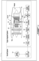
- another gas turbine engine 300 there is provided another gas turbine engine 300.
- the engine 300 can have similar architecture as in gas turbine engine 100.
- the description of common elements that have been described above are not repeated.
- the primary gas path 106 has, in fluid series communication, a primary air inlet 112, a compressor 104 fluidly connected to the primary air inlet 112 via an air conduit 370, a combustor 108 fluidly connected to an outlet 114 of the compressor 104, and a turbine 116 fluidly connected to an outlet 118 of the combustor 108, where the turbine 116 is operatively connected to the compressor 104 to drive the compressor 104.
- the turbine section includes a plurality of turbine stages and plurality of compressor stages. It is contemplated that the engine 300 can be a single compressor, single turbine engine, where there is a single stage of each of the compressor 104 and turbine 116.
- the engine 300 can include multiple stages of each of the compressor 104 and turbine 116, as shown, where there can be any number and type of stages.
- the compressor stages 140, 142 as shown are centrifugal, however there may be embodiments in which be one stage may be centrifugal followed by axial stages, embodiments may include all axial stages, for example. Any suitable number and combination of stages is contemplated herein.
- the combustor 108 is fluidly connected to the source of hydrogen 124 via the hydrogen conduit 139 defined in part by fluid conduits 128, 328 of upstream and downstream heat exchangers 122, 322.
- the pump 133 is operable to move hydrogen 119 from the source of hydrogen 124, through the upstream and downstream heat exchangers 122, 322, and ultimately to the combustor 108.
- the source of hydrogen 124 is a source of liquid hydrogen 119 operable to provide a supply of liquid hydrogen 119 to the fluid conduits 128, 328 of the upstream and downstream heat exchangers 122, 322.
- the pump 133 is a liquid hydrogen pump disposed in the hydrogen conduit 139 at a location that is fluidly upstream of the fluid conduits 128, 328 of the upstream and downstream heat exchangers 122,322.
- the pump 133 can be driven by a power source 178 operatively connected to the pump 133.
- the fluid conduit 128 of the upstream heat exchanger 122 is in fluid isolation from an air conduit 126 of upstream first heat exchanger 122 and in thermal communication with the air conduit 126.
- the fluid conduit 128 extends from the hydrogen inlet 130 to a hydrogen outlet 138, the hydrogen inlet 130 being fluidly connected to the source of hydrogen 124 and the hydrogen outlet 138 being fluidly connected to the fluid conduit 328.
- the fluid conduit 328 of the downstream heat exchanger 322 is in fluid isolation from an air conduit 326 of the downstream heat exchanger 322 and in thermal communication with the air conduit 326.
- the fluid conduit 328 extends from the hydrogen inlet 130 to a hydrogen outlet 338 (e.g. the fluid conduit 328 of the downstream heat exchanger 322 is fluidly connected to the source of hydrogen 124 via the fluid conduit 128 of the upstream heat exchanger 122).
- the flow of hydrogen will be described as it is moved from the source of hydrogen 124 to the combustor 108.
- the liquid hydrogen is moved through the hydrogen pump 133 to the fluid conduit 128 of the upstream heat exchanger 122 where it is first expanded to gaseous hydrogen 121.
- the gaseous hydrogen 121 is moved through to the fluid conduit 328 of the downstream heat exchanger 322 where it is further expanded, and then moved through conduit 139 to the expansion turbine 134.
- the gaseous hydrogen 121 drives rotation of the expansion turbine 134, and is then moved through the conduit 139 to the accumulator 156, where it is held in the accumulator 156 until its commanded release (e.g. via controller 160) to the combustor 108.
- the hydrogen 119, 121 is expanded in the upstream and downstream heat exchangers 122, 322 through thermal communication with hot compressor air in the air conduit 370, as described below.
- the upstream and downstream heat exchangers 122, 322 and the liquid hydrogen pump 133 are sized to convert a majority of the supply of liquid hydrogen 119 into a supply of gaseous hydrogen 121.
- the upstream and downstream heat exchangers 122, 322 and the liquid hydrogen pump 133 are sized to convert 90%-100% of the supply of liquid hydrogen 119 into a supply of gaseous hydrogen 121, by volume.
- the supply rate (e.g. flow rate) of the pump 133, and the heat transfer rates of the heat exchangers 122, 322 are selected for the particular application and size of engine such that the claimed functionality is provided, where the sizing and/or selection of pump and heat exchanger may be done using conventional engineering principles, for example.
- the hydrogen conduit 139 is defined in part by the expansion turbine 134 at a location in the hydrogen conduit 139 that is fluidly downstream of the fluid conduits 128, 328 of the upstream and downstream heat exchangers 122, 322.
- the hydrogen conduit 139 is defined in part by the gaseous hydrogen accumulator 156 at a location in the hydrogen conduit 139 that is fluidly downstream of the fluid conduits 128, 328 of the upstream and downstream heat exchangers 122, 322 and downstream of the expansion turbine 134.
- the primary air inlet 112 of the air conduit 370 is connected in fluid communication with the primary gas path 106 fluidly downstream of at least one compressor stage of the compressor 104 and upstream of the combustor 108.
- the air outlet 114 is connected to the turbine section 116 for cooling in the turbine section 116 using air from the compressor 104 conveyed through a turbine cooling air conduit 372.
- the air passes through the first compressor stage 140, the air is heated, before passing through the air conduit 126 of the upstream heat exchanger 122.
- This hot compressor air heats the liquid hydrogen 119 in the upstream heat exchanger 122, expanding the hydrogen a given amount. This given amount may be sufficient to power the expansion turbine 134 and may be sufficient for combustion, however, there is still potential for additional expansion.
- turbine cooling air conduit 372 extends from an air inlet 374 of the turbine cooling air conduit to an air outlet 376 of the turbine cooling air conduit 372.
- the outlet 376 can be the same as compressor outlet 114, or a different outlet than outlet 114.
- the turbine cooling air conduit 372 is defined in part by the air conduit 326 of the first heat exchanger 322 and the air conduit 370 of the primary gas path 106 is therefore defined in part by the air conduit 126 of the second heat exchanger 122 at a location in the primary gas path that is between adjacent compressor stages of the plurality of compressor stages 140, 142.
- the air inlet 374 of the turbine cooling air conduit 372 is fluidly downstream of all compressor stages 140, 142.
- a method of operating the engine 300 in the aircraft includes heating the flow of gaseous hydrogen 121 in an upstream heat exchanger 122 with compressor discharge air, passing a flow of gaseous hydrogen 121 through a compressor 104 to a downstream heat exchanger 322, downstream of the upstream heat exchanger 122, extracting kinetic energy from the flow of gaseous hydrogen 121 from the downstream heat exchanger 322 to rotate a rotatable component 120 of the aircraft 1.
- the method further includes, expanding a flow of liquid hydrogen 119 to a flow of gaseous hydrogen 121 in the upstream heat exchanger 122 upstream of the downstream heat exchanger 322 relative to hydrogen flow, compressing cooled air from the second heat exchanger 122, where expanding the liquid hydrogen 119 to gaseous hydrogen 121 includes cooling the compressed air from a first compressor stage 140, and supplying heat to the downstream heat exchanger 322 with compressed air from a second compressor stage 142.
- the method further include using rotation of the rotatable component 120, generating one or both of: thrust, and electrical power.
Landscapes
- Engineering & Computer Science (AREA)
- Chemical & Material Sciences (AREA)
- Combustion & Propulsion (AREA)
- Mechanical Engineering (AREA)
- General Engineering & Computer Science (AREA)
- Physics & Mathematics (AREA)
- Fluid Mechanics (AREA)
- Engine Equipment That Uses Special Cycles (AREA)
- Aviation & Aerospace Engineering (AREA)
- Structures Of Non-Positive Displacement Pumps (AREA)
Claims (14)
- Moteur à turbine à gaz (300), comprenant :un trajet de gaz primaire (106) comportant, en communication fluidique en série : une entrée d'air primaire (112), un compresseur (104) relié fluidiquement à l'entrée d'air primaire (112), une chambre de combustion (108) reliée fluidiquement à une sortie (114) du compresseur (104), et une turbine (116) reliée fluidiquement à une sortie (118) de la chambre de combustion (108), la turbine (116) étant reliée fonctionnellement au compresseur (104) pour entraîner le compresseur (104) ; etun conduit d'air de refroidissement de turbine (372) se prolongeant à partir d'une entrée d'air (374) du conduit d'air de refroidissement de turbine (372) à une sortie d'air (376) du conduit d'air de refroidissement de turbine (372),l'entrée d'air en amont (374) reliée en communication fluidique au trajet de gaz primaire (106) à un emplacement en aval du compresseur (104) et en amont d'une chambre de combustion de la chambre de combustion (108),la sortie d'air (376) reliée à la turbine (116) pour le refroidissement de la turbine (116) à l'aide de l'air provenant du compresseur (104) transporté à travers le trajet d'air de refroidissement de turbine (372) ; etdans lequel le conduit d'air de refroidissement de turbine (372) est défini en partie par un conduit d'air (326) d'un échangeur de chaleur (322), l'échangeur de chaleur (322) comportant un conduit de fluide (328) en isolation fluidique à partir du conduit d'air (326) et en communication thermique avec le conduit d'air (326), le conduit de fluide (328) se prolongeant à partir d'une entrée d'hydrogène (130) du conduit de fluide (328) à une sortie d'hydrogène (338) du conduit de fluide (328), l'entrée d'hydrogène (130) étant reliée fluidiquement à une source d'hydrogène (124), la sortie d'hydrogène (338) étant reliée fluidiquement à la chambre de combustion (108),caractérisé en ce que :l'échangeur de chaleur (322) est un échangeur de chaleur en aval (322) et le trajet de gaz primaire (106) est défini en partie par un conduit d'air (126) d'un échangeur de chaleur en amont (122) à un emplacement dans le trajet de gaz primaire (106) qui se trouve entre des étages de compresseur adjacents de la pluralité d'étages de compresseur (140, 142), l'échangeur de chaleur en amont (122) comportant un conduit de fluide (128) en isolation fluidique à partir du conduit d'air (126) de l'échangeur de chaleur en amont (122) et en communication thermique avec le conduit d'air (126) de l'échangeur de chaleur en amont (122) ;le conduit de fluide (328) de l'échangeur de chaleur en aval (322) est relié fluidiquement à la source d'hydrogène (124) par le biais du conduit de fluide (128) de l'échangeur de chaleur en amont (122) ;la chambre de combustion (108) est reliée fluidiquement à la source d'hydrogène (124) par le biais d'un conduit d'hydrogène (139) défini en partie par les conduits de fluide (128, 328) des échangeurs de chaleur en amont et en aval (122, 322) et par une pompe (133) pouvant servir à déplacer l'hydrogène (119) de la source d'hydrogène (124) à la chambre de combustion (108) ; etle conduit d'hydrogène (139) est défini en partie par un accumulateur d'hydrogène gazeux (156) à un emplacement dans le conduit d'hydrogène (139) qui est fluidiquement en aval des conduits de fluide (128, 328) des échangeurs de chaleur en amont et en aval (122, 322).
- Moteur à turbine à gaz selon la revendication 1, comprenant une section de compresseur (102) reliée fluidiquement à l'entrée d'air primaire (112) et comportant une pluralité d'étages de compresseur (140, 142), et une section de turbine reliée fluidiquement à la sortie (118) de la chambre de combustion (108) et reliée fonctionnellement à la section de compresseur (102) pour entraîner la section de compresseur (102), la section de turbine comportant une pluralité d'étages de turbine, et dans lequel :le compresseur (104) est un étage de compresseur de la pluralité d'étages de compresseur (140, 142),la turbine (116) est un étage de turbine de la pluralité d'étages de turbine, etl'entrée d'air (374) du conduit d'air de refroidissement de turbine (372) est fluidiquement en aval d'au moins un étage de compresseur de la pluralité d'étages de compresseur (140, 142).
- Moteur selon la revendication 2, dans lequel l'entrée d'air (374) du conduit d'air de refroidissement de turbine (372) est fluidiquement en aval de tous les étages de compresseur (140, 142) de la pluralité d'étages de compresseur (140, 142).
- Moteur selon la revendication 2 ou 3, dans lequel la sortie d'air (376) du trajet d'air de refroidissement de turbine (372) est fluidiquement en amont de tous les étages de turbine de la pluralité d'étages de turbine.
- Moteur selon une quelconque revendication précédente, dans lequel :la source d'hydrogène (124) est une source d'hydrogène liquide (119) pouvant fonctionner pour fournir une alimentation en hydrogène liquide (119) au conduit de fluide (128) de l'échangeur de chaleur en amont (122) ; etla pompe (133) est une pompe à hydrogène liquide disposée dans le conduit d'hydrogène (139) à un emplacement qui est fluidiquement en amont du conduit de fluide (128) de l'échangeur de chaleur en amont (122).
- Moteur selon la revendication 5, dans lequel les échangeurs de chaleur en amont et en aval (122, 322) et la pompe à hydrogène liquide sont dimensionnés pour convertir une majorité de l'alimentation en hydrogène liquide (119) en une alimentation en hydrogène gazeux (121), ou dans lequel les échangeurs de chaleur en amont et en aval (122, 322) et la pompe à hydrogène liquide sont dimensionnés pour convertir 90% à 100% de l'alimentation en hydrogène liquide (119) en une alimentation en hydrogène gazeux (121), en volume.
- Moteur selon une quelconque revendication précédente, dans lequel le conduit d'hydrogène (139) est défini en partie par une turbine de détente (134) à un emplacement dans le conduit d'hydrogène (139) qui est fluidiquement en aval des conduits de fluide (128, 328) des échangeurs de chaleur en amont et en aval (122, 322).
- Moteur selon la revendication 7, dans lequel la turbine de détente (134) est reliée fonctionnellement à un composant rotatif (120, 148, 151) du moteur à turbine à gaz (300) pour entraîner le composant rotatif (120, 148, 151).
- Moteur selon la revendication 8, dans lequel le composant rotatif est l'un : d'un arbre de sortie (120, 151), d'une boîte de vitesses de réduction (148) et d'une boîte de vitesses d'accessoires (148).
- Moteur selon la revendication 8 ou 9, dans lequel le moteur à turbine à gaz (300) comprend une boîte de vitesses (148) ayant un arbre de sortie (151), un composant rotatif (146) de la turbine de détente (134) relié fonctionnellement à l'arbre de sortie (151) pour entraîner l'arbre de sortie (151) en parallèle avec la section de turbine, dans lequel la boîte de vitesses (148) est reliée fonctionnellement à un arbre principal (120) entraîné par la section de turbine, l'arbre de sortie (151) étant entraîné par la puissance combinée provenant de la section de turbine et de la turbine de détente (134).
- Moteur selon une quelconque revendication précédente, dans lequel l'accumulateur d'hydrogène gazeux (156) est fluidiquement en aval d'une ou de la turbine de détente (134) dans le conduit d'hydrogène (139).
- Procédé de fonctionnement du moteur (300) selon la revendication 1 dans un aéronef (1), comprenant :le chauffage d'un flux d'hydrogène gazeux (121) dans un échangeur de chaleur en amont (122) avec de l'air de refoulement de compresseur ;le passage du flux d'hydrogène gazeux (121) à travers le compresseur (104) à l'échangeur de chaleur (322), en aval de l'échangeur de chaleur en amont (122) ;l'extraction de l'énergie cinétique à partir du flux d'hydrogène gazeux (121) provenant de l'échangeur de chaleur en aval (322) pour faire tourner un composant rotatif (120, 148, 151) de l'aéronef (1) ; etaprès l'extraction, la combustion du flux d'hydrogène gazeux (121) avec l'air de refoulement du compresseur dans la chambre de combustion (108) du moteur à turbine à gaz (300) de l'aéronef (1) ; etle refroidissement de la turbine (116) du moteur à turbine à gaz (300) avec de l'air provenant de l'échangeur de chaleur en aval (322) .
- Procédé selon la revendication 12, comprenant également :la détente d'un flux d'hydrogène liquide (119) en un flux d'hydrogène gazeux (121) dans l'échangeur de chaleur en amont (122) en amont de l'échangeur de chaleur en aval (322) par rapport au flux d'hydrogène ;la compression de l'air refroidi provenant de l'échangeur de chaleur en amont (122) ;dans lequel la détente de l'hydrogène liquide (119) en hydrogène gazeux (121) comporte le refroidissement de l'air comprimé provenant d'un premier étage de compresseur (140) ; etl'alimentation en chaleur de l'échangeur de chaleur en aval (322) avec de l'air comprimé provenant d'un second étage de compresseur (142).
- Procédé selon la revendication 12 ou 13, comprenant également, à l'aide de la rotation du composant rotatif (120, 148, 151), la génération d'une ou des deux : d'une poussée et d'une énergie électrique.
Applications Claiming Priority (1)
| Application Number | Priority Date | Filing Date | Title |
|---|---|---|---|
| US17/383,120 US20230022809A1 (en) | 2021-07-22 | 2021-07-22 | Dual cycle intercooled engine architectures |
Publications (2)
| Publication Number | Publication Date |
|---|---|
| EP4123146A1 EP4123146A1 (fr) | 2023-01-25 |
| EP4123146B1 true EP4123146B1 (fr) | 2024-11-13 |
Family
ID=82701616
Family Applications (1)
| Application Number | Title | Priority Date | Filing Date |
|---|---|---|---|
| EP22186554.6A Active EP4123146B1 (fr) | 2021-07-22 | 2022-07-22 | Architectures de moteur refroidi à double cycle |
Country Status (6)
| Country | Link |
|---|---|
| US (1) | US20230022809A1 (fr) |
| EP (1) | EP4123146B1 (fr) |
| CN (1) | CN115680881A (fr) |
| BR (1) | BR102022014323A2 (fr) |
| CA (1) | CA3168539A1 (fr) |
| PL (1) | PL4123146T3 (fr) |
Families Citing this family (6)
| Publication number | Priority date | Publication date | Assignee | Title |
|---|---|---|---|---|
| US11927136B1 (en) * | 2021-06-04 | 2024-03-12 | Rtx Corporation | Turbofan engine with precooler |
| US12092032B1 (en) * | 2023-06-05 | 2024-09-17 | Honeywell International Inc. | Gas turbine engine hydrogen supply system and method |
| US12209535B2 (en) | 2023-06-16 | 2025-01-28 | Pratt & Whitney Canada Corp. | Turbine engine compressor intercooler |
| FR3162251B1 (fr) * | 2024-05-14 | 2026-04-24 | Safran Aircraft Engines | Systeme de carburant cryogenique a rechauffe regulee pour transitoires |
| CN120007440A (zh) * | 2024-10-08 | 2025-05-16 | 南京航空航天大学 | 一种基于涡扇发动机的氢能涡轮发动机架构 |
| CN119911427B (zh) * | 2025-02-24 | 2025-10-14 | 西北工业大学 | 一种叶轮机和电机一体化设计的混合动力涡扇发动机构型 |
Family Cites Families (11)
| Publication number | Priority date | Publication date | Assignee | Title |
|---|---|---|---|---|
| GB899312A (en) * | 1959-09-22 | 1962-06-20 | Napier & Son Ltd | Gas turbine engines |
| US5315819A (en) * | 1991-09-17 | 1994-05-31 | Allied-Signal Inc. | Power management system for turbine engines |
| EP2622192A2 (fr) * | 2010-09-30 | 2013-08-07 | General Electric Company | Systèmes de moteur d'avion et procédés de fonctionnement associés |
| BR112015015516A2 (pt) * | 2012-12-28 | 2017-07-11 | Gen Electric | conjunto de mecanismo motor de turbina |
| GB2531775B (en) * | 2014-10-30 | 2018-05-09 | Rolls Royce Plc | A gas turbine using cryogenic fuel passed through a fuel turbine |
| FR3074255B1 (fr) * | 2017-11-24 | 2021-06-04 | Engie | Dispositif et procede autonome de fourniture d'electricite |
| US11725584B2 (en) * | 2018-01-17 | 2023-08-15 | General Electric Company | Heat engine with heat exchanger |
| US20190292986A1 (en) * | 2018-03-20 | 2019-09-26 | Panasonic Intellectual Property Management Co., Ltd. | Gas turbine system |
| US11047307B2 (en) * | 2018-09-14 | 2021-06-29 | Raytheon Technologies Corporation | Hybrid expander cycle with intercooling and turbo-generator |
| US11066999B2 (en) * | 2019-01-16 | 2021-07-20 | Raytheon Technologies Corporation | Fuel cooled cooling air |
| US11674443B2 (en) * | 2020-11-06 | 2023-06-13 | General Electric Company | Hydrogen fuel system |
-
2021
- 2021-07-22 US US17/383,120 patent/US20230022809A1/en not_active Abandoned
-
2022
- 2022-07-20 BR BR102022014323-4A patent/BR102022014323A2/pt unknown
- 2022-07-21 CA CA3168539A patent/CA3168539A1/fr active Pending
- 2022-07-22 CN CN202210869896.1A patent/CN115680881A/zh active Pending
- 2022-07-22 EP EP22186554.6A patent/EP4123146B1/fr active Active
- 2022-07-22 PL PL22186554.6T patent/PL4123146T3/pl unknown
Also Published As
| Publication number | Publication date |
|---|---|
| BR102022014323A2 (pt) | 2023-03-07 |
| CA3168539A1 (fr) | 2023-01-22 |
| US20230022809A1 (en) | 2023-01-26 |
| EP4123146A1 (fr) | 2023-01-25 |
| PL4123146T3 (pl) | 2025-03-03 |
| CN115680881A (zh) | 2023-02-03 |
Similar Documents
| Publication | Publication Date | Title |
|---|---|---|
| EP4095369B1 (fr) | Architecture du moteur refroidi à l'hydrogène à double cycle | |
| EP4123146B1 (fr) | Architectures de moteur refroidi à double cycle | |
| EP3623604B1 (fr) | Cycle d'expansion hybride avec refroidissement pré-compression et turbogénérateur | |
| EP3623602B1 (fr) | Cycle d'expansion hybride à refroidissement intermédiaire et turbo-générateur | |
| US11753993B1 (en) | Turbine engine with mass rejection | |
| EP3623603B1 (fr) | Cycle d'expanseur hybride comportant un turbo-générateur et une électronique de puissance refroidie | |
| US20250198330A1 (en) | Hydrogen turbine power assisted condensation | |
| US12270341B2 (en) | Gas turbine engine fuel system | |
| US20240167427A1 (en) | Inter-cooled preheat of steam injected turbine engine | |
| EP4279718B1 (fr) | Conduit de condenseur de moteur à turbine alimenté en hydrogène | |
| US12078104B2 (en) | Hydrogen steam injected and inter-cooled turbine engine | |
| EP4520934A1 (fr) | Condensation partielle des gaz d'échappement avec contrôle de brayton inverse | |
| RU2376483C1 (ru) | Атомный газотурбинный двигатель с форсажем | |
| RU2379532C1 (ru) | Атомный газотурбинный авиационный двигатель | |
| EP4361420B1 (fr) | Moteur à turbine à gaz combiné et pile à combustible | |
| US12601486B2 (en) | Hydrogen fuelled gas turbine engine | |
| RU2349775C1 (ru) | Атомный газотурбинный авиационный двигатель | |
| RU2336429C1 (ru) | Атомный газотурбинный двигатель |
Legal Events
| Date | Code | Title | Description |
|---|---|---|---|
| PUAI | Public reference made under article 153(3) epc to a published international application that has entered the european phase |
Free format text: ORIGINAL CODE: 0009012 |
|
| STAA | Information on the status of an ep patent application or granted ep patent |
Free format text: STATUS: THE APPLICATION HAS BEEN PUBLISHED |
|
| AK | Designated contracting states |
Kind code of ref document: A1 Designated state(s): AL AT BE BG CH CY CZ DE DK EE ES FI FR GB GR HR HU IE IS IT LI LT LU LV MC MK MT NL NO PL PT RO RS SE SI SK SM TR |
|
| STAA | Information on the status of an ep patent application or granted ep patent |
Free format text: STATUS: REQUEST FOR EXAMINATION WAS MADE |
|
| 17P | Request for examination filed |
Effective date: 20230725 |
|
| RBV | Designated contracting states (corrected) |
Designated state(s): AL AT BE BG CH CY CZ DE DK EE ES FI FR GB GR HR HU IE IS IT LI LT LU LV MC MK MT NL NO PL PT RO RS SE SI SK SM TR |
|
| GRAP | Despatch of communication of intention to grant a patent |
Free format text: ORIGINAL CODE: EPIDOSNIGR1 |
|
| STAA | Information on the status of an ep patent application or granted ep patent |
Free format text: STATUS: GRANT OF PATENT IS INTENDED |
|
| INTG | Intention to grant announced |
Effective date: 20240607 |
|
| GRAS | Grant fee paid |
Free format text: ORIGINAL CODE: EPIDOSNIGR3 |
|
| GRAA | (expected) grant |
Free format text: ORIGINAL CODE: 0009210 |
|
| STAA | Information on the status of an ep patent application or granted ep patent |
Free format text: STATUS: THE PATENT HAS BEEN GRANTED |
|
| AK | Designated contracting states |
Kind code of ref document: B1 Designated state(s): AL AT BE BG CH CY CZ DE DK EE ES FI FR GB GR HR HU IE IS IT LI LT LU LV MC MK MT NL NO PL PT RO RS SE SI SK SM TR |
|
| REG | Reference to a national code |
Ref country code: GB Ref legal event code: FG4D |
|
| REG | Reference to a national code |
Ref country code: CH Ref legal event code: EP |
|
| REG | Reference to a national code |
Ref country code: IE Ref legal event code: FG4D |
|
| REG | Reference to a national code |
Ref country code: DE Ref legal event code: R096 Ref document number: 602022007645 Country of ref document: DE |
|
| REG | Reference to a national code |
Ref country code: LT Ref legal event code: MG9D |
|
| REG | Reference to a national code |
Ref country code: NL Ref legal event code: MP Effective date: 20241113 |
|
| PG25 | Lapsed in a contracting state [announced via postgrant information from national office to epo] |
Ref country code: PT Free format text: LAPSE BECAUSE OF FAILURE TO SUBMIT A TRANSLATION OF THE DESCRIPTION OR TO PAY THE FEE WITHIN THE PRESCRIBED TIME-LIMIT Effective date: 20250313 Ref country code: IS Free format text: LAPSE BECAUSE OF FAILURE TO SUBMIT A TRANSLATION OF THE DESCRIPTION OR TO PAY THE FEE WITHIN THE PRESCRIBED TIME-LIMIT Effective date: 20250313 Ref country code: HR Free format text: LAPSE BECAUSE OF FAILURE TO SUBMIT A TRANSLATION OF THE DESCRIPTION OR TO PAY THE FEE WITHIN THE PRESCRIBED TIME-LIMIT Effective date: 20241113 |
|
| PG25 | Lapsed in a contracting state [announced via postgrant information from national office to epo] |
Ref country code: FI Free format text: LAPSE BECAUSE OF FAILURE TO SUBMIT A TRANSLATION OF THE DESCRIPTION OR TO PAY THE FEE WITHIN THE PRESCRIBED TIME-LIMIT Effective date: 20241113 Ref country code: NL Free format text: LAPSE BECAUSE OF FAILURE TO SUBMIT A TRANSLATION OF THE DESCRIPTION OR TO PAY THE FEE WITHIN THE PRESCRIBED TIME-LIMIT Effective date: 20241113 |
|
| REG | Reference to a national code |
Ref country code: AT Ref legal event code: MK05 Ref document number: 1741842 Country of ref document: AT Kind code of ref document: T Effective date: 20241113 |
|
| PG25 | Lapsed in a contracting state [announced via postgrant information from national office to epo] |
Ref country code: BG Free format text: LAPSE BECAUSE OF FAILURE TO SUBMIT A TRANSLATION OF THE DESCRIPTION OR TO PAY THE FEE WITHIN THE PRESCRIBED TIME-LIMIT Effective date: 20241113 |
|
| PG25 | Lapsed in a contracting state [announced via postgrant information from national office to epo] |
Ref country code: ES Free format text: LAPSE BECAUSE OF FAILURE TO SUBMIT A TRANSLATION OF THE DESCRIPTION OR TO PAY THE FEE WITHIN THE PRESCRIBED TIME-LIMIT Effective date: 20241113 |
|
| PG25 | Lapsed in a contracting state [announced via postgrant information from national office to epo] |
Ref country code: NO Free format text: LAPSE BECAUSE OF FAILURE TO SUBMIT A TRANSLATION OF THE DESCRIPTION OR TO PAY THE FEE WITHIN THE PRESCRIBED TIME-LIMIT Effective date: 20250213 |
|
| PG25 | Lapsed in a contracting state [announced via postgrant information from national office to epo] |
Ref country code: LV Free format text: LAPSE BECAUSE OF FAILURE TO SUBMIT A TRANSLATION OF THE DESCRIPTION OR TO PAY THE FEE WITHIN THE PRESCRIBED TIME-LIMIT Effective date: 20241113 Ref country code: AT Free format text: LAPSE BECAUSE OF FAILURE TO SUBMIT A TRANSLATION OF THE DESCRIPTION OR TO PAY THE FEE WITHIN THE PRESCRIBED TIME-LIMIT Effective date: 20241113 Ref country code: GR Free format text: LAPSE BECAUSE OF FAILURE TO SUBMIT A TRANSLATION OF THE DESCRIPTION OR TO PAY THE FEE WITHIN THE PRESCRIBED TIME-LIMIT Effective date: 20250214 |
|
| PG25 | Lapsed in a contracting state [announced via postgrant information from national office to epo] |
Ref country code: RS Free format text: LAPSE BECAUSE OF FAILURE TO SUBMIT A TRANSLATION OF THE DESCRIPTION OR TO PAY THE FEE WITHIN THE PRESCRIBED TIME-LIMIT Effective date: 20250213 |
|
| PG25 | Lapsed in a contracting state [announced via postgrant information from national office to epo] |
Ref country code: SM Free format text: LAPSE BECAUSE OF FAILURE TO SUBMIT A TRANSLATION OF THE DESCRIPTION OR TO PAY THE FEE WITHIN THE PRESCRIBED TIME-LIMIT Effective date: 20241113 |
|
| PG25 | Lapsed in a contracting state [announced via postgrant information from national office to epo] |
Ref country code: DK Free format text: LAPSE BECAUSE OF FAILURE TO SUBMIT A TRANSLATION OF THE DESCRIPTION OR TO PAY THE FEE WITHIN THE PRESCRIBED TIME-LIMIT Effective date: 20241113 |
|
| PG25 | Lapsed in a contracting state [announced via postgrant information from national office to epo] |
Ref country code: EE Free format text: LAPSE BECAUSE OF FAILURE TO SUBMIT A TRANSLATION OF THE DESCRIPTION OR TO PAY THE FEE WITHIN THE PRESCRIBED TIME-LIMIT Effective date: 20241113 |
|
| PGFP | Annual fee paid to national office [announced via postgrant information from national office to epo] |
Ref country code: FR Payment date: 20250619 Year of fee payment: 4 |
|
| PG25 | Lapsed in a contracting state [announced via postgrant information from national office to epo] |
Ref country code: RO Free format text: LAPSE BECAUSE OF FAILURE TO SUBMIT A TRANSLATION OF THE DESCRIPTION OR TO PAY THE FEE WITHIN THE PRESCRIBED TIME-LIMIT Effective date: 20241113 |
|
| PG25 | Lapsed in a contracting state [announced via postgrant information from national office to epo] |
Ref country code: SK Free format text: LAPSE BECAUSE OF FAILURE TO SUBMIT A TRANSLATION OF THE DESCRIPTION OR TO PAY THE FEE WITHIN THE PRESCRIBED TIME-LIMIT Effective date: 20241113 |
|
| PG25 | Lapsed in a contracting state [announced via postgrant information from national office to epo] |
Ref country code: IT Free format text: LAPSE BECAUSE OF FAILURE TO SUBMIT A TRANSLATION OF THE DESCRIPTION OR TO PAY THE FEE WITHIN THE PRESCRIBED TIME-LIMIT Effective date: 20241113 |
|
| REG | Reference to a national code |
Ref country code: DE Ref legal event code: R097 Ref document number: 602022007645 Country of ref document: DE |
|
| PG25 | Lapsed in a contracting state [announced via postgrant information from national office to epo] |
Ref country code: SE Free format text: LAPSE BECAUSE OF FAILURE TO SUBMIT A TRANSLATION OF THE DESCRIPTION OR TO PAY THE FEE WITHIN THE PRESCRIBED TIME-LIMIT Effective date: 20241113 |
|
| PLBE | No opposition filed within time limit |
Free format text: ORIGINAL CODE: 0009261 |
|
| STAA | Information on the status of an ep patent application or granted ep patent |
Free format text: STATUS: NO OPPOSITION FILED WITHIN TIME LIMIT |
|
| PGFP | Annual fee paid to national office [announced via postgrant information from national office to epo] |
Ref country code: DE Payment date: 20250620 Year of fee payment: 4 |
|
| PGFP | Annual fee paid to national office [announced via postgrant information from national office to epo] |
Ref country code: PL Payment date: 20250701 Year of fee payment: 4 |
|
| 26N | No opposition filed |
Effective date: 20250814 |
|
| PGFP | Annual fee paid to national office [announced via postgrant information from national office to epo] |
Ref country code: CZ Payment date: 20250630 Year of fee payment: 4 |
|
| REG | Reference to a national code |
Ref country code: CH Ref legal event code: H13 Free format text: ST27 STATUS EVENT CODE: U-0-0-H10-H13 (AS PROVIDED BY THE NATIONAL OFFICE) Effective date: 20260224 |
|
| PG25 | Lapsed in a contracting state [announced via postgrant information from national office to epo] |
Ref country code: LU Free format text: LAPSE BECAUSE OF NON-PAYMENT OF DUE FEES Effective date: 20250722 |
|
| REG | Reference to a national code |
Ref country code: BE Ref legal event code: MM Effective date: 20250731 |
|
| PG25 | Lapsed in a contracting state [announced via postgrant information from national office to epo] |
Ref country code: BE Free format text: LAPSE BECAUSE OF NON-PAYMENT OF DUE FEES Effective date: 20250731 |
|
| PG25 | Lapsed in a contracting state [announced via postgrant information from national office to epo] |
Ref country code: CH Free format text: LAPSE BECAUSE OF NON-PAYMENT OF DUE FEES Effective date: 20250731 |