EP4123152B1 - Ensemble de verrou d'un système inverseur de poussée et son procédé de fonctionnement - Google Patents
Ensemble de verrou d'un système inverseur de poussée et son procédé de fonctionnement Download PDFInfo
- Publication number
- EP4123152B1 EP4123152B1 EP22186081.0A EP22186081A EP4123152B1 EP 4123152 B1 EP4123152 B1 EP 4123152B1 EP 22186081 A EP22186081 A EP 22186081A EP 4123152 B1 EP4123152 B1 EP 4123152B1
- Authority
- EP
- European Patent Office
- Prior art keywords
- latch
- latch member
- axially extending
- rotatable arms
- extended position
- Prior art date
- Legal status (The legal status is an assumption and is not a legal conclusion. Google has not performed a legal analysis and makes no representation as to the accuracy of the status listed.)
- Active
Links
Images


Classifications
-
- F—MECHANICAL ENGINEERING; LIGHTING; HEATING; WEAPONS; BLASTING
- F02—COMBUSTION ENGINES; HOT-GAS OR COMBUSTION-PRODUCT ENGINE PLANTS
- F02K—JET-PROPULSION PLANTS
- F02K1/00—Plants characterised by the form or arrangement of the jet pipe or nozzle; Jet pipes or nozzles peculiar thereto
- F02K1/54—Nozzles having means for reversing jet thrust
- F02K1/76—Control or regulation of thrust reversers
- F02K1/766—Control or regulation of thrust reversers with blocking systems or locking devices; Arrangement of locking devices for thrust reversers
-
- B—PERFORMING OPERATIONS; TRANSPORTING
- B64—AIRCRAFT; AVIATION; COSMONAUTICS
- B64D—EQUIPMENT FOR FITTING IN OR TO AIRCRAFT; FLIGHT SUITS; PARACHUTES; ARRANGEMENT OR MOUNTING OF POWER PLANTS OR PROPULSION TRANSMISSIONS IN AIRCRAFT
- B64D29/00—Power-plant nacelles, fairings or cowlings
- B64D29/06—Attaching of nacelles, fairings or cowlings
-
- B—PERFORMING OPERATIONS; TRANSPORTING
- B64—AIRCRAFT; AVIATION; COSMONAUTICS
- B64D—EQUIPMENT FOR FITTING IN OR TO AIRCRAFT; FLIGHT SUITS; PARACHUTES; ARRANGEMENT OR MOUNTING OF POWER PLANTS OR PROPULSION TRANSMISSIONS IN AIRCRAFT
- B64D29/00—Power-plant nacelles, fairings or cowlings
- B64D29/08—Inspection panels for power plants
-
- F—MECHANICAL ENGINEERING; LIGHTING; HEATING; WEAPONS; BLASTING
- F05—INDEXING SCHEMES RELATING TO ENGINES OR PUMPS IN VARIOUS SUBCLASSES OF CLASSES F01-F04
- F05D—INDEXING SCHEME FOR ASPECTS RELATING TO NON-POSITIVE-DISPLACEMENT MACHINES OR ENGINES, GAS-TURBINES OR JET-PROPULSION PLANTS
- F05D2220/00—Application
- F05D2220/30—Application in turbines
- F05D2220/32—Application in turbines in gas turbines
- F05D2220/323—Application in turbines in gas turbines for aircraft propulsion, e.g. jet engines
-
- F—MECHANICAL ENGINEERING; LIGHTING; HEATING; WEAPONS; BLASTING
- F05—INDEXING SCHEMES RELATING TO ENGINES OR PUMPS IN VARIOUS SUBCLASSES OF CLASSES F01-F04
- F05D—INDEXING SCHEME FOR ASPECTS RELATING TO NON-POSITIVE-DISPLACEMENT MACHINES OR ENGINES, GAS-TURBINES OR JET-PROPULSION PLANTS
- F05D2260/00—Function
- F05D2260/30—Retaining components in desired mutual position
-
- Y—GENERAL TAGGING OF NEW TECHNOLOGICAL DEVELOPMENTS; GENERAL TAGGING OF CROSS-SECTIONAL TECHNOLOGIES SPANNING OVER SEVERAL SECTIONS OF THE IPC; TECHNICAL SUBJECTS COVERED BY FORMER USPC CROSS-REFERENCE ART COLLECTIONS [XRACs] AND DIGESTS
- Y10—TECHNICAL SUBJECTS COVERED BY FORMER USPC
- Y10T—TECHNICAL SUBJECTS COVERED BY FORMER US CLASSIFICATION
- Y10T292/00—Closure fasteners
- Y10T292/08—Bolts
- Y10T292/0886—Sliding and swinging
Definitions
- This disclosure relates generally to gas turbine engines, and more particularly to latch assemblies for gas turbine engine thrust reversers.
- Modern aircraft may include one or more propulsion systems powered by a gas turbine engine.
- the propulsion systems may include a nacelle which houses the engine and auxiliary systems, and which provides an aerodynamic surface for flight.
- the nacelle may also form a portion of a bypass air duct between the nacelle and the engine.
- the nacelle may include a thrust reverser (e.g., a cascade-type thrust reverser) which may include an inner fixed structure (“IFS").
- the IFS may form part of the interior surface of the bypass air duct through the thrust reverser and may define a core compartment that surrounds the engine.
- a thrust reverser IFS structure may be divided into panel halves which may be held together by remote latch assemblies. Bumpers may additionally be included between the panel halves to provide a load path for hoop compression experienced by the panel halves.
- the latch assemblies may have a pin-and-socket configuration in which a pin is engaged with an opposing socket in order to place the latch assembly in a latched condition.
- pin-and-socket type latch assemblies may be susceptible to jamming between the pin and associated socket, thereby causing difficulty in the unlatching of the latch assembly during maintenance of the associated gas turbine engine. Accordingly, there is a need for improved thrust reverser latch assemblies.
- US 2020/0102909 A1 discloses a prior art latch assembly for a gas turbine engine thrust reverser system as set forth in the preamble of claim 1.
- EP 1 764 499 A1 discloses a further latch assembly.
- a latch assembly for a gas turbine engine thrust reverser system as recited in claim 1.
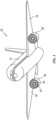
- FIG. 1 a perspective view of an aircraft 10 is shown in FIG. 1 .
- the aircraft 10 includes a fuselage 12 and wings 14 which extend outwardly from the fuselage 12.
- the aircraft 10 may include one or more propulsion systems which may be supported, for example, by the wings 14 of the aircraft 10.
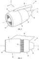
- the propulsion systems may include a gas turbine engine such as the gas turbine engine 20 illustrated in FIGS. 1-3 .
- the gas turbine engine 20 includes a fan 22 and an engine core 24 housed within a nacelle 26 and disposed about an axial centerline 27.
- the nacelle 26 is mounted to a pylon 28 which may, for example, mount the gas turbine engine 20 to the wing 14 of the aircraft 10.
- the nacelle 26 may include an inlet 30, a fan cowl 32, a thrust reverser system 34, and an exhaust system 36.
- the nacelle surrounds the engine core 24 providing smooth aerodynamic surfaces for airflow around and into the gas turbine engine 20.
- the nacelle 26 also defines a portion of a bypass air duct through the gas turbine engine 20.
- the fan 22 may draw and direct a flow of air into and through the gas turbine engine 20.
- the air is divided into two principal flow paths, one flow path through engine core 24 (i.e., a "core airflow"), and another flow path through a bypass air duct (i.e., a "bypass airflow").
- the engine core flow path is directed into the engine core 24 and initially passes through a compressor that increases the air flow pressure, and then through a combustor where the air is mixed with fuel and ignited.
- the combustion of the fuel and air mixture causes a series of turbine blades at the rear of the engine core 24 to rotate, and to drive the engine's compressor and fan 22.
- the high-pressure exhaust gases from the combustion of the fuel and air mixture are thereafter directed through the exhaust system 36 for thrust.
- the thrust reverser system 34 may include an inner fixed structure 38 ("IPS") and a translating sleeve 40.
- the translating sleeve 40 in combination with an air diversion system (e.g., blocker doors, diversion doors, etc. - not shown) may be configured to direct airflow in the bypass duct through one or more cascade arrays 42 to create reverse thrust.
- the translating sleeve 40 may translate and/or move from a forward position (see FIG. 2 ) to an aft position (see FIG. 3 ), thereby separating the translating sleeve 40 from the fan cowl 32.
- the aft movement of the translating sleeve 40 and operation of the air diversion system causes air to be diverted from the bypass duct through the cascade arrays 38 and in a forward direction to create reverse thrust.
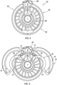
- FIGS. 4 and 5 an aft view of the thrust reverser system 34 in a closed condition is shown in FIG. 4 while an aft view of the thrust reverser system 34 in an open condition is shown in FIG. 5 .
- the thrust reverser system 34 may be split into halves, for example, a left outer panel half 44 and counterpart right outer panel half 46 of the translating sleeve 40 and a left inner panel half 48 and counterpart right inner panel half 50 of the inner fixed structure 38.
- the outer panel halves 44, 46 and the inner panel halves 48, 50 may be hinged to the pylon 28 at hinges 52 and may be hinged open in order to provide access to interior portions of the gas turbine engine 20 such as the engine core 24.
- the term "closed condition” will be used to refer to the panel halves 44, 46, 48, 50 in a fully shut position (e.g., the panel halves 44, 46, 48, 50 are positioned for flight).
- the term "open condition” will be used to refer to the panel halves 44, 46, 48, 50 in a condition other than the closed condition (e.g., the panel halves 44, 46, 48, 50 are partially open, fully open, etc.).
- the inner fixed structure 38 of the thrust reverser system 34 includes one or more remotely actuated latch assemblies 54 configured to secure the left inner panel half 48 and the right inner panel half 50 (hereinafter the "first panel half” 48 and the “second panel half” 50) together in a closed condition.
- the latch assembly 54 may be operated by an actuation system (not shown), however, the present disclosure is not limited to any particular actuation system or means for operating the latch assembly 54.
- FIGS. 6 and 7 illustrate the configuration of the latch assembly 54 with respect to a latch axis 56, with the first panel half 48 and the second panel half 50 in a closed condition.
- the latch assembly 54 includes a housing 58.
- the housing 58 includes a first housing portion 60 mounted to the first panel half 48 and a second housing portion 62 mounted to the second panel half 50.
- the first housing portion 60 may include a lateral wall 64 having an exterior surface 66 which faces the second housing portion 62 with the panel halves 48, 50 in a closed condition, and an interior surface 68 opposite the exterior surface 66.
- the first housing portion 60 may further include an aperture 70 extending along the latch axis 56 from the interior surface 68 to the exterior surface 66.
- the second housing portion 62 may include a lateral wall 72 having an exterior surface 74 which faces the first housing portion 60 with the panel halves 48, 50 in a closed condition, and an interior surface 76 opposite the exterior surface 74.
- the second housing portion 62 may further include an aperture 78 extending along the latch axis 56 from the interior surface 76 to the exterior surface 74.
- the second housing portion 62 has an interior width 80 substantially perpendicular to the latch axis 56.
- the aperture 78 has an aperture width 82 substantially perpendicular to the latch axis 56.
- the latch assembly 54 includes a first latch member 84 disposed within the first housing portion 60.
- the first latch member 84 is configured to translate or otherwise move along the latch axis 56 between a retracted position (see FIG. 6 ) and an extended position (see FIG. 7 ).
- the first latch member 84 includes a body 86 having a first end 88 and a second end 90 opposite the first end 88.
- the body 86 includes an axially extending passage 92 extending through all or at least a portion of the body 86 from the second end 90 toward the first end 88.
- the first latch member 84 includes at least two rotatable arms 94.
- Each of the rotatable arms 94 is rotatably attached to the body 86 at respective rotation joints 96.
- the rotatable arms 94 are configured to rotate about the respective rotation joints 96, located radially outside of the passage 92, between a retracted position (see FIG. 6 ) and an extended position (see FIG. 7 ).
- the rotatable arms 94 In the retracted position, the rotatable arms 94 are positioned within the body 86, for example, within a recess 98 of the body 86, or are otherwise positioned to extend along the body 86.
- the rotatable arms 94 extend outward from the body 86 in a direction away from the latch axis 56.
- the rotatable arms 94 may extend in a direction substantially perpendicular to the latch axis 56.
- the first latch member 84 including the rotatable arms 94, has a minimum width 100 substantially perpendicular to the latch axis 56.
- the minimum width 100 may be less than the aperture width 82.
- the rotatable arms 94, and hence the first latch member 84 has a maximum width 102 substantially perpendicular to the latch axis 56.
- the maximum width 102 may be greater than the aperture width 82 but less than the interior width 80.
- the rotatable arms 94 may radially overlap the interior surface 76 of the lateral wall 72.
- the body 86 has a length 103 extending from the rotatable arms 94 to the first end 88 substantially parallel to the latch axis 56.
- the first latch member 84 may include an actuation rod 104 configured to rotate the rotatable arms 94 between the retracted and extended positions.
- the actuation rod 104 may be disposed within the passage 92 and extend outward from the body 86 at the second end 90.
- the actuation rod 104 may be configured to translate or otherwise move along the latch axis 56 within the passage 92. Accordingly, the actuation rod 104 may be translated (e.g., axially translated) to rotate the rotatable arms 94 from the retracted position to the extended position or from the extended position to the retracted position.
- the actuation rod 104 may be connected to each of the rotatable arms 94 by at least one connector 106 rotatably mounted to the actuating rod 104 at a first connector end 108 and rotatably mounted to each respective rotatable arm 94 at a second connector end 110.
- the present disclosure is not limited to the above-described configuration of the actuation rod 104 to rotate the rotatable arms 94 between the retracted and extended positions, and operation of the rotatable arms 94 may be effected by other means.
- the latch assembly 54 includes a second latch member 112 disposed within the second housing portion 62.
- the second latch member 112 is configured to translate or otherwise move along the latch axis 56 between a retracted position (see FIG. 6 ) and an extended position (see FIG. 7 ).
- the second latch member 112 includes a body 114 having a first end 116 and a second end 118 opposite the first end 116.
- the body 114 includes a base portion 120 and at least one axially extending portion 122 extending from the base portion 120 toward the interior surface 76 of the lateral wall 72.
- the at least one axially extending portion 122 radially surrounds and defines a recess 124 located along the latch axis 56.
- the at least one axially extending portion 122 may include at least two axially extending portions with each of the at least two axially extending portions being circumferentially aligned with a respective rotatable arm of the rotatable arms 94.
- the recess 124 of the second latch member 112 has a recess width 128 substantially perpendicular to the latch axis 56.
- the recess width 128 may be greater than the aperture width 82 and the minimum width 100.
- the recess width 128 may be less than the maximum width 102.
- the recess 124 of the second latch member 112 also has a recess depth 130 between the first end 116 and the base portion 120, which may be substantially parallel to the latch axis 56.
- the recess depth 130 may be greater than the length 103.
- the body 114 includes an axially extending passage 126 extending through a portion of the body 114 from the second end 118 of the body 114 toward the first end 116 of the body 114.
- the passage 126 may include a first passage segment 138 extending from the second end 118 and a second passage segment 140 extending from the first passage segment 138 toward the first end 116.
- the second passage segment 140 may have a diameter 142 that is greater than a diameter 144 of the first passage segment 138.
- the second passage segment 140 may extend from a first axial segment end 146 to a second axial segment end 148 at the location where the second passage segment 140 meets the first passage segment 138.
- the second latch member 112 may include a locking pin 150.
- the locking pin 150 may be disposed within the passage 126 and extend outward from the body 114 at the second end 118.
- the locking pin 150 may be configured to translate or otherwise move along the latch axis 56 within the passage 126.
- the locking pin 150 may include a locking member 152 located at a distal end of the locking pin 150 and retained within the second passage segment 140.
- the locking member 152 may have a size and/or shape to prevent the locking member 152 from being withdrawn into the first passage segment 138.
- the second latch member 112 may include an axially extending spring 132 disposed within the second passage segment 140.
- the spring 132 has a first axial end 134 and a second axial end 136 opposite the first axial end 134.
- the first axial end 134 of the spring 132 is disposed proximate and may contact the body 114 of the second latch member 112 at the first axial segment end 146.
- the second axial end 136 of the spring 132 is disposed proximate and may contact the locking member 152 of the locking pin 150.
- the spring 132 may be configured for compression between the body 114 and the locking pin 150 and may axially bias the body 114 of the second latch member 112 in a direction away from the locking pin 150.
- the second latch member 112 may include a pin stopper 154 extending radially inward from the body 114 into the second passage segment 140.
- the pin stopper 154 may be in integral portion of the body 114 or may be a distinct component separately installed into the second passage segment 140.
- the pin stopper 154 may be located axially between first segment end 146 and the second segment end 148 of the second passage segment 140.
- the pin stopper 154 may extend around all or a portion of the interior circumference of the second passage segment 140.
- the pin stopper 154 may project radially inward into the second passage segment 140 a distance sufficient to obstruct axial movement of the locking member 152 but may not substantially impact axial compression or expansion of the spring 132.
- the pin stopper 154 may be configured to allow the locking member 152 to pass axially through the pin stopper 154, for example, through twisting engagement of the locking member 152 with the pin stopper 154.
- the present disclosure is not limited to inclusion of the above-described configuration of the passage 126, spring 132, locking pin 150, and/or pin stopper 154.
- first housing portion 60 and associated first latch member 84 are described herein as being associated with the first panel half 48 and the second housing portion 62 and associated second latch member 112 are described herein as being associated with the second panel half 50, it should be understood that the latch assembly 54 components of the present disclosure are limited to this particular configuration.
- the term "substantially" with regard to an angular relationship refers to the noted angular relationship +/- 10 degrees.
- the present disclosure includes a method 1000 for operating a latch assembly, such as the latch assembly 54.
- the latch assembly 54 may initially be in an "unlatched condition" with each of the first latch member 84, the rotatable arms 94, and the second latch member 112 in their respective retracted positions as shown, for example, in FIG. 8A .
- the first and second panel halves 48, 50 may be in a closed condition so that the first housing portion 60 is positioned adjacent the second housing portion 62 along the latch axis 56.
- the method 1000 includes translating the first latch member 84 along the latch axis 56 from the retracted position to the extended position (see FIGS. 9A and 9B ).
- the first latch member 84 may extend through the apertures 70, 78 of the respective first housing portion 60 and second housing portion 62.
- the rotatable arms 94 may be located axially within the second housing portion 62.
- the method 1000 includes rotating the rotatable arms 94 from the retracted position to the extended position (see FIGS. 9B and 9C ).
- the rotatable arms 94 may be rotated from the retracted position to the extended position by operation of the actuation rod 104. Insertion of the actuation rod 104 into the body 86 causes the connectors 106 about the respective first connector end 108 and second connector end 110, thereby causing the rotatable arms 94 to rotate in a counterclockwise direction from the retracted position to the extended position.
- the method 1000 includes translating the second latch member 112 along the latch axis 56 from the retracted position to the extended position (see FIGS. 9C and 9D ).
- the second latch member 112 may be axially spaced from the rotatable arms 94 of the first latch member 84.
- the first latch member 84 and the rotatable arms 94 in their respective extended positions, translation of the second latch member 112 from the retracted position to the extended position will cause the axially extending portions 122 of the second latch member 112 to contact the rotatable arms 94 of the first latch member 84.
- the rotatable arms 94 may be in contact with and fixed between the axially extending portions 122 of the second latch member 112 and the interior surface 76 of the lateral wall 72 of the second housing portion 62, as shown in FIG. 9D .
- continued axial translation of the second latch member 112 toward the first latch member 84 may cause compression of the spring 132 between the body 114 and the locking pin 150.
- Axial force from the compression of the spring 132 may aid in establishing a desired preload between the first and second latch members 84, 112.
- the latch assembly 54 of the present disclosure effects latching, in part, by locking abutting surfaces (e.g., fixing the rotatable arms 94 between the second housing portion 62 and the second latch member 112), and thereby substantially reduces or eliminates the likelihood of jamming in comparison to conventional thrust reverser pin-and-socket latch assemblies of which we are aware.
- the configuration of the latch members 84, 112 for translation and abutment along the latch axis 56 allows the latch assembly 54 to effectively resist both tension loads and compressive loads on the panel halves 48, 50 during operation of the gas turbine engine 20.
- the method 1000 may additionally include "locking" the axial position of the second latch member 112.
- the axial position of the second latch member 112 may be locked by, for example, engaging the locking pin 150 with the pin stopper 154.
- the locking pin 150 may be used axially translated along the latch axis 56 in a direction toward the first latch member 84, thereby causing the second latch member 112 to engage the first latch member 84 as described above with respect to step 1006. Continued axial translation of the locking pin 150 may cause compression of the spring 132 until the locking member 152 of the locking pin 150 contacts the pin stopper 154.
- rotation of the locking pin 150 may cause the locking member 152 to become fixedly engaged with the pin stopper 154, thereby locking the axial position of the second latch member 112.
- rotation of the locking pin 150 may cause the locking member 152 to pass axially through the pin stopper 154 where the pin stopper 154 may then prevent or otherwise obstruct axial withdrawal of the locking member 152.
- the present disclosure is not limited to any particular form of engagement between the locking member 152 and the pin stopper 154.
- the compressed condition of the spring 132 may still allow some limited axial movement of the second latch member 112 and may still aid in establishing a desired preload between the first and second latch members 84, 112.
- the steps of method 1000 described above and as illustrated in FIGS. 8A-B and 9A-D may be performed in a substantially reverse order.
- the terms “comprises”, “comprising”, or any other variation thereof, are intended to cover a non-exclusive inclusion, such that a process, method, article, or apparatus that comprises a list of elements does not include only those elements but may include other elements not expressly listed or inherent to such process, method, article, or apparatus.
Landscapes
- Engineering & Computer Science (AREA)
- Chemical & Material Sciences (AREA)
- Combustion & Propulsion (AREA)
- Mechanical Engineering (AREA)
- General Engineering & Computer Science (AREA)
- Aviation & Aerospace Engineering (AREA)
- Mutual Connection Of Rods And Tubes (AREA)
- Structures Of Non-Positive Displacement Pumps (AREA)
- Pivots And Pivotal Connections (AREA)
Claims (14)
- Ensemble de verrouillage (54) pour un système d'inversion de poussée de moteur à turbine à gaz (34), comprenant :un boîtier (58) comprenant une première partie de boîtier (60) comprenant une première ouverture (70) et une seconde partie de boîtier (62) comprenant une seconde ouverture (78), la seconde ouverture (78) se prolongeant le long d'un axe de verrouillage (56), la seconde partie de boîtier (62) comprenant une paroi latérale (72) définissant la seconde ouverture (78), la paroi latérale (72) comprenant une surface extérieure (74) faisant face à la première partie de boîtier (60) et une surface intérieure (76) opposée à la première partie de boîtier (60) ; etun premier élément de verrouillage (84) comprenant au moins deux bras rotatifs (94) configurés pour tourner entre une position de bras rétractée et une position de bras étendue dans laquelle les au moins deux bras rotatifs (94) se prolongeant dans une première direction à l'opposé de l'axe de verrouillage (56) ;caractérisé en ce qu'il comprend également :un second élément de verrouillage (112) disposé à l'intérieur de la seconde partie de boîtier (62) et comprenant un second corps d'élément de verrouillage (114) comprenant une partie de base (120) et au moins une partie s'étendant axialement (122) se prolongeant à partir de la partie de base (120) dans une seconde direction vers la surface intérieure (76) de la paroi latérale (72), la ou les parties s'étendant axialement (122) entourant radialement un évidement (124) situé le long de l'axe de verrouillage (56), dans lequel,la première ouverture (70) se prolonge le long de l'axe de verrouillage (56) ;le premier élément de verrouillage est disposé à l'intérieur de la première partie de boîtier (60) ;le premier élément de verrouillage (84) est configuré pour se déplacer le long de l'axe de verrouillage (56) entre une première position rétractée avec les au moins deux bras rotatifs (94) situés à l'intérieur de la première partie de boîtier (60) et une première position étendue avec les au moins deux bras rotatifs (94) situés à l'intérieur de la seconde partie de boîtier (62), dans lequel le premier élément de verrouillage (84) se prolonge à travers la première ouverture (70) et la seconde ouverture (78) dans la première position étendue ; etavec le premier élément de verrouillage (84) dans la première position étendue et les au moins deux bras rotatifs (94) dans la position de bras prolongé, le deuxième élément de verrouillage (112) est configuré pour se déplacer en translation le long de l'axe de verrouillage (56) entre une deuxième position rétractée avec l'au moins une partie se prolongeant axialement (122) espacée axialement des au moins deux bras rotatifs (94) et une deuxième position prolongé avec les au moins deux bras rotatifs (94) en contact avec et fixés entre la ou les parties se prolongeant axialement (122) du deuxième corps d'élément de verrouillage (114) et la surface intérieure (76) de la paroi latérale (72).
- Ensemble de verrouillage (54) selon la revendication 1, dans lequel le second élément de verrouillage (112) comprend un ressort se prolongeant axialement (132) disposé à l'intérieur du second corps d'élément de verrouillage (114), le ressort se prolongeant axialement (132) étant configuré pour solliciter axialement la ou les parties se prolongeant axialement (122) contre les au moins deux bras rotatifs (94) avec le second élément de verrouillage (112) dans la seconde position prolongée.
- Ensemble de verrouillage (54) selon la revendication 2, dans lequel le second corps d'élément de verrouillage (114) comprend un passage se prolongeant axialement (126) et une goupille de verrouillage (150) disposée à l'intérieur du passage se prolongeant axialement (126) et configurée pour se déplacer le long de l'axe de verrouillage (56), et dans lequel le ressort (132) est positionné dans le passage se prolongeant axialement (126) de manière axiale entre le second corps d'élément de verrouillage (114) et la goupille de verrouillage (150).
- Ensemble de verrouillage (54) selon la revendication 3, dans lequel le second corps d'élément de verrouillage (114) comprend une butée de broche (154) située dans le passage se prolongeant axialement (126), la butée de broche (154) étant configurée pour obstruer la translation axiale de la broche de verrouillage (150) à l'intérieur du passage se prolongeant axialement (126).
- Ensemble de verrouillage (54) selon l'une quelconque des revendications précédentes, dans lequel la seconde ouverture (78) a une première largeur (82) sensiblement perpendiculaire à l'axe de verrouillage (56) et l'évidement (124) a une seconde largeur (128) sensiblement perpendiculaire à l'axe de verrouillage (56) qui est supérieure à la première largeur (82).
- Ensemble de verrouillage (54) selon la revendication 5, dans lequel, avec les au moins deux bras rotatifs (94) dans la position de bras prolongé, les au moins deux bras rotatifs (94) ont une troisième largeur (102) sensiblement perpendiculaire à l'axe de verrouillage (56) qui est supérieure à la première largeur (82).
- Ensemble de verrouillage (54) selon la revendication 6, dans lequel une troisième largeur (102) est supérieure à la deuxième largeur (128).
- Ensemble de verrouillage (54) selon l'une quelconque des revendications précédentes, dans lequel le premier élément de verrouillage (84) comprend un premier corps d'élément de verrouillage (86) comprenant un passage se prolongeant axialement (92) et dans lequel les au moins deux bras rotatifs (94) sont fixés de manière rotative au premier corps d'élément de verrouillage (86) au niveau d'articulations pivotantes respectives (96) situées radialement à l'extérieur du passage se prolongeant axialement (92).
- Ensemble de verrouillage (54) selon la revendication 8, dans lequel le premier élément de verrouillage (84) comprend une tige d'actionnement (104) disposée à l'intérieur du passage se prolongeant axialement (92) et configurée pour se déplacer le long de l'axe de verrouillage (56), la tige d'actionnement (104) étant reliée à chaque bras rotatif (94) des au moins deux bras rotatifs (94) avec au moins un connecteur (106) monté de manière rotative sur la tige d'actionnement (104) à une première extrémité de connecteur (108) et monté de manière rotative sur chaque bras rotatif respectif (94) des au moins deux bras rotatifs (94) à une seconde extrémité de connecteur (110).
- Ensemble de verrouillage (54) selon l'une quelconque des revendications précédentes, dans lequel la ou les parties se prolongent axialement (122) comprennent au moins deux parties se prolongeant axialement (122), chaque partie se prolongeant axialement (122) des au moins deux parties se prolongeant axialement (122) étant alignée de manière circonférentielle avec chaque bras rotatif respectif (94) des au moins deux bras rotatifs (94).
- Système d'inversion de poussée (34) pour un moteur à turbine à gaz (20), le système d'inversion de poussée (34) comprenant :un pylône (28) ;un premier demi-panneau (48) et un second demi-panneau (50), chacun du premier demi-panneau (48) et du second demi-panneau (50) étant monté de manière rotative sur le pylône (28) ; etau moins un ensemble de verrouillage (54) configuré pour fixer la première moitié de panneau (48) et la seconde moitié de panneau (50) dans un état fermé, l'au moins un ensemble de verrouillage (54) étant un ensemble de verrouillage (54) selon l'une quelconque des revendications précédentes, dans lequel la première partie de boîtier (60) est montée sur la première moitié de panneau (48) et la seconde partie de boîtier (62) est montée sur la seconde moitié de panneau (50).
- Procédé de fonctionnement d'un ensemble de verrouillage (54) tel que décrit dans l'une quelconque des revendications 1 à 10, le procédé comprenant :la translation du premier élément de verrouillage (84) le long de l'axe de verrouillage (56) de la première position rétractée à la première position prolongée ;avec le premier élément de verrouillage (84) dans la première position prolongée, faire tourner les au moins deux bras rotatifs (94) du premier élément de verrouillage (84) de la position de bras rétracté à la position de bras prolongé ; etla translation du deuxième élément de verrouillage (112) le long de l'axe de verrouillage (56) de la deuxième position rétractée à la deuxième position prolongée.
- Procédé selon la revendication 12, dans lequel l'ensemble de verrouillage (54) est l'ensemble de verrouillage (54) selon la revendication 9 ou la revendication 10 telle que dépendante de la revendication 9, dans lequel la rotation des au moins deux bras (94) de la position rétractée du bras à la position prolongée du bras comprend la translation de la tige d'actionnement (104) le long de l'axe de verrouillage (56).
- Procédé selon la revendication 12 ou 13, dans lequel l'ensemble de verrouillage (54) est l'ensemble de verrouillage (54) selon la revendication 4 ou l'une quelconque des revendications 5 à 10 dépendant de la revendication 4, soit directement, soit indirectement, dans lequel le procédé comprend également le verrouillage de la position axiale du second élément de verrouillage (112) en faisant tourner la goupille de verrouillage (150) autour de l'axe de verrouillage (56) tandis que la goupille de verrouillage (150) est en contact avec la butée de goupille (154).
Applications Claiming Priority (1)
| Application Number | Priority Date | Filing Date | Title |
|---|---|---|---|
| IN202111032614 | 2021-07-20 |
Publications (2)
| Publication Number | Publication Date |
|---|---|
| EP4123152A1 EP4123152A1 (fr) | 2023-01-25 |
| EP4123152B1 true EP4123152B1 (fr) | 2025-03-26 |
Family
ID=82656521
Family Applications (1)
| Application Number | Title | Priority Date | Filing Date |
|---|---|---|---|
| EP22186081.0A Active EP4123152B1 (fr) | 2021-07-20 | 2022-07-20 | Ensemble de verrou d'un système inverseur de poussée et son procédé de fonctionnement |
Country Status (2)
| Country | Link |
|---|---|
| US (1) | US11933247B2 (fr) |
| EP (1) | EP4123152B1 (fr) |
Citations (1)
| Publication number | Priority date | Publication date | Assignee | Title |
|---|---|---|---|---|
| US20200102909A1 (en) * | 2018-10-02 | 2020-04-02 | Woodward, Inc. | Tertiary lock |
Family Cites Families (11)
| Publication number | Priority date | Publication date | Assignee | Title |
|---|---|---|---|---|
| US4058331A (en) | 1976-10-29 | 1977-11-15 | The United States Of America As Represented By The Secretary Of The Air Force | Remotely actuated two stage structural latch |
| US4679750A (en) | 1984-06-20 | 1987-07-14 | The Boeing Company | Latch system |
| DE19535178C2 (de) * | 1995-09-22 | 2001-07-19 | Jenoptik Jena Gmbh | Einrichtung zum Ver- und Entriegeln einer Tür eines Behälters |
| US6629712B2 (en) | 2001-03-30 | 2003-10-07 | Hartwell Corporation | Extendable latch |
| GB0426916D0 (en) | 2004-12-08 | 2005-01-12 | Rolls Royce Plc | Securing assembly |
| EP1764499B1 (fr) * | 2005-09-14 | 2017-12-13 | The Boeing Company | Inverseur de poussée comprenant un dispositif de verrouillage et procédé d'operation d'un dispositif de verrouillage d'un tel inverseur |
| US9783315B2 (en) | 2012-02-24 | 2017-10-10 | Rohr, Inc. | Nacelle with longitudinal translating cowling and rotatable sleeves |
| US10837201B2 (en) * | 2014-08-12 | 2020-11-17 | Rav Bariach (08) Industries Ltd. | Fortified deadbolt latch |
| US9708073B2 (en) | 2014-08-22 | 2017-07-18 | Rohr, Inc. | Automatic deflection limiting latches for a thrust reverser |
| EP3322639B1 (fr) | 2016-01-21 | 2019-03-27 | Arconic Inc. | Verrou à cliquet |
| US10415504B2 (en) | 2016-02-09 | 2019-09-17 | Honeywell International Inc. | Translating cowl thrust reverser system with over-stow unlocking capability |
-
2022
- 2022-07-20 EP EP22186081.0A patent/EP4123152B1/fr active Active
- 2022-07-20 US US17/869,488 patent/US11933247B2/en active Active
Patent Citations (1)
| Publication number | Priority date | Publication date | Assignee | Title |
|---|---|---|---|---|
| US20200102909A1 (en) * | 2018-10-02 | 2020-04-02 | Woodward, Inc. | Tertiary lock |
Also Published As
| Publication number | Publication date |
|---|---|
| US11933247B2 (en) | 2024-03-19 |
| EP4123152A1 (fr) | 2023-01-25 |
| US20230021890A1 (en) | 2023-01-26 |
Similar Documents
| Publication | Publication Date | Title |
|---|---|---|
| US20070007388A1 (en) | Thrust reversers including locking assemblies for inhibiting deflection | |
| EP3205867B1 (fr) | Système inverseur de poussée à capot mobile en translation avec capacité de déverrouillage en sur-arrimage | |
| EP3549856B1 (fr) | Concept de verrouillage de capot de ventilateur pour turboréacteur montée sur fuselage | |
| US11927150B2 (en) | Drive system for translating structure | |
| CN108657446B (zh) | 用于推力反向器平移套筒的锁定装置 | |
| EP4242444A1 (fr) | Inverseur de poussée pour tuyère à section variable | |
| EP3798134B1 (fr) | Liaison(s) entre des portes de capot internes et externes | |
| US11913406B2 (en) | Hidden door thrust reverser system for an aircraft propulsion system | |
| US11512641B2 (en) | Upper axial retention for a cascade-type thrust reverser with sliding vanes of D-shaped structure | |
| EP4123152B1 (fr) | Ensemble de verrou d'un système inverseur de poussée et son procédé de fonctionnement | |
| EP4331999B1 (fr) | Ensemble verrou | |
| EP4502359A1 (fr) | Ensemble de verrouillage pour inverseur de poussée de système propulsif d'aéronef | |
| EP3800126B1 (fr) | Ensemble de loquet de porte de capot | |
| US12384548B2 (en) | Cowl hoop latch assembly | |
| EP3663207B1 (fr) | Charnière guidée pour capot moteur | |
| US10906661B2 (en) | Nacelle cowl hinge | |
| EP4198292A1 (fr) | Ensemble buse à section variable et procédé de fonctionnement d'un ensemble buse à section variable |
Legal Events
| Date | Code | Title | Description |
|---|---|---|---|
| PUAI | Public reference made under article 153(3) epc to a published international application that has entered the european phase |
Free format text: ORIGINAL CODE: 0009012 |
|
| STAA | Information on the status of an ep patent application or granted ep patent |
Free format text: STATUS: THE APPLICATION HAS BEEN PUBLISHED |
|
| AK | Designated contracting states |
Kind code of ref document: A1 Designated state(s): AL AT BE BG CH CY CZ DE DK EE ES FI FR GB GR HR HU IE IS IT LI LT LU LV MC MK MT NL NO PL PT RO RS SE SI SK SM TR |
|
| STAA | Information on the status of an ep patent application or granted ep patent |
Free format text: STATUS: REQUEST FOR EXAMINATION WAS MADE |
|
| 17P | Request for examination filed |
Effective date: 20230725 |
|
| RBV | Designated contracting states (corrected) |
Designated state(s): AL AT BE BG CH CY CZ DE DK EE ES FI FR GB GR HR HU IE IS IT LI LT LU LV MC MK MT NL NO PL PT RO RS SE SI SK SM TR |
|
| GRAP | Despatch of communication of intention to grant a patent |
Free format text: ORIGINAL CODE: EPIDOSNIGR1 |
|
| STAA | Information on the status of an ep patent application or granted ep patent |
Free format text: STATUS: GRANT OF PATENT IS INTENDED |
|
| INTG | Intention to grant announced |
Effective date: 20241022 |
|
| GRAS | Grant fee paid |
Free format text: ORIGINAL CODE: EPIDOSNIGR3 |
|
| GRAA | (expected) grant |
Free format text: ORIGINAL CODE: 0009210 |
|
| STAA | Information on the status of an ep patent application or granted ep patent |
Free format text: STATUS: THE PATENT HAS BEEN GRANTED |
|
| AK | Designated contracting states |
Kind code of ref document: B1 Designated state(s): AL AT BE BG CH CY CZ DE DK EE ES FI FR GB GR HR HU IE IS IT LI LT LU LV MC MK MT NL NO PL PT RO RS SE SI SK SM TR |
|
| REG | Reference to a national code |
Ref country code: GB Ref legal event code: FG4D |
|
| REG | Reference to a national code |
Ref country code: CH Ref legal event code: EP |
|
| REG | Reference to a national code |
Ref country code: DE Ref legal event code: R096 Ref document number: 602022012170 Country of ref document: DE |
|
| REG | Reference to a national code |
Ref country code: IE Ref legal event code: FG4D |
|
| PG25 | Lapsed in a contracting state [announced via postgrant information from national office to epo] |
Ref country code: RS Free format text: LAPSE BECAUSE OF FAILURE TO SUBMIT A TRANSLATION OF THE DESCRIPTION OR TO PAY THE FEE WITHIN THE PRESCRIBED TIME-LIMIT Effective date: 20250626 |
|
| PG25 | Lapsed in a contracting state [announced via postgrant information from national office to epo] |
Ref country code: FI Free format text: LAPSE BECAUSE OF FAILURE TO SUBMIT A TRANSLATION OF THE DESCRIPTION OR TO PAY THE FEE WITHIN THE PRESCRIBED TIME-LIMIT Effective date: 20250326 |
|
| REG | Reference to a national code |
Ref country code: LT Ref legal event code: MG9D |
|
| PG25 | Lapsed in a contracting state [announced via postgrant information from national office to epo] |
Ref country code: NO Free format text: LAPSE BECAUSE OF FAILURE TO SUBMIT A TRANSLATION OF THE DESCRIPTION OR TO PAY THE FEE WITHIN THE PRESCRIBED TIME-LIMIT Effective date: 20250626 |
|
| PG25 | Lapsed in a contracting state [announced via postgrant information from national office to epo] |
Ref country code: HR Free format text: LAPSE BECAUSE OF FAILURE TO SUBMIT A TRANSLATION OF THE DESCRIPTION OR TO PAY THE FEE WITHIN THE PRESCRIBED TIME-LIMIT Effective date: 20250326 |
|
| PG25 | Lapsed in a contracting state [announced via postgrant information from national office to epo] |
Ref country code: LV Free format text: LAPSE BECAUSE OF FAILURE TO SUBMIT A TRANSLATION OF THE DESCRIPTION OR TO PAY THE FEE WITHIN THE PRESCRIBED TIME-LIMIT Effective date: 20250326 |
|
| PGFP | Annual fee paid to national office [announced via postgrant information from national office to epo] |
Ref country code: FR Payment date: 20250620 Year of fee payment: 4 |
|
| PG25 | Lapsed in a contracting state [announced via postgrant information from national office to epo] |
Ref country code: GR Free format text: LAPSE BECAUSE OF FAILURE TO SUBMIT A TRANSLATION OF THE DESCRIPTION OR TO PAY THE FEE WITHIN THE PRESCRIBED TIME-LIMIT Effective date: 20250627 Ref country code: BG Free format text: LAPSE BECAUSE OF FAILURE TO SUBMIT A TRANSLATION OF THE DESCRIPTION OR TO PAY THE FEE WITHIN THE PRESCRIBED TIME-LIMIT Effective date: 20250326 |
|
| REG | Reference to a national code |
Ref country code: NL Ref legal event code: MP Effective date: 20250326 |
|
| PG25 | Lapsed in a contracting state [announced via postgrant information from national office to epo] |
Ref country code: NL Free format text: LAPSE BECAUSE OF FAILURE TO SUBMIT A TRANSLATION OF THE DESCRIPTION OR TO PAY THE FEE WITHIN THE PRESCRIBED TIME-LIMIT Effective date: 20250326 |
|
| PG25 | Lapsed in a contracting state [announced via postgrant information from national office to epo] |
Ref country code: SE Free format text: LAPSE BECAUSE OF FAILURE TO SUBMIT A TRANSLATION OF THE DESCRIPTION OR TO PAY THE FEE WITHIN THE PRESCRIBED TIME-LIMIT Effective date: 20250326 |
|
| REG | Reference to a national code |
Ref country code: AT Ref legal event code: MK05 Ref document number: 1779184 Country of ref document: AT Kind code of ref document: T Effective date: 20250326 |
|
| PG25 | Lapsed in a contracting state [announced via postgrant information from national office to epo] |
Ref country code: SM Free format text: LAPSE BECAUSE OF FAILURE TO SUBMIT A TRANSLATION OF THE DESCRIPTION OR TO PAY THE FEE WITHIN THE PRESCRIBED TIME-LIMIT Effective date: 20250326 |
|
| PG25 | Lapsed in a contracting state [announced via postgrant information from national office to epo] |
Ref country code: PT Free format text: LAPSE BECAUSE OF FAILURE TO SUBMIT A TRANSLATION OF THE DESCRIPTION OR TO PAY THE FEE WITHIN THE PRESCRIBED TIME-LIMIT Effective date: 20250728 Ref country code: ES Free format text: LAPSE BECAUSE OF FAILURE TO SUBMIT A TRANSLATION OF THE DESCRIPTION OR TO PAY THE FEE WITHIN THE PRESCRIBED TIME-LIMIT Effective date: 20250326 |
|
| PGFP | Annual fee paid to national office [announced via postgrant information from national office to epo] |
Ref country code: DE Payment date: 20250620 Year of fee payment: 4 |
|
| PG25 | Lapsed in a contracting state [announced via postgrant information from national office to epo] |
Ref country code: IT Free format text: LAPSE BECAUSE OF FAILURE TO SUBMIT A TRANSLATION OF THE DESCRIPTION OR TO PAY THE FEE WITHIN THE PRESCRIBED TIME-LIMIT Effective date: 20250326 Ref country code: PL Free format text: LAPSE BECAUSE OF FAILURE TO SUBMIT A TRANSLATION OF THE DESCRIPTION OR TO PAY THE FEE WITHIN THE PRESCRIBED TIME-LIMIT Effective date: 20250326 |
|
| PG25 | Lapsed in a contracting state [announced via postgrant information from national office to epo] |
Ref country code: AT Free format text: LAPSE BECAUSE OF FAILURE TO SUBMIT A TRANSLATION OF THE DESCRIPTION OR TO PAY THE FEE WITHIN THE PRESCRIBED TIME-LIMIT Effective date: 20250326 |
|
| PG25 | Lapsed in a contracting state [announced via postgrant information from national office to epo] |
Ref country code: EE Free format text: LAPSE BECAUSE OF FAILURE TO SUBMIT A TRANSLATION OF THE DESCRIPTION OR TO PAY THE FEE WITHIN THE PRESCRIBED TIME-LIMIT Effective date: 20250326 |
|
| PG25 | Lapsed in a contracting state [announced via postgrant information from national office to epo] |
Ref country code: RO Free format text: LAPSE BECAUSE OF FAILURE TO SUBMIT A TRANSLATION OF THE DESCRIPTION OR TO PAY THE FEE WITHIN THE PRESCRIBED TIME-LIMIT Effective date: 20250326 |
|
| PG25 | Lapsed in a contracting state [announced via postgrant information from national office to epo] |
Ref country code: SK Free format text: LAPSE BECAUSE OF FAILURE TO SUBMIT A TRANSLATION OF THE DESCRIPTION OR TO PAY THE FEE WITHIN THE PRESCRIBED TIME-LIMIT Effective date: 20250326 |
|
| PG25 | Lapsed in a contracting state [announced via postgrant information from national office to epo] |
Ref country code: IS Free format text: LAPSE BECAUSE OF FAILURE TO SUBMIT A TRANSLATION OF THE DESCRIPTION OR TO PAY THE FEE WITHIN THE PRESCRIBED TIME-LIMIT Effective date: 20250726 |
|
| REG | Reference to a national code |
Ref country code: DE Ref legal event code: R097 Ref document number: 602022012170 Country of ref document: DE |
|
| PG25 | Lapsed in a contracting state [announced via postgrant information from national office to epo] |
Ref country code: DK Free format text: LAPSE BECAUSE OF FAILURE TO SUBMIT A TRANSLATION OF THE DESCRIPTION OR TO PAY THE FEE WITHIN THE PRESCRIBED TIME-LIMIT Effective date: 20250326 |
|
| PG25 | Lapsed in a contracting state [announced via postgrant information from national office to epo] |
Ref country code: CZ Free format text: LAPSE BECAUSE OF FAILURE TO SUBMIT A TRANSLATION OF THE DESCRIPTION OR TO PAY THE FEE WITHIN THE PRESCRIBED TIME-LIMIT Effective date: 20250326 |
|
| PLBE | No opposition filed within time limit |
Free format text: ORIGINAL CODE: 0009261 |
|
| STAA | Information on the status of an ep patent application or granted ep patent |
Free format text: STATUS: NO OPPOSITION FILED WITHIN TIME LIMIT |
|
| REG | Reference to a national code |
Ref country code: CH Ref legal event code: L10 Free format text: ST27 STATUS EVENT CODE: U-0-0-L10-L00 (AS PROVIDED BY THE NATIONAL OFFICE) Effective date: 20260211 |
|
| REG | Reference to a national code |
Ref country code: CH Ref legal event code: H13 Free format text: ST27 STATUS EVENT CODE: U-0-0-H10-H13 (AS PROVIDED BY THE NATIONAL OFFICE) Effective date: 20260224 |
|
| 26N | No opposition filed |
Effective date: 20260105 |
|
| PG25 | Lapsed in a contracting state [announced via postgrant information from national office to epo] |
Ref country code: LU Free format text: LAPSE BECAUSE OF NON-PAYMENT OF DUE FEES Effective date: 20250720 |
|
| REG | Reference to a national code |
Ref country code: BE Ref legal event code: MM Effective date: 20250731 |
|
| PG25 | Lapsed in a contracting state [announced via postgrant information from national office to epo] |
Ref country code: BE Free format text: LAPSE BECAUSE OF NON-PAYMENT OF DUE FEES Effective date: 20250731 |
|
| PG25 | Lapsed in a contracting state [announced via postgrant information from national office to epo] |
Ref country code: CH Free format text: LAPSE BECAUSE OF NON-PAYMENT OF DUE FEES Effective date: 20250731 |