EP4123166A1 - Instandhaltungsbremse für eine windkraftanlagen-nachführmotor-bremse - Google Patents
Instandhaltungsbremse für eine windkraftanlagen-nachführmotor-bremse Download PDFInfo
- Publication number
- EP4123166A1 EP4123166A1 EP21187330.2A EP21187330A EP4123166A1 EP 4123166 A1 EP4123166 A1 EP 4123166A1 EP 21187330 A EP21187330 A EP 21187330A EP 4123166 A1 EP4123166 A1 EP 4123166A1
- Authority
- EP
- European Patent Office
- Prior art keywords
- brake
- service
- wind turbine
- centerpiece
- yaw motor
- Prior art date
- Legal status (The legal status is an assumption and is not a legal conclusion. Google has not performed a legal analysis and makes no representation as to the accuracy of the status listed.)
- Withdrawn
Links
Images



Classifications
-
- F—MECHANICAL ENGINEERING; LIGHTING; HEATING; WEAPONS; BLASTING
- F03—MACHINES OR ENGINES FOR LIQUIDS; WIND, SPRING, OR WEIGHT MOTORS; PRODUCING MECHANICAL POWER OR A REACTIVE PROPULSIVE THRUST, NOT OTHERWISE PROVIDED FOR
- F03D—WIND MOTORS
- F03D7/00—Controlling wind motors
- F03D7/02—Controlling wind motors the wind motors having rotation axis substantially parallel to the air flow entering the rotor
- F03D7/0244—Controlling wind motors the wind motors having rotation axis substantially parallel to the air flow entering the rotor for braking
- F03D7/0248—Controlling wind motors the wind motors having rotation axis substantially parallel to the air flow entering the rotor for braking by mechanical means acting on the power train
-
- F—MECHANICAL ENGINEERING; LIGHTING; HEATING; WEAPONS; BLASTING
- F03—MACHINES OR ENGINES FOR LIQUIDS; WIND, SPRING, OR WEIGHT MOTORS; PRODUCING MECHANICAL POWER OR A REACTIVE PROPULSIVE THRUST, NOT OTHERWISE PROVIDED FOR
- F03D—WIND MOTORS
- F03D7/00—Controlling wind motors
- F03D7/02—Controlling wind motors the wind motors having rotation axis substantially parallel to the air flow entering the rotor
- F03D7/0204—Controlling wind motors the wind motors having rotation axis substantially parallel to the air flow entering the rotor for orientation in relation to wind direction
-
- F—MECHANICAL ENGINEERING; LIGHTING; HEATING; WEAPONS; BLASTING
- F03—MACHINES OR ENGINES FOR LIQUIDS; WIND, SPRING, OR WEIGHT MOTORS; PRODUCING MECHANICAL POWER OR A REACTIVE PROPULSIVE THRUST, NOT OTHERWISE PROVIDED FOR
- F03D—WIND MOTORS
- F03D80/00—Details, components or accessories not provided for in groups F03D1/00 - F03D17/00
- F03D80/50—Maintenance or repair
-
- F—MECHANICAL ENGINEERING; LIGHTING; HEATING; WEAPONS; BLASTING
- F03—MACHINES OR ENGINES FOR LIQUIDS; WIND, SPRING, OR WEIGHT MOTORS; PRODUCING MECHANICAL POWER OR A REACTIVE PROPULSIVE THRUST, NOT OTHERWISE PROVIDED FOR
- F03D—WIND MOTORS
- F03D7/00—Controlling wind motors
- F03D7/02—Controlling wind motors the wind motors having rotation axis substantially parallel to the air flow entering the rotor
- F03D7/0244—Controlling wind motors the wind motors having rotation axis substantially parallel to the air flow entering the rotor for braking
-
- F—MECHANICAL ENGINEERING; LIGHTING; HEATING; WEAPONS; BLASTING
- F05—INDEXING SCHEMES RELATING TO ENGINES OR PUMPS IN VARIOUS SUBCLASSES OF CLASSES F01-F04
- F05B—INDEXING SCHEME RELATING TO WIND, SPRING, WEIGHT, INERTIA OR LIKE MOTORS, TO MACHINES OR ENGINES FOR LIQUIDS COVERED BY SUBCLASSES F03B, F03D AND F03G
- F05B2230/00—Manufacture
- F05B2230/80—Repairing, retrofitting or upgrading methods
-
- F—MECHANICAL ENGINEERING; LIGHTING; HEATING; WEAPONS; BLASTING
- F05—INDEXING SCHEMES RELATING TO ENGINES OR PUMPS IN VARIOUS SUBCLASSES OF CLASSES F01-F04
- F05B—INDEXING SCHEME RELATING TO WIND, SPRING, WEIGHT, INERTIA OR LIKE MOTORS, TO MACHINES OR ENGINES FOR LIQUIDS COVERED BY SUBCLASSES F03B, F03D AND F03G
- F05B2260/00—Function
- F05B2260/90—Braking
-
- F—MECHANICAL ENGINEERING; LIGHTING; HEATING; WEAPONS; BLASTING
- F05—INDEXING SCHEMES RELATING TO ENGINES OR PUMPS IN VARIOUS SUBCLASSES OF CLASSES F01-F04
- F05B—INDEXING SCHEME RELATING TO WIND, SPRING, WEIGHT, INERTIA OR LIKE MOTORS, TO MACHINES OR ENGINES FOR LIQUIDS COVERED BY SUBCLASSES F03B, F03D AND F03G
- F05B2260/00—Function
- F05B2260/90—Braking
- F05B2260/902—Braking using frictional mechanical forces
-
- F—MECHANICAL ENGINEERING; LIGHTING; HEATING; WEAPONS; BLASTING
- F16—ENGINEERING ELEMENTS AND UNITS; GENERAL MEASURES FOR PRODUCING AND MAINTAINING EFFECTIVE FUNCTIONING OF MACHINES OR INSTALLATIONS; THERMAL INSULATION IN GENERAL
- F16D—COUPLINGS FOR TRANSMITTING ROTATION; CLUTCHES; BRAKES
- F16D2125/00—Components of actuators
- F16D2125/18—Mechanical mechanisms
- F16D2125/58—Mechanical mechanisms transmitting linear movement
- F16D2125/64—Levers
-
- Y—GENERAL TAGGING OF NEW TECHNOLOGICAL DEVELOPMENTS; GENERAL TAGGING OF CROSS-SECTIONAL TECHNOLOGIES SPANNING OVER SEVERAL SECTIONS OF THE IPC; TECHNICAL SUBJECTS COVERED BY FORMER USPC CROSS-REFERENCE ART COLLECTIONS [XRACs] AND DIGESTS
- Y02—TECHNOLOGIES OR APPLICATIONS FOR MITIGATION OR ADAPTATION AGAINST CLIMATE CHANGE
- Y02E—REDUCTION OF GREENHOUSE GAS [GHG] EMISSIONS, RELATED TO ENERGY GENERATION, TRANSMISSION OR DISTRIBUTION
- Y02E10/00—Energy generation through renewable energy sources
- Y02E10/70—Wind energy
- Y02E10/72—Wind turbines with rotation axis in wind direction
Definitions
- the invention lies in the field of service brakes for wind turbine yaw drives.
- Invention relates to a service brake device for a wind turbine yaw motor brake and a corresponding method for applying a service brake to a wind turbine yaw motor brake.
- Wind turbines are complex electro-mechanical systems used to generate electricity from wind energy and to supply the generated electricity into an electrical grid.
- a single wind turbine normally comprises a tower onto which a nacelle and rotor are mounted.
- the rotor comprises normally a hub and a plurality of blades.
- the nacelle normally houses components including a frequency converter, a generator, optionally a gearbox, a transformer and a yaw drive system.
- Purpose of the yaw drive system is to rotate the nacelle and the rotor, around a tower axis and into the wind, which enables maximum energy extraction from the wind if the rotor axis, by activating the yaw drive system, will be oriented substantially in the direction of the incoming wind.
- the yaw drive system may also be used to rotate the nacelle and the rotor out of the prevailing wind direction in case of extreme wind speeds and therefore relieve the loads experienced by the wind turbine.
- the yaw drive system normally comprises a plurality of yaw drives.
- the yaw drive normally comprises a yaw motor, a yaw motor brake and a yaw drive gearbox with a pinion that may engage with an annular gear fixed either to the nacelle or to the tower. Via a yaw bearing the nacelle can be rotated around the tower axis.
- the yaw drive system of a wind turbine may utilize hydraulic disc brakes with a plurality of brake calipers to maintain the desired nacelle position. Additionally, the wind turbine yaw motor brakes may be used to supplement the hydraulic disc brakes and further fix the nacelle position. In the recent wind turbine designs it may be possible to omit the hydraulic disc brakes completely from the wind turbine yaw drive system. In this case, only brakes that are used to maintain the desired nacelle position, are the wind turbine yaw motor brakes. This design change is enabled by increased number of yaw drives in the yaw drive system of wind turbines and increased braking capacity in consequence.
- This specific situation may occur, for example, in case of extreme wind events, where the kinetic energy of the wind surpasses the braking capacity of the wind turbine yaw motor brakes and, as a result, the nacelle slides away from the desired nacelle position.
- the wind turbine yaw motor brakes may be worn-out to a degree where they do not provide sufficient braking capacity.
- servicing the worn-out yaw motor brakes may then be necessary by service technicians.
- Standard service brakes known in the art might not provide sufficient level of safety because the standard service brake installation may coincide with a potential rotation of the yaw motor shaft. If the standard service brake was activated, it could be propelled from its mounting place and bring an injury to service technicians. Therefore, safety improvement in service brakes is desired.
- a service brake for a wind turbine yaw motor brake comprising a brake housing mountable vertically atop the wind turbine yaw motor brake, the brake housing furthermore comprising a brake housing cavity extending axially, in direction of a central axis (a), through the length of the brake housing.
- a brake disc is comprised within the brake housing, the brake disc being rotatable about the central axis (a) in an airgap between at least two friction plates.
- a lever is connected to the brake housing, the lever, when engaged, is configured to close at least part of the airgap and bring the friction plates in frictional contact with the brake disc.
- a removable centerpiece is insertable within the brake housing cavity along the central axis (a).
- the centerpiece may comprise a brake disc interface configured to engage with the brake disc and a shaft interface configured to engage with a shaft to be braked.
- the centerpiece is therefore configurable to transfer braking torque from the brake disc to the shaft to be braked.
- the safety improvement feature of the service brake according to the invention reflects in decoupling of the shaft to be braked and the brake disc by means of the centerpiece. During the mounting of the service brake according to the invention, a dangerous possibility that a service technician mounts the activated service brake on the yaw motor brake with the potentially spinning shaft to be braked, is avoided.
- the brake housing may be cylindrical in shape. Preferably this allows to match a shape of the wind turbine yaw motor brake, e.g. for avoiding sharp edges. Additionally, cylindrical shape of the brake housing provides for space-saving in a limited space such as the nacelle.
- brake housing may comprise fastening means, preferably bolts, for securing the brake housing to the wind turbine yaw motor brake. This allows stable and reliable connection of the service brake and the wind turbine yaw motor brake.
- the brake disc may comprise a central opening with a grooved surface. This enables to have a surface which could be mated with a corresponding opposite surface of another component to transfer torque to the brake disc.
- the brake disc interface is an externally grooved spline shaft.
- a first groove pattern of the spline shaft may correspond to a second groove pattern of the surface of the central opening, such that the spline shaft is receivable by the brake disc by engaging the first groove pattern of the spline shaft with the second groove pattern of the surface of the central opening.
- the brake disc interface may have a polygonal cross-sectional profile, preferably a sextant cross-sectional profile.
- the shaft interface may have a polygonal cross-sectional profile which, in a preferred embodiment is a sextant profile.
- the centerpiece of the service brake may comprise a handle for manual insertion of the centerpiece into the brake housing cavity and/or for removal of the centerpiece from the brake housing cavity.
- the handle may comprise a radial hole for securing the centerpiece on an external support member.
- the invention is further directed to a method for applying the service brake, as defined in the previous sections, on a wind turbine yaw motor brake. Steps of mounting the service brake atop the wind turbine yaw motor brake and inserting the centerpiece in the brake housing cavity are comprised in the method.
- the centerpiece engages with the brake disc by means of the brake disc interface and engages with the shaft to be braked with the shaft interface.
- the method comprises a step of engaging the lever in order to close at least part of the airgap and bring the friction plates in frictional contact with the brake disc, thereby transferring braking torque from the brake disc to the shaft to be braked.
- invention is directed to a method for locking a wind turbine yaw drive system comprising a plurality of wind turbine yaw motor brakes.
- Method comprises steps of:
- invention is directed to a method for servicing a wind turbine component, comprising the steps of:
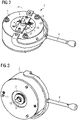
- Fig. 1a shows a service brake 1 that may be mounted atop a wind turbine yaw motor brake 20 via a brake housing 2.
- the wind turbine yaw motor brake 20 and a wind turbine yaw motor 21 are standard components of a wind turbine yaw drive and will not be discussed in detail herein.
- the wind turbine yaw drive houses a yaw motor shaft (not shown in fig. 1 ) which may be referred to as a shaft 22 to be braked (not shown in fig. 1 ).
- the wind turbine yaw motor brake 20 may become worn-out and it may be desirable to mount the service brake 1 atop the wind turbine yaw motor brake 20 in order to provide additional braking capacity to the wind turbine yaw drive.
- the service brake 1 comprises the brake housing 2 to which a lever 4 may be connected.
- the lever 4 may be used to activate or deactivate the service brake 1.
- Fig. 1a shows the lever 4 in "disengaged" position. This means that an internal brake disc 3 (not shown in fig. 1a ) is in a free-running state and the service brake 1 is deactivated.
- the brake housing 2 serves to house internal components of the service brake 1.
- the brake housing 2 may be cylindrical in shape and might match the wind turbine yaw motor brake 20 which might also be cylindrical with a diameter of the same size as the brake housing 2.
- Fig. 1b shows the service brake 1 in which the lever 4 is in "engaged" position. This means that the brake disc 3 (not shown in fig. 1b ) is not in a free-running state anymore i.e. the service brake 1 is activated.
- a service technician may insert a centerpiece 5 (not shown in fig. 1 ) which couples the shaft 22 to be braked and the service brake 1.
- the worn-out wind turbine yaw motor brake 20 is bypassed or its braking capacity supported with the service brake 1.
- the shaft 22 to be braked is braked by the service brake 1.
- the service technician puts the lever 4 in engaged position ( fig. 1b ).
- the service technician puts the lever 4 in disengaged position ( fig. 1a ) .
- lever 4 may also be performed by an electrically driven actuator acting upon the lever 4.
- Fig. 2 shows main components of the service brake 1.
- the service brake 1 comprises the brake housing 2 to which the lever 4 may be connected.
- the brake housing 2 may house the brake disc 3 (not shown in fig. 2 ).
- the brake housing 2 may be cylindrical in shape but other shapes of the brake housing 2 are possible.
- the brake housing 2 may be mountable vertically atop the wind turbine yaw motor brake 20 and may comprise a brake housing cavity 7 extending axially, in direction of a central axis (a), through the length of the brake housing 2.
- the brake housing 2 may be secured to the wind turbine yaw motor brake 20 with fastening means 6.
- the fastening means 6 are bolts.
- the removable centerpiece 5 that may be insertable within the brake housing cavity 7, along the central axis (a).
- the centerpiece 5 may be configured to engage with the brake disc 3 (shown in fig. 5 ) and with the shaft 22 to be braked and thereby to transfer braking torque from the brake disc 3 to the shaft 22 to be braked.
- Fig. 3 shows the service brake 1 from another view.
- the brake housing 2 may house the brake disc 3.
- the brake disc 3 is rotatable within the brake housing 2 about the central axis (a) in an airgap 12 between at least two friction plates 11 (see fig. 5 ).
- the centerpiece 5, as partially shown in fig. 3 is configured to engage with the brake disc 3 via a brake disc interface 9 (see fig. 4 ).
- the brake disc 3 may comprise a central opening 13 with a grooved surface 14 into which the brake disc interface 9 of the centerpiece 5 may be received.
- Bottom section of the centerpiece 5, as seen on fig. 3 may be a shaft interface 10, configured to engage with the shaft 22 to be braked.
- the shaft interface 10 of the centerpiece 5 may have a polygonal cross-sectional profile.
- the polygonal cross-sectional profile is a sextant profile as also shown in fig. 3 .
- the sextant profile of the shaft interface 10 may engage with a corresponding opening of the shaft 22 to be braked.
- Fig. 4 shows the removable centerpiece 5.
- Removable means that it can be manually - or via an actuating tool - inserted into the brake housing cavity 7 and/or manually removed from the brake housing cavity 7.
- the centerpiece 5 may comprise the already mentioned brake disc interface 9 which may be configured to engage with the brake disc 3 (not shown in fig. 4 ).
- the brake disc interface 9 is an externally grooved spline shaft 15 as shown in fig. 4 .
- the centerpiece 5 is insertable into the brake housing cavity 7.
- a first groove pattern of the spline shaft 15 may correspond to a second groove pattern of the surface 14 of the central opening 13.
- the externally grooved spline shaft 15 may engage with the central opening 13 of the brake disc 3. In this way direct coupling of the brake disc 3 and the centerpiece 5 is achieved.
- This interface defined by mating surfaces of the spline shaft 15 and the surface 14 of the second groove pattern allows the transmission of torque, like breaking torque.
- the centerpiece 5 may comprise the shaft interface 10, configured to engage with the shaft 22 to be braked (not shown in fig. 4 ).
- the shaft interface 10 has a polygonal cross-sectional profile.
- the polygonal profile is a sextant profile (shown in fig. 4 but which can better be seen in fig. 3 ).
- the centerpiece 5 may comprise a handle 8.
- the handle 8 may be used for manual insertion and/or removal of the centerpiece 5 into or from the brake housing cavity 7.
- the handle 8 may, in an embodiment, comprise a hole 16 for securing the centerpiece 5 on an external support member 17, for example via a pin 18 (see fig. 2 ).
- the external support member 17 may rest on top side of the brake housing 2.
- the top side of the brake housing 2 is the side facing away from the wind turbine yaw motor 21.
- the centerpiece 5 may be secured on the external support member 17 in a way that the handle 8 protrudes outwards of the brake housing cavity 7.
- Term outwards may be understood as, for example, along the central axis (a) in the direction facing away from the wind turbine yaw motor 21.
- the centerpiece 5 may be configured to engage with the brake disc 3 via the brake disc interface 9.
- the centerpiece 5 may also engage with the shaft 22 to be braked via the shaft interface 10. In this way direct coupling between the shaft 22 to be braked and the brake disc 3 may be achieved. If the service brake 1 is deactivated, any rotation of the shaft 22 to be braked is directly translated to the centerpiece 5 and in turn to the free-running brake disc 3. If the service brake 1 is activated, braking torque from the brake disc 3 is transferred to the shaft 22 to be braked.
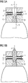
- Fig. 5a shows the service brake 1 mounted vertically atop the wind turbine yaw motor brake 20.
- the brake housing 2 comprises the brake housing cavity 7 which extends axially through the length of the brake housing 7 and in the direction - i.e. coaxially - of the central axis (a).
- the service brake 1 comprises the brake disc 3 within the brake housing 2.
- the brake disc 3 is rotatable about the central axis (a) in a surrounding airgap 12, between at least two friction plates 11.
- the friction plates 11 may be comprised in the brake housing 2.
- the brake disc 3 may be free-running if the service brake is deactivated.
- the shaft 22 to be braked as shown in fig. 5a , is decoupled from the brake disc 3 of the service brake 1 because the centerpiece 5 is not inserted in the brake housing cavity 7.
- This decoupling of the shaft 22 to be braked and the brake disc 3 is a safety feature of the service brake 1. This ensures that mounting of the activated service brake 1 on the yaw motor brake 20, even with the potentially spinning shaft 22 to be braked, does not result in propelling of the service brake 1.
- Fig. 5b shows the service brake 1 positioned vertically atop the wind turbine yaw motor brake 20 wherein the centerpiece 5 is inserted within the brake housing cavity 7, engaging both with the brake disc 3 and the shaft 22 to be braked.
- the centerpiece 5 may serve as a coupling means between the shaft 22 to be braked and the brake disc 3.
- any rotation of the shaft 22 to be braked translates directly to rotation of the brake disc 3, via the centerpiece 5.
- braking torque of the brake disc 3, via the centerpiece 5 is transferred to braking of the shaft 22 to be braked.
- Fig. 6 shows the service brake 1 with the centerpiece 5 inserted in the brake housing cavity 7, engaging both with the brake disc 3 and the shaft 22 to be braked. Furthermore, the lever 4 is shown to be in engaged position. This means that the service brake 1 is activated. The lever 4 may be brought to engaged position by the service technician in order to activate the service brake 1. By placing the lever 4 in engaged position as indicated in fig. 6 , at least a part of the airgap 12 is closed and the friction plates 11 are brought in frictional contact with the brake disc 3. The brake disc 3 may now transmit braking torque to the shaft 22 to be braked, via the centerpiece 5. The service brake 1 may in this way bypass the wind turbine yaw motor brake 20. Spring mechanism of the service brake 1 causing this frictional contact is not considered as part of the invention and is not discussed in detail. Several state-of-art braking mechanisms are known to person skilled-in-the-art.
- plurality of the wind turbine yaw motor brakes 20, comprised in a wind turbine yaw drive system may become worn-out. This situation may occur for example due to extreme wind load on the wind turbine. In such scenarios there may be a need to lock the complete wind turbine yaw drive system to enable safe repair of a wind turbine component.
- the wind turbine component may preferably be the worn-out wind turbine yaw motor brake 20 or other component inside the wind turbine.
- Method for locking the wind turbine yaw drive system which may comprise a plurality of wind turbine yaw motor brakes 20, may include a step of mounting a plurality of service brakes 1 atop the plurality of wind turbine yaw motor brakes 20.
- Each of the plurality of service brakes 1 may comprise already described components.
- the centerpieces 5 of each of the service brakes 1 may be inserted in the respective brake housing cavities 7. Afterwards, the service technician may bring the lever 4 of the service brake 1 of each of the plurality of service brakes 1 in engaged position.
- the wind turbine yaw drive system may, in this way, be safely locked.
- the number of the plurality of mounted service brakes 1 may correspond to the number of wind turbine yaw motor brakes 20 present in the wind turbine. This provides for a safe environment for service technicians performing inspection or service operations on the wind turbine component.
- the number of the plurality of mounted service brakes 1 may be less than the number of wind turbine yaw motor brakes 20 present in the wind turbine. This also may provide for a safe environment for service technicians to perform service operation on the wind turbine component.
- the wind turbine component may preferably be a further wind turbine yaw motor brake 20.
- the further wind turbine yaw motor brake may be free of the service brake 1, i.e. the service brake 1 may not be installed on the further wind turbine yaw motor brake 20.
- the wind turbine yaw drive system may comprise five to twenty, preferably eight to twelve, for example ten wind turbine yaw motor brakes 20 in total and all may become worn-out.
- the service technician may mount, in an exemplary system of ten wind turbine yaw motor brakes 20, nine service brakes 1 atop nine worn-out wind turbine yaw motor brakes 20 and leave preferably one yaw motor brake 20 without the service brake 1, i.e. the further wind turbine yaw motor brake 20. Then, the service technician may perform service operation on the further wind turbine yaw motor brake 20, onto which the service brake 1 is not mounted. In this way a sufficient braking capacity may be achieved which may safely hold the complete wind turbine yaw drive system braked while allowing for simultaneous service operation. In the mentioned example, it may also be possible to achieve similar results with mounting even fewer service brakes 1.
- X-1 number of service brakes 1 may be applied to enable servicing of the remaining wind turbine yaw motor brakes. More generally, X number of wind turbine yaw motor brakes are present in the wind turbine, X-N number of service brakes 1 may be applied to enable serving of the remaining number of N wind turbine yaw motor brakes.
- Performing service operation may comprise inspection, repair procedures or replacement of the wind turbine component with a replacement component.
Landscapes
- Engineering & Computer Science (AREA)
- Life Sciences & Earth Sciences (AREA)
- Sustainable Development (AREA)
- Sustainable Energy (AREA)
- Chemical & Material Sciences (AREA)
- Combustion & Propulsion (AREA)
- Mechanical Engineering (AREA)
- General Engineering & Computer Science (AREA)
- Braking Arrangements (AREA)
- Wind Motors (AREA)
Priority Applications (9)
| Application Number | Priority Date | Filing Date | Title |
|---|---|---|---|
| EP21187330.2A EP4123166A1 (de) | 2021-07-23 | 2021-07-23 | Instandhaltungsbremse für eine windkraftanlagen-nachführmotor-bremse |
| BR112023026800A BR112023026800A2 (pt) | 2021-07-23 | 2022-07-07 | Freio de serviço para um motor de guinada de turbina eólica |
| US18/579,880 US12497946B2 (en) | 2021-07-23 | 2022-07-07 | Service brake for a wind turbine yaw motor |
| EP22738688.5A EP4330541B1 (de) | 2021-07-23 | 2022-07-07 | Instandhaltungsbremse für eine windkraftanlagen-nachführmotor-bremse |
| AU2022313426A AU2022313426B2 (en) | 2021-07-23 | 2022-07-07 | Service brake for a wind turbine yaw motor |
| KR1020247002277A KR20240023163A (ko) | 2021-07-23 | 2022-07-07 | 풍력 터빈 요 모터용 서비스 브레이크 |
| CN202280051383.8A CN117730201A (zh) | 2021-07-23 | 2022-07-07 | 用于风力涡轮机偏航马达的维修制动器 |
| PL22738688.5T PL4330541T3 (pl) | 2021-07-23 | 2022-07-07 | Hamulec serwisowy dla silnika odchylania turbiny wiatrowej |
| PCT/EP2022/068828 WO2023001564A1 (en) | 2021-07-23 | 2022-07-07 | Service brake for a wind turbine yaw motor |
Applications Claiming Priority (1)
| Application Number | Priority Date | Filing Date | Title |
|---|---|---|---|
| EP21187330.2A EP4123166A1 (de) | 2021-07-23 | 2021-07-23 | Instandhaltungsbremse für eine windkraftanlagen-nachführmotor-bremse |
Publications (1)
| Publication Number | Publication Date |
|---|---|
| EP4123166A1 true EP4123166A1 (de) | 2023-01-25 |
Family
ID=77042779
Family Applications (2)
| Application Number | Title | Priority Date | Filing Date |
|---|---|---|---|
| EP21187330.2A Withdrawn EP4123166A1 (de) | 2021-07-23 | 2021-07-23 | Instandhaltungsbremse für eine windkraftanlagen-nachführmotor-bremse |
| EP22738688.5A Active EP4330541B1 (de) | 2021-07-23 | 2022-07-07 | Instandhaltungsbremse für eine windkraftanlagen-nachführmotor-bremse |
Family Applications After (1)
| Application Number | Title | Priority Date | Filing Date |
|---|---|---|---|
| EP22738688.5A Active EP4330541B1 (de) | 2021-07-23 | 2022-07-07 | Instandhaltungsbremse für eine windkraftanlagen-nachführmotor-bremse |
Country Status (8)
| Country | Link |
|---|---|
| US (1) | US12497946B2 (de) |
| EP (2) | EP4123166A1 (de) |
| KR (1) | KR20240023163A (de) |
| CN (1) | CN117730201A (de) |
| AU (1) | AU2022313426B2 (de) |
| BR (1) | BR112023026800A2 (de) |
| PL (1) | PL4330541T3 (de) |
| WO (1) | WO2023001564A1 (de) |
Citations (4)
| Publication number | Priority date | Publication date | Assignee | Title |
|---|---|---|---|---|
| CN103785989B (zh) * | 2014-01-23 | 2016-05-18 | 广东明阳风电产业集团有限公司 | 一种风力发电机组的偏航制动盘高空修复方法 |
| EP3139058A1 (de) * | 2015-09-04 | 2017-03-08 | S.B. Patent Holding ApS | Wartungssystem und verfahren zur wartung einer bremsvorrichtung eines bremssystems mit einer horizontal angeordneten bremsscheibe |
| CN209380646U (zh) * | 2018-12-21 | 2019-09-13 | 大唐(赤峰)新能源有限公司 | 一种风力发电机组偏航制动器更换工具 |
| EP3412907B1 (de) * | 2017-06-07 | 2021-01-20 | S.B. Patent Holding ApS | Mehrflächiges azimuth-bremssystem für eine windturbine |
Family Cites Families (20)
| Publication number | Priority date | Publication date | Assignee | Title |
|---|---|---|---|---|
| US2153523A (en) * | 1937-03-25 | 1939-04-04 | W N Price | Wind operated electric generator |
| US2214807A (en) * | 1940-05-01 | 1940-09-17 | Shepard Niles Crane & Hoist Co | Motor control and brake mechanism |
| US3633714A (en) * | 1969-08-01 | 1972-01-11 | Hermann Klaue | Full disc brake with rotating brake discs |
| US20100038192A1 (en) * | 2008-08-15 | 2010-02-18 | Culbertson Michael O | Floating yaw brake for wind turbine |
| EP2354539B1 (de) * | 2010-01-14 | 2012-05-23 | Nordex Energy GmbH | Windenergieanlage mit einem Azimutsystem sowie Verfahren zur Azimutverstellung einer Windenergieanlage |
| WO2013040606A1 (en) * | 2011-09-18 | 2013-03-21 | Withers Graham R | Externally vented aluminum disc brake rotor |
| US20130088009A1 (en) * | 2011-10-11 | 2013-04-11 | Clipper Windpower, Llc | Method to Prevent Over Torque of Yaw Drive Components in a Wind Turbine |
| TW201418595A (zh) * | 2012-11-14 | 2014-05-16 | Sirius Disc Brake Technology Ltd | 機械式碟煞機構 |
| KR101571445B1 (ko) * | 2014-06-26 | 2015-11-24 | 삼성중공업 주식회사 | 풍력발전용 요 브레이크 시스템 |
| KR101576751B1 (ko) * | 2014-11-04 | 2015-12-10 | 두산중공업 주식회사 | 풍력 발전기의 요 브레이크 유닛 및 이를 이용한 제어방법 |
| KR20170000750U (ko) * | 2015-08-19 | 2017-03-02 | 대우조선해양 주식회사 | 풍력발전기의 요 브레이크 디스크 클리너 |
| CN106545600B (zh) * | 2016-12-08 | 2019-03-15 | 北京金风科创风电设备有限公司 | 风力发电机组及其偏航制动装置、制动系统和制动方法 |
| US20180320661A1 (en) * | 2017-05-03 | 2018-11-08 | General Electric Company | Compact Multi-Disk Rotor Brake System for a Wind Turbine |
| CN208252641U (zh) * | 2018-06-05 | 2018-12-18 | 孙正彦 | 偏航干式制动器 |
| CN108825433B (zh) * | 2018-06-29 | 2020-05-26 | 乌鲁木齐金风天翼风电有限公司 | 用于风力发电机组的偏航制动装置及风力发电机组 |
| EP3670901B1 (de) * | 2018-12-18 | 2023-01-25 | Nordex Energy Spain, S.A.U. | Verfahren zum versetzen des gierlagers einer windkraftanlage |
| CN209163997U (zh) * | 2018-12-21 | 2019-07-26 | 新疆金风科技股份有限公司 | 风力发电机组及其偏航控制系统 |
| CN110425093A (zh) * | 2019-08-29 | 2019-11-08 | 南京高速齿轮制造有限公司 | 一种风力发电机组盘车装置 |
| DE102019126348B4 (de) * | 2019-09-30 | 2023-06-15 | Schunk Carbon Technology Gmbh | Azimutbremseinrichtung |
| JP7508222B2 (ja) * | 2019-12-25 | 2024-07-01 | ナブテスコ株式会社 | 風力発電装置、制御方法、およびプログラム |
-
2021
- 2021-07-23 EP EP21187330.2A patent/EP4123166A1/de not_active Withdrawn
-
2022
- 2022-07-07 KR KR1020247002277A patent/KR20240023163A/ko active Pending
- 2022-07-07 CN CN202280051383.8A patent/CN117730201A/zh active Pending
- 2022-07-07 PL PL22738688.5T patent/PL4330541T3/pl unknown
- 2022-07-07 EP EP22738688.5A patent/EP4330541B1/de active Active
- 2022-07-07 WO PCT/EP2022/068828 patent/WO2023001564A1/en not_active Ceased
- 2022-07-07 BR BR112023026800A patent/BR112023026800A2/pt unknown
- 2022-07-07 AU AU2022313426A patent/AU2022313426B2/en active Active
- 2022-07-07 US US18/579,880 patent/US12497946B2/en active Active
Patent Citations (4)
| Publication number | Priority date | Publication date | Assignee | Title |
|---|---|---|---|---|
| CN103785989B (zh) * | 2014-01-23 | 2016-05-18 | 广东明阳风电产业集团有限公司 | 一种风力发电机组的偏航制动盘高空修复方法 |
| EP3139058A1 (de) * | 2015-09-04 | 2017-03-08 | S.B. Patent Holding ApS | Wartungssystem und verfahren zur wartung einer bremsvorrichtung eines bremssystems mit einer horizontal angeordneten bremsscheibe |
| EP3412907B1 (de) * | 2017-06-07 | 2021-01-20 | S.B. Patent Holding ApS | Mehrflächiges azimuth-bremssystem für eine windturbine |
| CN209380646U (zh) * | 2018-12-21 | 2019-09-13 | 大唐(赤峰)新能源有限公司 | 一种风力发电机组偏航制动器更换工具 |
Also Published As
| Publication number | Publication date |
|---|---|
| KR20240023163A (ko) | 2024-02-20 |
| BR112023026800A2 (pt) | 2024-03-12 |
| CN117730201A (zh) | 2024-03-19 |
| WO2023001564A1 (en) | 2023-01-26 |
| EP4330541B1 (de) | 2025-01-29 |
| AU2022313426B2 (en) | 2025-07-10 |
| EP4330541A1 (de) | 2024-03-06 |
| US12497946B2 (en) | 2025-12-16 |
| US20240337246A1 (en) | 2024-10-10 |
| PL4330541T3 (pl) | 2025-04-07 |
| AU2022313426A1 (en) | 2024-01-04 |
| EP4330541C0 (de) | 2025-01-29 |
Similar Documents
| Publication | Publication Date | Title |
|---|---|---|
| EP2406490B1 (de) | Rotorverriegelung für eine windturbine | |
| US11280320B2 (en) | Yaw system for a wind turbine | |
| EP2630367B1 (de) | Windturbinenleistungsübertragungssystem und verfahren zur installation einer windenergieanlage damit | |
| CN102536635B (zh) | 用于将转子叶片安装在风力涡轮机上的方法和设备 | |
| EP1772624B1 (de) | Elektrischer Generator einer Direktantrieb-Windenergieanlage mit austauschbarer Lagervorrichtung | |
| EP2005558B1 (de) | Elektrischer generator für wind- und wasserturbinen | |
| EP2381560A1 (de) | Windkraftturbine mit Generator und mit derartigem Generator ausgestattete Windkraftturbine | |
| US8313297B2 (en) | Rotor shaft for a wind energy plant and wind energy plant | |
| EP2987999B1 (de) | Vorrichtung und Verfahren zum Drehen eines Windturbinenrotors | |
| EP3722601B1 (de) | Windturbine | |
| EP4330541B1 (de) | Instandhaltungsbremse für eine windkraftanlagen-nachführmotor-bremse | |
| CA2562596A1 (en) | Device for driving a first part of a wind energy turbine with respect to a second part of the wind energy turbine | |
| EP4102065B1 (de) | Nabe-welle-bolzenverbindung einer windturbine | |
| EP3719310A1 (de) | Rotordrehvorrichtung für eine windturbine | |
| CN104105873B (zh) | 用于固定风能发电站的转子叶片的组件 | |
| EP2607684A1 (de) | Mittel zum Drehen des Rotors einer Windturbine und Verfahren zum Drehen des Rotors | |
| CN121693624A (zh) | 操作设备 | |
| CN121273849A (zh) | 一种液压驱动机构及风力发电设备机舱转向驱动装置 |
Legal Events
| Date | Code | Title | Description |
|---|---|---|---|
| PUAI | Public reference made under article 153(3) epc to a published international application that has entered the european phase |
Free format text: ORIGINAL CODE: 0009012 |
|
| STAA | Information on the status of an ep patent application or granted ep patent |
Free format text: STATUS: THE APPLICATION HAS BEEN PUBLISHED |
|
| AK | Designated contracting states |
Kind code of ref document: A1 Designated state(s): AL AT BE BG CH CY CZ DE DK EE ES FI FR GB GR HR HU IE IS IT LI LT LU LV MC MK MT NL NO PL PT RO RS SE SI SK SM TR |
|
| STAA | Information on the status of an ep patent application or granted ep patent |
Free format text: STATUS: THE APPLICATION IS DEEMED TO BE WITHDRAWN |
|
| 18D | Application deemed to be withdrawn |
Effective date: 20230726 |