EP4123190B1 - Mechanisches untersetzungsgetriebe für gasturbomaschinen mit längsachse - Google Patents
Mechanisches untersetzungsgetriebe für gasturbomaschinen mit längsachse Download PDFInfo
- Publication number
- EP4123190B1 EP4123190B1 EP22186556.1A EP22186556A EP4123190B1 EP 4123190 B1 EP4123190 B1 EP 4123190B1 EP 22186556 A EP22186556 A EP 22186556A EP 4123190 B1 EP4123190 B1 EP 4123190B1
- Authority
- EP
- European Patent Office
- Prior art keywords
- annular
- annular part
- pivot
- annular groove
- oil
- Prior art date
- Legal status (The legal status is an assumption and is not a legal conclusion. Google has not performed a legal analysis and makes no representation as to the accuracy of the status listed.)
- Active
Links
Images




Classifications
-
- F—MECHANICAL ENGINEERING; LIGHTING; HEATING; WEAPONS; BLASTING
- F16—ENGINEERING ELEMENTS AND UNITS; GENERAL MEASURES FOR PRODUCING AND MAINTAINING EFFECTIVE FUNCTIONING OF MACHINES OR INSTALLATIONS; THERMAL INSULATION IN GENERAL
- F16H—GEARING
- F16H57/00—General details of gearing
- F16H57/04—Features relating to lubrication or cooling or heating
- F16H57/048—Type of gearings to be lubricated, cooled or heated
- F16H57/0482—Gearings with gears having orbital motion
-
- F—MECHANICAL ENGINEERING; LIGHTING; HEATING; WEAPONS; BLASTING
- F16—ENGINEERING ELEMENTS AND UNITS; GENERAL MEASURES FOR PRODUCING AND MAINTAINING EFFECTIVE FUNCTIONING OF MACHINES OR INSTALLATIONS; THERMAL INSULATION IN GENERAL
- F16C—SHAFTS; FLEXIBLE SHAFTS; ELEMENTS OR CRANKSHAFT MECHANISMS; ROTARY BODIES OTHER THAN GEARING ELEMENTS; BEARINGS
- F16C11/00—Pivots; Pivotal connections
- F16C11/02—Trunnions; Crank-pins
-
- F—MECHANICAL ENGINEERING; LIGHTING; HEATING; WEAPONS; BLASTING
- F16—ENGINEERING ELEMENTS AND UNITS; GENERAL MEASURES FOR PRODUCING AND MAINTAINING EFFECTIVE FUNCTIONING OF MACHINES OR INSTALLATIONS; THERMAL INSULATION IN GENERAL
- F16C—SHAFTS; FLEXIBLE SHAFTS; ELEMENTS OR CRANKSHAFT MECHANISMS; ROTARY BODIES OTHER THAN GEARING ELEMENTS; BEARINGS
- F16C17/00—Sliding-contact bearings for exclusively rotary movement
- F16C17/02—Sliding-contact bearings for exclusively rotary movement for radial load only
-
- F—MECHANICAL ENGINEERING; LIGHTING; HEATING; WEAPONS; BLASTING
- F16—ENGINEERING ELEMENTS AND UNITS; GENERAL MEASURES FOR PRODUCING AND MAINTAINING EFFECTIVE FUNCTIONING OF MACHINES OR INSTALLATIONS; THERMAL INSULATION IN GENERAL
- F16C—SHAFTS; FLEXIBLE SHAFTS; ELEMENTS OR CRANKSHAFT MECHANISMS; ROTARY BODIES OTHER THAN GEARING ELEMENTS; BEARINGS
- F16C17/00—Sliding-contact bearings for exclusively rotary movement
- F16C17/02—Sliding-contact bearings for exclusively rotary movement for radial load only
- F16C17/022—Sliding-contact bearings for exclusively rotary movement for radial load only with a pair of essentially semicircular bearing sleeves
-
- F—MECHANICAL ENGINEERING; LIGHTING; HEATING; WEAPONS; BLASTING
- F16—ENGINEERING ELEMENTS AND UNITS; GENERAL MEASURES FOR PRODUCING AND MAINTAINING EFFECTIVE FUNCTIONING OF MACHINES OR INSTALLATIONS; THERMAL INSULATION IN GENERAL
- F16C—SHAFTS; FLEXIBLE SHAFTS; ELEMENTS OR CRANKSHAFT MECHANISMS; ROTARY BODIES OTHER THAN GEARING ELEMENTS; BEARINGS
- F16C17/00—Sliding-contact bearings for exclusively rotary movement
- F16C17/02—Sliding-contact bearings for exclusively rotary movement for radial load only
- F16C17/024—Sliding-contact bearings for exclusively rotary movement for radial load only with flexible leaves to create hydrodynamic wedge, e.g. radial foil bearings
-
- F—MECHANICAL ENGINEERING; LIGHTING; HEATING; WEAPONS; BLASTING
- F16—ENGINEERING ELEMENTS AND UNITS; GENERAL MEASURES FOR PRODUCING AND MAINTAINING EFFECTIVE FUNCTIONING OF MACHINES OR INSTALLATIONS; THERMAL INSULATION IN GENERAL
- F16C—SHAFTS; FLEXIBLE SHAFTS; ELEMENTS OR CRANKSHAFT MECHANISMS; ROTARY BODIES OTHER THAN GEARING ELEMENTS; BEARINGS
- F16C17/00—Sliding-contact bearings for exclusively rotary movement
- F16C17/02—Sliding-contact bearings for exclusively rotary movement for radial load only
- F16C17/026—Sliding-contact bearings for exclusively rotary movement for radial load only with helical grooves in the bearing surface to generate hydrodynamic pressure, e.g. herringbone grooves
-
- F—MECHANICAL ENGINEERING; LIGHTING; HEATING; WEAPONS; BLASTING
- F16—ENGINEERING ELEMENTS AND UNITS; GENERAL MEASURES FOR PRODUCING AND MAINTAINING EFFECTIVE FUNCTIONING OF MACHINES OR INSTALLATIONS; THERMAL INSULATION IN GENERAL
- F16C—SHAFTS; FLEXIBLE SHAFTS; ELEMENTS OR CRANKSHAFT MECHANISMS; ROTARY BODIES OTHER THAN GEARING ELEMENTS; BEARINGS
- F16C17/00—Sliding-contact bearings for exclusively rotary movement
- F16C17/02—Sliding-contact bearings for exclusively rotary movement for radial load only
- F16C17/028—Sliding-contact bearings for exclusively rotary movement for radial load only with fixed wedges to generate hydrodynamic pressure, e.g. multi-lobe bearings
-
- F—MECHANICAL ENGINEERING; LIGHTING; HEATING; WEAPONS; BLASTING
- F16—ENGINEERING ELEMENTS AND UNITS; GENERAL MEASURES FOR PRODUCING AND MAINTAINING EFFECTIVE FUNCTIONING OF MACHINES OR INSTALLATIONS; THERMAL INSULATION IN GENERAL
- F16C—SHAFTS; FLEXIBLE SHAFTS; ELEMENTS OR CRANKSHAFT MECHANISMS; ROTARY BODIES OTHER THAN GEARING ELEMENTS; BEARINGS
- F16C17/00—Sliding-contact bearings for exclusively rotary movement
- F16C17/12—Sliding-contact bearings for exclusively rotary movement characterised by features not related to the direction of the load
- F16C17/24—Sliding-contact bearings for exclusively rotary movement characterised by features not related to the direction of the load with devices affected by abnormal or undesired positions, e.g. for preventing overheating, for safety
- F16C17/243—Sliding-contact bearings for exclusively rotary movement characterised by features not related to the direction of the load with devices affected by abnormal or undesired positions, e.g. for preventing overheating, for safety related to temperature and heat, e.g. for preventing overheating
-
- F—MECHANICAL ENGINEERING; LIGHTING; HEATING; WEAPONS; BLASTING
- F16—ENGINEERING ELEMENTS AND UNITS; GENERAL MEASURES FOR PRODUCING AND MAINTAINING EFFECTIVE FUNCTIONING OF MACHINES OR INSTALLATIONS; THERMAL INSULATION IN GENERAL
- F16C—SHAFTS; FLEXIBLE SHAFTS; ELEMENTS OR CRANKSHAFT MECHANISMS; ROTARY BODIES OTHER THAN GEARING ELEMENTS; BEARINGS
- F16C19/00—Bearings with rolling contact, for exclusively rotary movement
- F16C19/02—Bearings with rolling contact, for exclusively rotary movement with bearing balls essentially of the same size in one or more circular rows
- F16C19/04—Bearings with rolling contact, for exclusively rotary movement with bearing balls essentially of the same size in one or more circular rows for radial load mainly
-
- F—MECHANICAL ENGINEERING; LIGHTING; HEATING; WEAPONS; BLASTING
- F16—ENGINEERING ELEMENTS AND UNITS; GENERAL MEASURES FOR PRODUCING AND MAINTAINING EFFECTIVE FUNCTIONING OF MACHINES OR INSTALLATIONS; THERMAL INSULATION IN GENERAL
- F16C—SHAFTS; FLEXIBLE SHAFTS; ELEMENTS OR CRANKSHAFT MECHANISMS; ROTARY BODIES OTHER THAN GEARING ELEMENTS; BEARINGS
- F16C19/00—Bearings with rolling contact, for exclusively rotary movement
- F16C19/22—Bearings with rolling contact, for exclusively rotary movement with bearing rollers essentially of the same size in one or more circular rows, e.g. needle bearings
- F16C19/24—Bearings with rolling contact, for exclusively rotary movement with bearing rollers essentially of the same size in one or more circular rows, e.g. needle bearings for radial load mainly
-
- F—MECHANICAL ENGINEERING; LIGHTING; HEATING; WEAPONS; BLASTING
- F16—ENGINEERING ELEMENTS AND UNITS; GENERAL MEASURES FOR PRODUCING AND MAINTAINING EFFECTIVE FUNCTIONING OF MACHINES OR INSTALLATIONS; THERMAL INSULATION IN GENERAL
- F16C—SHAFTS; FLEXIBLE SHAFTS; ELEMENTS OR CRANKSHAFT MECHANISMS; ROTARY BODIES OTHER THAN GEARING ELEMENTS; BEARINGS
- F16C19/00—Bearings with rolling contact, for exclusively rotary movement
- F16C19/22—Bearings with rolling contact, for exclusively rotary movement with bearing rollers essentially of the same size in one or more circular rows, e.g. needle bearings
- F16C19/44—Needle bearings
-
- F—MECHANICAL ENGINEERING; LIGHTING; HEATING; WEAPONS; BLASTING
- F16—ENGINEERING ELEMENTS AND UNITS; GENERAL MEASURES FOR PRODUCING AND MAINTAINING EFFECTIVE FUNCTIONING OF MACHINES OR INSTALLATIONS; THERMAL INSULATION IN GENERAL
- F16C—SHAFTS; FLEXIBLE SHAFTS; ELEMENTS OR CRANKSHAFT MECHANISMS; ROTARY BODIES OTHER THAN GEARING ELEMENTS; BEARINGS
- F16C19/00—Bearings with rolling contact, for exclusively rotary movement
- F16C19/52—Bearings with rolling contact, for exclusively rotary movement with devices affected by abnormal or undesired conditions
- F16C19/525—Bearings with rolling contact, for exclusively rotary movement with devices affected by abnormal or undesired conditions related to temperature and heat, e.g. insulation
-
- F—MECHANICAL ENGINEERING; LIGHTING; HEATING; WEAPONS; BLASTING
- F16—ENGINEERING ELEMENTS AND UNITS; GENERAL MEASURES FOR PRODUCING AND MAINTAINING EFFECTIVE FUNCTIONING OF MACHINES OR INSTALLATIONS; THERMAL INSULATION IN GENERAL
- F16C—SHAFTS; FLEXIBLE SHAFTS; ELEMENTS OR CRANKSHAFT MECHANISMS; ROTARY BODIES OTHER THAN GEARING ELEMENTS; BEARINGS
- F16C33/00—Parts of bearings; Special methods for making bearings or parts thereof
- F16C33/02—Parts of sliding-contact bearings
- F16C33/04—Brasses; Bushes; Linings
- F16C33/06—Sliding surface mainly made of metal
- F16C33/10—Construction relative to lubrication
- F16C33/1025—Construction relative to lubrication with liquid, e.g. oil, as lubricant
- F16C33/1045—Details of supply of the liquid to the bearing
- F16C33/105—Conditioning, e.g. metering, cooling, filtering
-
- F—MECHANICAL ENGINEERING; LIGHTING; HEATING; WEAPONS; BLASTING
- F16—ENGINEERING ELEMENTS AND UNITS; GENERAL MEASURES FOR PRODUCING AND MAINTAINING EFFECTIVE FUNCTIONING OF MACHINES OR INSTALLATIONS; THERMAL INSULATION IN GENERAL
- F16C—SHAFTS; FLEXIBLE SHAFTS; ELEMENTS OR CRANKSHAFT MECHANISMS; ROTARY BODIES OTHER THAN GEARING ELEMENTS; BEARINGS
- F16C33/00—Parts of bearings; Special methods for making bearings or parts thereof
- F16C33/02—Parts of sliding-contact bearings
- F16C33/04—Brasses; Bushes; Linings
- F16C33/06—Sliding surface mainly made of metal
- F16C33/10—Construction relative to lubrication
- F16C33/1025—Construction relative to lubrication with liquid, e.g. oil, as lubricant
- F16C33/1045—Details of supply of the liquid to the bearing
- F16C33/1055—Details of supply of the liquid to the bearing from radial inside, e.g. via a passage through the shaft and/or inner sleeve
-
- F—MECHANICAL ENGINEERING; LIGHTING; HEATING; WEAPONS; BLASTING
- F16—ENGINEERING ELEMENTS AND UNITS; GENERAL MEASURES FOR PRODUCING AND MAINTAINING EFFECTIVE FUNCTIONING OF MACHINES OR INSTALLATIONS; THERMAL INSULATION IN GENERAL
- F16C—SHAFTS; FLEXIBLE SHAFTS; ELEMENTS OR CRANKSHAFT MECHANISMS; ROTARY BODIES OTHER THAN GEARING ELEMENTS; BEARINGS
- F16C37/00—Cooling of bearings
- F16C37/002—Cooling of bearings of fluid bearings
-
- F—MECHANICAL ENGINEERING; LIGHTING; HEATING; WEAPONS; BLASTING
- F16—ENGINEERING ELEMENTS AND UNITS; GENERAL MEASURES FOR PRODUCING AND MAINTAINING EFFECTIVE FUNCTIONING OF MACHINES OR INSTALLATIONS; THERMAL INSULATION IN GENERAL
- F16C—SHAFTS; FLEXIBLE SHAFTS; ELEMENTS OR CRANKSHAFT MECHANISMS; ROTARY BODIES OTHER THAN GEARING ELEMENTS; BEARINGS
- F16C37/00—Cooling of bearings
- F16C37/007—Cooling of bearings of rolling bearings
-
- F—MECHANICAL ENGINEERING; LIGHTING; HEATING; WEAPONS; BLASTING
- F16—ENGINEERING ELEMENTS AND UNITS; GENERAL MEASURES FOR PRODUCING AND MAINTAINING EFFECTIVE FUNCTIONING OF MACHINES OR INSTALLATIONS; THERMAL INSULATION IN GENERAL
- F16H—GEARING
- F16H1/00—Toothed gearings for conveying rotary motion
- F16H1/28—Toothed gearings for conveying rotary motion with gears having orbital motion
-
- F—MECHANICAL ENGINEERING; LIGHTING; HEATING; WEAPONS; BLASTING
- F16—ENGINEERING ELEMENTS AND UNITS; GENERAL MEASURES FOR PRODUCING AND MAINTAINING EFFECTIVE FUNCTIONING OF MACHINES OR INSTALLATIONS; THERMAL INSULATION IN GENERAL
- F16H—GEARING
- F16H57/00—General details of gearing
- F16H57/04—Features relating to lubrication or cooling or heating
- F16H57/042—Guidance of lubricant
- F16H57/0427—Guidance of lubricant on rotary parts, e.g. using baffles for collecting lubricant by centrifugal force
-
- F—MECHANICAL ENGINEERING; LIGHTING; HEATING; WEAPONS; BLASTING
- F16—ENGINEERING ELEMENTS AND UNITS; GENERAL MEASURES FOR PRODUCING AND MAINTAINING EFFECTIVE FUNCTIONING OF MACHINES OR INSTALLATIONS; THERMAL INSULATION IN GENERAL
- F16H—GEARING
- F16H57/00—General details of gearing
- F16H57/04—Features relating to lubrication or cooling or heating
- F16H57/042—Guidance of lubricant
- F16H57/043—Guidance of lubricant within rotary parts, e.g. axial channels or radial openings in shafts
-
- F—MECHANICAL ENGINEERING; LIGHTING; HEATING; WEAPONS; BLASTING
- F05—INDEXING SCHEMES RELATING TO ENGINES OR PUMPS IN VARIOUS SUBCLASSES OF CLASSES F01-F04
- F05D—INDEXING SCHEME FOR ASPECTS RELATING TO NON-POSITIVE-DISPLACEMENT MACHINES OR ENGINES, GAS-TURBINES OR JET-PROPULSION PLANTS
- F05D2260/00—Function
- F05D2260/40—Transmission of power
- F05D2260/403—Transmission of power through the shape of the drive components
- F05D2260/4031—Transmission of power through the shape of the drive components as in toothed gearing
- F05D2260/40311—Transmission of power through the shape of the drive components as in toothed gearing of the epicyclical, planetary or differential type
-
- F—MECHANICAL ENGINEERING; LIGHTING; HEATING; WEAPONS; BLASTING
- F16—ENGINEERING ELEMENTS AND UNITS; GENERAL MEASURES FOR PRODUCING AND MAINTAINING EFFECTIVE FUNCTIONING OF MACHINES OR INSTALLATIONS; THERMAL INSULATION IN GENERAL
- F16C—SHAFTS; FLEXIBLE SHAFTS; ELEMENTS OR CRANKSHAFT MECHANISMS; ROTARY BODIES OTHER THAN GEARING ELEMENTS; BEARINGS
- F16C2360/00—Engines or pumps
- F16C2360/23—Gas turbine engines
-
- F—MECHANICAL ENGINEERING; LIGHTING; HEATING; WEAPONS; BLASTING
- F16—ENGINEERING ELEMENTS AND UNITS; GENERAL MEASURES FOR PRODUCING AND MAINTAINING EFFECTIVE FUNCTIONING OF MACHINES OR INSTALLATIONS; THERMAL INSULATION IN GENERAL
- F16C—SHAFTS; FLEXIBLE SHAFTS; ELEMENTS OR CRANKSHAFT MECHANISMS; ROTARY BODIES OTHER THAN GEARING ELEMENTS; BEARINGS
- F16C2361/00—Apparatus or articles in engineering in general
- F16C2361/61—Toothed gear systems, e.g. support of pinion shafts
-
- Y—GENERAL TAGGING OF NEW TECHNOLOGICAL DEVELOPMENTS; GENERAL TAGGING OF CROSS-SECTIONAL TECHNOLOGIES SPANNING OVER SEVERAL SECTIONS OF THE IPC; TECHNICAL SUBJECTS COVERED BY FORMER USPC CROSS-REFERENCE ART COLLECTIONS [XRACs] AND DIGESTS
- Y02—TECHNOLOGIES OR APPLICATIONS FOR MITIGATION OR ADAPTATION AGAINST CLIMATE CHANGE
- Y02T—CLIMATE CHANGE MITIGATION TECHNOLOGIES RELATED TO TRANSPORTATION
- Y02T50/00—Aeronautics or air transport
- Y02T50/60—Efficient propulsion technologies, e.g. for aircraft
Definitions
- the present invention relates to a pivot for a bearing and more particularly to a pivot intended to be integrated into a reducer of a turbomachine such as a turbojet or a turboprop.
- the role of a mechanical reducer is to modify the speed and torque ratio between the input shaft and the output shaft of a mechanism.
- New generations of dual-flow turbomachines particularly those with a high bypass ratio, include a mechanical reducer to drive the shaft of a fan.
- the reducer is intended to transform the so-called fast rotation speed of the shaft of a power turbine into a slower rotation speed for the shaft driving the fan.
- Such a reducer comprises a central pinion, called a sun gear, a crown gear and pinions called satellites, which are meshed between the sun gear and the crown gear.
- the satellites are held by a frame called a planet carrier.
- the sun gear, the crown gear and the planet carrier are planet gears because their axes of revolution coincide with the longitudinal axis X of the turbomachine.
- the satellites each have a different axis of revolution Y, they are equally distributed on a circle around the axis of the planet gears. These Y axes are parallel to the longitudinal axis X.
- Gearboxes can include one or more meshing stages. This meshing is ensured in different ways such as by contact, by friction or by magnetic fields. There are several types of contact meshing such as with straight or herringbone teeth.
- Each satellite carried by the satellite carrier is mounted to rotate freely on a pivot.
- the use of a pivot forming a plain bearing with a satellite pinion reduces the size and weight and offers a virtually infinite service life, provided that they are constantly supplied with lubricating and cooling oil.
- a pivot can be used with a rolling bearing of which an internal ring would be carried by the pivot, the external ring then being integral in rotation with a satellite.
- a mechanical reducer for a gas turbomachine with a longitudinal axis comprising a crown and satellites engaged with a sun gear and with the crown and each mounted free to rotate about their axis on a planet carrier, the satellites being configured to each rotate about their axis by means of a pivot for a bearing, the pivot comprising a first annular part comprising an axial lubrication passage and a second annular part mounted around the first annular part, the first annular part delimiting with the second annular part a lubrication circuit of which at least one oil inlet opens inside the first annular part in the axial passage and at least one oil outlet opens radially outside the second annular part.
- the pivot is made in two separate parts and an oil circuit is made in the pivot so as to cool the pivot.
- an oil circuit is made in the pivot so as to cool the pivot.
- the first annular part comprises an annular wall in which are formed a plurality of annular grooves around which the second annular part is mounted in a sealed manner.
- the annular grooves are open radially outwards and the radially external outlets of the annular grooves are closed by the second annular part.
- the lubricating oil circuit comprises a plurality of annular grooves formed in an annular wall, the second annular part being mounted around the annular grooves and sealingly mounted around them.
- the first annular part and the second annular part can be made by casting or by additive manufacturing.
- the assembly makes it possible to simplify the design of the first annular part and the second annular part.
- the annular grooves may be in fluid communication with each other.
- the oil inlet of the lubricating oil circuit opens into an annular groove positioned longitudinally at half the length of the pivot.
- the pivot may comprise 2k+1 annular grooves, k being a positive integer, preferably greater than or equal to 3. In a particular embodiment, the number of annular grooves may be equal to 5.
- the annular grooves communicate fluidically by means of openings, such as slots, formed in annular partitions separating the annular grooves. Orifices may be formed in the annular partitions.
- Each groove comprises a radial wall joining two consecutive partitions so as to prevent the circulation of oil over 360°, each radial wall circumferentially separating a first circumferential end of the annular groove and a second circumferential end of the annular groove, each annular groove including an oil inlet at its first circumferential end and an oil outlet at its second circumferential end.
- the oil thus circulates circumferentially from the first circumferential end of an annular groove to the second circumferential end of said annular groove so as to allow oil circulation over substantially 360° and thus cool the pivot annularly as best as possible.
- the two annular grooves of longitudinal ends can each comprise an oil outlet connected to a channel, a downstream end of which opens radially outside the second annular part.
- the invention also relates to a gas turbomachine for an aircraft comprising such a mechanical reducer whose sun gear surrounds and is integral in rotation with a shaft of the compressor of the turbomachine.
- the turbomachine can also be such that the crown is integral with a static annular casing or shell of the low pressure compressor.
- the pivot according to this document can be used in a hydrodynamic plain bearing or in a rolling bearing, for example ball or roller bearing.
- turbomachine 1 which comprises, in a conventional manner, a fan S, a low-pressure compressor 1a, a high-pressure compressor 1b, an annular combustion chamber 1c, a high-pressure turbine 1d, a low-pressure turbine 1e and an exhaust nozzle 1h.
- the high-pressure compressor 1b and the high-pressure turbine 1d are connected by a high-pressure shaft 2 and form with it a high-pressure (HP) body.
- the low-pressure compressor 1a and the low-pressure turbine 1e are connected by a low-pressure shaft 3 and form with it a low-pressure (LP) body.
- the blower S is driven by a blower shaft 4 which is driven to the BP shaft 3 by means of a reducer 6.
- This reducer 6 is generally of the planetary or epicyclic type.
- the following description concerns a reducer of the epicyclic type, the planet carrier and the sun gear of which are rotatable, the crown of the reducer being fixed in the motor reference frame.
- a reducer of another type such as a planetary or differential reducer.
- the reducer 6 is positioned in the upstream part of the turbomachine.
- the expressions upstream and downstream refer to the direction of the general flow of gases in the turbomachine, along its axis of elongation or rotation of its rotors.
- a fixed structure schematically comprising, here, an upstream part 5a and a downstream part 5b which composes the engine casing or stator 5 is arranged so as to form an enclosure E surrounding the reducer 6.
- This enclosure E is here closed upstream by seals at a bearing allowing the fan shaft 4 to pass through, and downstream by seals at the crossing of the LP shaft 3.
- FIG 2 shows an epicyclic reducer 6.
- the reducer 6 is connected to the BP shaft 3, for example via internal splines 7a.
- the BP shaft 3 drives a planetary pinion called the sun gear 7.
- the sun gear 7, whose axis of rotation coincides with that of the turbomachine X drives a series of pinions called satellites 8, which are equally distributed on the same diameter around the axis of rotation X. This diameter is equal to twice the operating center distance between the sun gear 7 and the satellites 8.
- the number of satellites 8 is generally defined between three and seven for this type of application.
- the set of satellites 8 is held by a frame called a satellite carrier 10.
- Each satellite 8 rotates around its own Y axis, and meshes with the crown 9.
- Each satellite 8 is mounted to rotate freely using a bearing 11, for example of the rolling bearing or hydrodynamic bearing type.
- Each bearing 11 is provided on one of the tubular supports 10b of the planet carrier 10 and all the supports are positioned relative to each other using one or more structural frames 10a of the planet carrier 10.
- the bearing may be formed by a pivot around which a satellite is mounted, thus forming a hydrodynamic bearing.
- the bearing may be of the rolling bearing type and comprise an inner ring formed or integral with the pivot and an outer ring integral with the satellite.
- the teeth of a reducer can be separated into several helices each having a median plane P.
- An upstream half-crown 9a consisting of a rim 9aa and a half-fixing flange 9ab. On the rim 9aa is the upstream helix of the gear teeth. This upstream helix meshes with that of the satellite 8 which meshes with that of the solar 7.
- a downstream half-crown 9b consisting of a rim 9ba and a half-fixing flange 9bb.
- On the rim 9ba is the downstream helix of the gear teeth. This downstream helix meshes with that of the satellite 8 which meshes with that of the solar 7.
- each row of rolling elements is also preferably, but not necessarily, centered on two median planes.
- the half-clamp 9ab of the upstream crown 9a and the half-clamp 9bb of the downstream crown 9b form the fixing flange 9c of the crown.
- the crown 9 is fixed to a crown carrier by assembling the fixing flange 9c of the crown and the fixing flange 12a of the crown carrier using a bolted assembly for example.
- the arrows of the figure 2 describe the routing of the oil in the reducer 6.
- the oil arrives in the reducer 6 from the stator part 5 in a distributor 13 by different means which will not be specified in this view because they are specific to one or more types of architecture.
- the distributor 13 comprises injectors 13a and arms 13b.
- the injectors 13a have the function of lubricating the teeth and the arms 13b have the function of lubricating the bearings.
- the oil is brought to the injector 13a to exit through the end 13c in order to lubricate the teeth.
- the oil is also brought to the arm 13b and circulates via the supply mouth 13d of the bearing 11.
- the oil then circulates through the support 10b in one or more cavities 10c to then exit through pipes 10d in order to lubricate the bearings of the satellites.
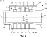
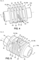
- the bearing thus comprises a pivot 14 as shown in figures 3 and following. More particularly, the figure 3 represents the pivot 14 in its entirety comprising a first annular part 14a and a second annular part 14b. The figure 4 represents the first annular part 14a in isolation.
- the second annular part 14b externally surrounds the first annular part 14a.
- the first annular part 14a comprises an annular wall 15 connected at its ends to two tubular portions 16.
- the annular wall 15 and the tubular portions 16 together internally delimit an axial passage 17.
- This passage is tubular and is coaxial with the axis Y of the pivot.
- the first annular part 14a comprises a plurality of annular grooves G1, G2, G3, G4, G5 along the longitudinal axis Y of the pivot 14.
- the annular grooves G1, G2, G3, G4, G5 are delimited laterally by radial annular partitions 18.
- the partitions radial annular grooves 18, with the exception of the longitudinal end partitions 18a, 18b, comprise openings 19, such as slots, allowing the passage of oil from one annular groove to the other.
- the first annular part 14a comprises an odd number of grooves, i.e. 2k+1 annular grooves, with k a positive integer. It could also comprise an even number of annular grooves.
- the first annular part comprises 5 annular grooves, namely a first annular groove G1 with a longitudinal end, a second annular groove G2, a third annular groove G3, a fourth annular groove G4 and a fifth annular groove G5 with a longitudinal end.
- the second annular part 14b comprises a cylindrical wall 21 mounted in a sealed manner (sealed assembly) around the first annular part 14a so that a radially internal cylindrical surface of this cylindrical wall 21 closes the annular grooves G1, G2, G3, G4, G5 by bearing on the radially external ends of the radial annular partitions 18.
- the annular grooves G1, G2, G3, G4, G5 are in fluid communication with each other so as to form an oil circuit between the first annular part 14a and the second annular part 14b.
- the first annular part 14a comprises at least one oil inlet 20 for cooling the pivot 14.
- it comprises a plurality of oil inlet orifices 20 substantially aligned circumferentially, these orifices 20 opening radially inwards into the axial passage and being able to be fluidically connected to the channels 10d previously described.
- These oil inlet orifices open into the third annular groove G3.
- Each annular groove G1, G2, G3, G4, G5 comprises a radial wall 22 or a wall element 24 joining two consecutive partitions so as to prevent the circulation of oil over 360°, each radial wall 22 or wall element 24 circumferentially separating a first circumferential end of the annular groove and a second circumferential end of the annular groove ( Figures 4 and 5 ).
- the wall element 24 extends over a greater angular distance and houses an oil flow channel 26 whose upstream end is connected to the second circumferential end of the first annular groove G1 and the fifth annular groove G5 and whose downstream end is connected to an oil outlet 28 formed in the cylindrical wall 21 of the second annular part 14b ( figure 6 ).
- Each annular groove G1, G2, G3, G4, G5 comprises an oil inlet at its first circumferential end and an oil outlet at its second circumferential end. More particularly, the oil inlet in the third annular groove G3 is formed by the orifices 20 formed at the first circumferential end of the third annular groove G3.
- This third annular groove G3 comprises two oil outlets arranged at its second circumferential end, a first being formed by an opening 19 for supplying oil to the first circumferential end of the second annular groove G2 and by an opening 19 for supplying oil to the first circumferential end of the fourth annular groove G4. The oil then flows over 360° to the second end of the second annular groove G2 and to the second circumferential end of the fourth annular groove G4.
- FIG 7 illustrates a possible mechanical connection between the first annular part 14a and the second annular part 14b to allow axial locking of the two annular parts together.
- This axial locking can be achieved by the presence of an annular rim 30 extending radially inwards from the cylindrical wall 21 of the second annular part and which is engaged in an annular groove 32 of the first annular part 14a.
- Other locking means can be envisaged such as screwing or welding.
- a rotational locking of the first annular part 14a and second annular part 14b can be provided and achieved for example by the formation of a notch 34 on a radial annular partition 18, this notch 24 cooperating with a member of the second annular part 14b ( figure 8 ).
Landscapes
- Engineering & Computer Science (AREA)
- General Engineering & Computer Science (AREA)
- Mechanical Engineering (AREA)
- Physics & Mathematics (AREA)
- Fluid Mechanics (AREA)
- Chemical & Material Sciences (AREA)
- Oil, Petroleum & Natural Gas (AREA)
- General Details Of Gearings (AREA)
Claims (7)
- Mechanisches Reduktionsgetriebe für ein Gasturbotriebwerk mit Längsachse, enthaltend einen Kranz und Planetenräder (8), die mit einem Sonnenrad (7) und mit dem Kranz (9) in Eingriff stehen und jeweils frei drehbar um ihre Achse (Y) auf einem Planetenradträger (10) gelagert sind, wobei die Planetenräder (8) dazu ausgelegt sind, sich jeweils über einen Drehzapfen (14) um ihre Achse (Y) drehen, der ein erstes ringförmiges Teil (14a) mit einem axialen Schmierungsdurchlass (17) und ein zweites ringförmiges Teil (14b) umfasst, das um das erste ringförmige Teil (14a) herum angebracht ist, wobei das erste ringförmige Teil (14a) mit dem zweiten ringförmigen Teil (14b) einen Schmierungspfad begrenzt, von dem zumindest ein Öleinlass (20) im Inneren des ersten ringförmigen Teils (14a) in den axialen Durchlass (17) mündet und zumindest ein Ölauslass (28) radial außerhalb des zweiten ringförmigen Teils (14b) mündet,wobei das erste ringförmige Teil (14a) eine Ringwand (15) umfasst, in der eine Vielzahl von Ringnuten (G1, G2, G3, G4, G5) ausgebildet ist, um die herum das zweite ringförmige Teil (14b) abdichtend angebracht ist,wobei die Ringnuten (G1, G2, G3, G4, G5) mittels Öffnungen (19), wie Schlitzen, die in ringförmigen Trennwänden (18) zum Trennen der Ringnuten (G1, G2, G3, G4, G5) ausgebildet sind, strömungstechnisch miteinander in Verbindung stehen,wobei jede Ringnut (G1, G2, G3, G4, G5) eine radiale Wand (22, 24) umfasst, die zwei aufeinanderfolgende Trennwände (18) verbindet, um die Ölströmung über 360° zu verhindern, wobei jede radiale Wand (22, 24) in Umfangsrichtung ein erstes Umfangsende der Ringnut (G1, G2, G3, G4, G5) und ein zweites Umfangsende der Ringnut trennt, wobei jede Ringnut (G1, G2, G3, G4, G5) an ihrem ersten Umfangsende einen Öleinlass und an ihrem zweiten Umfangsende einen Ölauslass aufweist.
- Reduktionsgetriebe nach Anspruch 1,
wobei die Ringnuten (G1, G2, G3, G4, G5) strömungstechnisch in Verbindung miteinander stehen. - Reduktionsgetriebe nach Anspruch 2,
wobei der Öleinlass (20) des Schmierungspfads in eine Ringnut (G1, G2, G3, G4, G5) mündet, die in Längsrichtung auf halber Länge des Drehzapfens (14) positioniert ist. - Reduktionsgetriebe nach einem der Ansprüche 1 bis 3,
enthaltend 2k+1 Ringnuten, wobei k eine positive ganze Zahl, vorzugsweise größer oder gleich 3, ist. - Reduktionsgetriebe nach einem der Ansprüche 1 bis 4,
wobei die beiden Ringnuten (G1, G5) an den Längsenden jeweils einen Ölauslass umfassen, der mit einem Kanal (26) verbunden ist, dessen stromabwärtiges Ende radial außerhalb des zweiten ringförmigen Teils (14b) mündet. - Gasturbotriebwerk für ein Luftfahrzeug mit einem Reduktionsgetriebe (6) nach einem der vorhergehenden Ansprüche, dessen Sonnenrad (7) eine Welle des Verdichters des Turbotriebwerks umgibt und drehfest mit dieser verbunden ist.
- Turbotriebwerk nach dem vorhergehenden Anspruch,
wobei der Kranz fest mit einem Statorgehäuse oder -mantelring verbunden ist.
Applications Claiming Priority (1)
| Application Number | Priority Date | Filing Date | Title |
|---|---|---|---|
| FR2108047A FR3125568B1 (fr) | 2021-07-24 | 2021-07-24 | Pivot pour réducteur mécanique de turbomachine |
Publications (2)
| Publication Number | Publication Date |
|---|---|
| EP4123190A1 EP4123190A1 (de) | 2023-01-25 |
| EP4123190B1 true EP4123190B1 (de) | 2025-01-01 |
Family
ID=77411953
Family Applications (1)
| Application Number | Title | Priority Date | Filing Date |
|---|---|---|---|
| EP22186556.1A Active EP4123190B1 (de) | 2021-07-24 | 2022-07-22 | Mechanisches untersetzungsgetriebe für gasturbomaschinen mit längsachse |
Country Status (3)
| Country | Link |
|---|---|
| US (1) | US11708889B2 (de) |
| EP (1) | EP4123190B1 (de) |
| FR (1) | FR3125568B1 (de) |
Family Cites Families (10)
| Publication number | Priority date | Publication date | Assignee | Title |
|---|---|---|---|---|
| US5102379A (en) * | 1991-03-25 | 1992-04-07 | United Technologies Corporation | Journal bearing arrangement |
| IT1250861B (it) * | 1991-11-12 | 1995-04-21 | Fiat Avio Spa | Riduttore di velocita' epicicloidale atto ad essere inserito nella trasmissione tra una turbina a gas ed il compressore d'aria di un motore aeronautico. |
| JP4057327B2 (ja) * | 2002-03-29 | 2008-03-05 | いすゞ自動車株式会社 | 転がり軸受の給油装置 |
| US7574854B2 (en) * | 2006-01-06 | 2009-08-18 | General Electric Company | Gas turbine engine assembly and methods of assembling same |
| JP2008281191A (ja) * | 2007-04-13 | 2008-11-20 | Nsk Ltd | ラジアル軸受、スラスト軸受、変速機、及びハーフトロイダル型無段変速機 |
| FR2977636B1 (fr) * | 2011-07-06 | 2013-08-09 | Snecma | Dispositif de lubrification d'un palier a roulement inter-arbres de turbopropulseur a double helice |
| US10526909B2 (en) * | 2014-01-20 | 2020-01-07 | United Technologies Corporation | Lightweight journal support pin |
| FR3047284B1 (fr) * | 2016-02-01 | 2018-06-15 | Safran Transmission Systems | Palier de satellite pour un porte-satellite, comportant des moyens de lubrification |
| US10683773B2 (en) * | 2018-05-25 | 2020-06-16 | Pratt & Whitney Canada Corp. | Planetary gearbox having compliant journal bearings |
| FR3100050B1 (fr) * | 2019-08-19 | 2021-07-23 | Safran Aircraft Engines | Dispositif de distribution d’huile d’un palier a roulement de turbomachine d’aeronef |
-
2021
- 2021-07-24 FR FR2108047A patent/FR3125568B1/fr active Active
-
2022
- 2022-07-22 EP EP22186556.1A patent/EP4123190B1/de active Active
- 2022-07-25 US US17/872,239 patent/US11708889B2/en active Active
Also Published As
| Publication number | Publication date |
|---|---|
| US20230023320A1 (en) | 2023-01-26 |
| FR3125568A1 (fr) | 2023-01-27 |
| FR3125568B1 (fr) | 2023-07-14 |
| US11708889B2 (en) | 2023-07-25 |
| EP4123190A1 (de) | 2023-01-25 |
Similar Documents
| Publication | Publication Date | Title |
|---|---|---|
| EP3726031B1 (de) | Mechanisches reduktionsgetriebe für luftfahrzeug-turbotriebwerk | |
| EP3922886B1 (de) | Mechanisches reduktionsgetriebe für turbotriebwerk eines luftfahrzeugs | |
| EP4001619B1 (de) | Mechanisches getriebe einer luftfahrzeug-turbomaschine | |
| EP3705705B1 (de) | Mechanisches reduktionsgetriebe für luftfahrzeug-turbotriebwerk | |
| EP3726097B1 (de) | Mechanisches reduktionsgetriebe für luftfahrzeug-turbotriebwerk | |
| EP4034797B1 (de) | Öldrossel zur notschmierung eines bauteils für ein flugzeugtriebwerk | |
| EP3825580B1 (de) | Versorgung und rückgewinnung von schmieröl in einem mechanischen reduktionsgetriebe für luftfahrzeug-turbotriebwerk | |
| EP3667126B1 (de) | Satellitenträger für ein planetengetriebe | |
| EP4336070B1 (de) | Antriebsanordnung für ein mechanisches reduktionsgetriebe einer turbomaschine eines flugzeugs | |
| EP4151846A1 (de) | Turbomaschine eines luftfahrzeugs | |
| EP4336059B1 (de) | Gleitlager für ein mechanisches reduktionsgetriebe eines turbotriebwerks eines luftfahrzeugs | |
| EP4108899A1 (de) | Satellitenträger für ein untersetzungsgetriebe eines turbotriebwerks eines luftfahrzeugs | |
| EP4033086B1 (de) | Turbotriebwerk für luftfahrzeug mit dreifacher strömung, das mit einem leistungsübertragungsmodul ausgestattet ist | |
| EP4242489B1 (de) | Mechanisches reduktionsgetriebe für flugzeugturbomaschine | |
| EP4123190A1 (de) | Mechanisches untersetzungsgetriebe für gasturbomaschinen mit längsachse | |
| EP4469694B1 (de) | Gleitlager für eine flugzeugturbomaschine | |
| EP4375523A1 (de) | Gleitlager für einen satelliten eines mechanischen reduktionsgetriebes eines turbotriebwerks eines luftfahrzeugs | |
| WO2026003458A1 (fr) | Reducteur mecanique pour une turbomachine d'aeronef | |
| FR3153867A1 (fr) | Reducteur mecanique de turbomachine d’aeronef | |
| FR3166187A1 (fr) | Porte-satellites pour un reducteur mecanique de turbomachine d’aeronef | |
| WO2026003460A1 (fr) | Porte-satellites pour un reducteur mecanique de turbomachine d'aeronef | |
| FR3158540A1 (fr) | Reducteur mecanique pour une turbomachine d’aeronef | |
| FR3097269A1 (fr) | Integration d’un reservoir d’huile a un reducteur mecanique de turbomachine d’aeronef | |
| FR3106384A1 (fr) | Porte-satellites pour un reducteur mecanique de turbomachine d’aeronef |
Legal Events
| Date | Code | Title | Description |
|---|---|---|---|
| PUAI | Public reference made under article 153(3) epc to a published international application that has entered the european phase |
Free format text: ORIGINAL CODE: 0009012 |
|
| STAA | Information on the status of an ep patent application or granted ep patent |
Free format text: STATUS: THE APPLICATION HAS BEEN PUBLISHED |
|
| AK | Designated contracting states |
Kind code of ref document: A1 Designated state(s): AL AT BE BG CH CY CZ DE DK EE ES FI FR GB GR HR HU IE IS IT LI LT LU LV MC MK MT NL NO PL PT RO RS SE SI SK SM TR |
|
| STAA | Information on the status of an ep patent application or granted ep patent |
Free format text: STATUS: REQUEST FOR EXAMINATION WAS MADE |
|
| 17P | Request for examination filed |
Effective date: 20230621 |
|
| RBV | Designated contracting states (corrected) |
Designated state(s): AL AT BE BG CH CY CZ DE DK EE ES FI FR GB GR HR HU IE IS IT LI LT LU LV MC MK MT NL NO PL PT RO RS SE SI SK SM TR |
|
| STAA | Information on the status of an ep patent application or granted ep patent |
Free format text: STATUS: EXAMINATION IS IN PROGRESS |
|
| 17Q | First examination report despatched |
Effective date: 20230921 |
|
| GRAP | Despatch of communication of intention to grant a patent |
Free format text: ORIGINAL CODE: EPIDOSNIGR1 |
|
| STAA | Information on the status of an ep patent application or granted ep patent |
Free format text: STATUS: GRANT OF PATENT IS INTENDED |
|
| INTG | Intention to grant announced |
Effective date: 20240325 |
|
| GRAJ | Information related to disapproval of communication of intention to grant by the applicant or resumption of examination proceedings by the epo deleted |
Free format text: ORIGINAL CODE: EPIDOSDIGR1 |
|
| STAA | Information on the status of an ep patent application or granted ep patent |
Free format text: STATUS: EXAMINATION IS IN PROGRESS |
|
| GRAS | Grant fee paid |
Free format text: ORIGINAL CODE: EPIDOSNIGR3 |
|
| STAA | Information on the status of an ep patent application or granted ep patent |
Free format text: STATUS: GRANT OF PATENT IS INTENDED |
|
| INTC | Intention to grant announced (deleted) | ||
| GRAP | Despatch of communication of intention to grant a patent |
Free format text: ORIGINAL CODE: EPIDOSNIGR1 |
|
| INTG | Intention to grant announced |
Effective date: 20240823 |
|
| GRAA | (expected) grant |
Free format text: ORIGINAL CODE: 0009210 |
|
| STAA | Information on the status of an ep patent application or granted ep patent |
Free format text: STATUS: THE PATENT HAS BEEN GRANTED |
|
| AK | Designated contracting states |
Kind code of ref document: B1 Designated state(s): AL AT BE BG CH CY CZ DE DK EE ES FI FR GB GR HR HU IE IS IT LI LT LU LV MC MK MT NL NO PL PT RO RS SE SI SK SM TR |
|
| REG | Reference to a national code |
Ref country code: GB Ref legal event code: FG4D Free format text: NOT ENGLISH |
|
| REG | Reference to a national code |
Ref country code: CH Ref legal event code: EP |
|
| REG | Reference to a national code |
Ref country code: DE Ref legal event code: R096 Ref document number: 602022009263 Country of ref document: DE |
|
| REG | Reference to a national code |
Ref country code: IE Ref legal event code: FG4D Free format text: LANGUAGE OF EP DOCUMENT: FRENCH |
|
| REG | Reference to a national code |
Ref country code: LT Ref legal event code: MG9D |
|
| REG | Reference to a national code |
Ref country code: NL Ref legal event code: MP Effective date: 20250101 |
|
| REG | Reference to a national code |
Ref country code: AT Ref legal event code: MK05 Ref document number: 1756528 Country of ref document: AT Kind code of ref document: T Effective date: 20250101 |
|
| PG25 | Lapsed in a contracting state [announced via postgrant information from national office to epo] |
Ref country code: NL Free format text: LAPSE BECAUSE OF FAILURE TO SUBMIT A TRANSLATION OF THE DESCRIPTION OR TO PAY THE FEE WITHIN THE PRESCRIBED TIME-LIMIT Effective date: 20250101 |
|
| PG25 | Lapsed in a contracting state [announced via postgrant information from national office to epo] |
Ref country code: FI Free format text: LAPSE BECAUSE OF FAILURE TO SUBMIT A TRANSLATION OF THE DESCRIPTION OR TO PAY THE FEE WITHIN THE PRESCRIBED TIME-LIMIT Effective date: 20250101 |
|
| PG25 | Lapsed in a contracting state [announced via postgrant information from national office to epo] |
Ref country code: PL Free format text: LAPSE BECAUSE OF FAILURE TO SUBMIT A TRANSLATION OF THE DESCRIPTION OR TO PAY THE FEE WITHIN THE PRESCRIBED TIME-LIMIT Effective date: 20250101 |
|
| PG25 | Lapsed in a contracting state [announced via postgrant information from national office to epo] |
Ref country code: ES Free format text: LAPSE BECAUSE OF FAILURE TO SUBMIT A TRANSLATION OF THE DESCRIPTION OR TO PAY THE FEE WITHIN THE PRESCRIBED TIME-LIMIT Effective date: 20250101 |
|
| PG25 | Lapsed in a contracting state [announced via postgrant information from national office to epo] |
Ref country code: IS Free format text: LAPSE BECAUSE OF FAILURE TO SUBMIT A TRANSLATION OF THE DESCRIPTION OR TO PAY THE FEE WITHIN THE PRESCRIBED TIME-LIMIT Effective date: 20250501 Ref country code: NO Free format text: LAPSE BECAUSE OF FAILURE TO SUBMIT A TRANSLATION OF THE DESCRIPTION OR TO PAY THE FEE WITHIN THE PRESCRIBED TIME-LIMIT Effective date: 20250401 |
|
| PG25 | Lapsed in a contracting state [announced via postgrant information from national office to epo] |
Ref country code: HR Free format text: LAPSE BECAUSE OF FAILURE TO SUBMIT A TRANSLATION OF THE DESCRIPTION OR TO PAY THE FEE WITHIN THE PRESCRIBED TIME-LIMIT Effective date: 20250101 |
|
| PG25 | Lapsed in a contracting state [announced via postgrant information from national office to epo] |
Ref country code: PT Free format text: LAPSE BECAUSE OF FAILURE TO SUBMIT A TRANSLATION OF THE DESCRIPTION OR TO PAY THE FEE WITHIN THE PRESCRIBED TIME-LIMIT Effective date: 20250502 Ref country code: LV Free format text: LAPSE BECAUSE OF FAILURE TO SUBMIT A TRANSLATION OF THE DESCRIPTION OR TO PAY THE FEE WITHIN THE PRESCRIBED TIME-LIMIT Effective date: 20250101 |
|
| PG25 | Lapsed in a contracting state [announced via postgrant information from national office to epo] |
Ref country code: BG Free format text: LAPSE BECAUSE OF FAILURE TO SUBMIT A TRANSLATION OF THE DESCRIPTION OR TO PAY THE FEE WITHIN THE PRESCRIBED TIME-LIMIT Effective date: 20250101 Ref country code: GR Free format text: LAPSE BECAUSE OF FAILURE TO SUBMIT A TRANSLATION OF THE DESCRIPTION OR TO PAY THE FEE WITHIN THE PRESCRIBED TIME-LIMIT Effective date: 20250402 |
|
| PG25 | Lapsed in a contracting state [announced via postgrant information from national office to epo] |
Ref country code: AT Free format text: LAPSE BECAUSE OF FAILURE TO SUBMIT A TRANSLATION OF THE DESCRIPTION OR TO PAY THE FEE WITHIN THE PRESCRIBED TIME-LIMIT Effective date: 20250101 |
|
| PG25 | Lapsed in a contracting state [announced via postgrant information from national office to epo] |
Ref country code: CZ Free format text: LAPSE BECAUSE OF FAILURE TO SUBMIT A TRANSLATION OF THE DESCRIPTION OR TO PAY THE FEE WITHIN THE PRESCRIBED TIME-LIMIT Effective date: 20250101 |
|
| PG25 | Lapsed in a contracting state [announced via postgrant information from national office to epo] |
Ref country code: SE Free format text: LAPSE BECAUSE OF FAILURE TO SUBMIT A TRANSLATION OF THE DESCRIPTION OR TO PAY THE FEE WITHIN THE PRESCRIBED TIME-LIMIT Effective date: 20250101 |
|
| REG | Reference to a national code |
Ref country code: DE Ref legal event code: R097 Ref document number: 602022009263 Country of ref document: DE |
|
| PG25 | Lapsed in a contracting state [announced via postgrant information from national office to epo] |
Ref country code: SM Free format text: LAPSE BECAUSE OF FAILURE TO SUBMIT A TRANSLATION OF THE DESCRIPTION OR TO PAY THE FEE WITHIN THE PRESCRIBED TIME-LIMIT Effective date: 20250101 |
|
| PG25 | Lapsed in a contracting state [announced via postgrant information from national office to epo] |
Ref country code: DK Free format text: LAPSE BECAUSE OF FAILURE TO SUBMIT A TRANSLATION OF THE DESCRIPTION OR TO PAY THE FEE WITHIN THE PRESCRIBED TIME-LIMIT Effective date: 20250101 |
|
| PGFP | Annual fee paid to national office [announced via postgrant information from national office to epo] |
Ref country code: DE Payment date: 20250722 Year of fee payment: 4 |
|
| PG25 | Lapsed in a contracting state [announced via postgrant information from national office to epo] |
Ref country code: IT Free format text: LAPSE BECAUSE OF FAILURE TO SUBMIT A TRANSLATION OF THE DESCRIPTION OR TO PAY THE FEE WITHIN THE PRESCRIBED TIME-LIMIT Effective date: 20250101 |
|
| PGFP | Annual fee paid to national office [announced via postgrant information from national office to epo] |
Ref country code: FR Payment date: 20250722 Year of fee payment: 4 |
|
| PG25 | Lapsed in a contracting state [announced via postgrant information from national office to epo] |
Ref country code: EE Free format text: LAPSE BECAUSE OF FAILURE TO SUBMIT A TRANSLATION OF THE DESCRIPTION OR TO PAY THE FEE WITHIN THE PRESCRIBED TIME-LIMIT Effective date: 20250101 |
|
| PG25 | Lapsed in a contracting state [announced via postgrant information from national office to epo] |
Ref country code: RO Free format text: LAPSE BECAUSE OF FAILURE TO SUBMIT A TRANSLATION OF THE DESCRIPTION OR TO PAY THE FEE WITHIN THE PRESCRIBED TIME-LIMIT Effective date: 20250101 |
|
| PG25 | Lapsed in a contracting state [announced via postgrant information from national office to epo] |
Ref country code: SK Free format text: LAPSE BECAUSE OF FAILURE TO SUBMIT A TRANSLATION OF THE DESCRIPTION OR TO PAY THE FEE WITHIN THE PRESCRIBED TIME-LIMIT Effective date: 20250101 |
|
| PLBE | No opposition filed within time limit |
Free format text: ORIGINAL CODE: 0009261 |
|
| STAA | Information on the status of an ep patent application or granted ep patent |
Free format text: STATUS: NO OPPOSITION FILED WITHIN TIME LIMIT |
|
| REG | Reference to a national code |
Ref country code: CH Ref legal event code: L10 Free format text: ST27 STATUS EVENT CODE: U-0-0-L10-L00 (AS PROVIDED BY THE NATIONAL OFFICE) Effective date: 20251112 |
|
| 26N | No opposition filed |
Effective date: 20251002 |
|
| REG | Reference to a national code |
Ref country code: CH Ref legal event code: H13 Free format text: ST27 STATUS EVENT CODE: U-0-0-H10-H13 (AS PROVIDED BY THE NATIONAL OFFICE) Effective date: 20260224 |
|
| PG25 | Lapsed in a contracting state [announced via postgrant information from national office to epo] |
Ref country code: LU Free format text: LAPSE BECAUSE OF NON-PAYMENT OF DUE FEES Effective date: 20250722 |
|
| REG | Reference to a national code |
Ref country code: BE Ref legal event code: MM Effective date: 20250731 |
|
| PG25 | Lapsed in a contracting state [announced via postgrant information from national office to epo] |
Ref country code: BE Free format text: LAPSE BECAUSE OF NON-PAYMENT OF DUE FEES Effective date: 20250731 |
|
| PG25 | Lapsed in a contracting state [announced via postgrant information from national office to epo] |
Ref country code: CH Free format text: LAPSE BECAUSE OF NON-PAYMENT OF DUE FEES Effective date: 20250731 |
|
| PG25 | Lapsed in a contracting state [announced via postgrant information from national office to epo] |
Ref country code: LT Free format text: LAPSE BECAUSE OF FAILURE TO SUBMIT A TRANSLATION OF THE DESCRIPTION OR TO PAY THE FEE WITHIN THE PRESCRIBED TIME-LIMIT Effective date: 20250101 |
|
| PG25 | Lapsed in a contracting state [announced via postgrant information from national office to epo] |
Ref country code: RS Free format text: LAPSE BECAUSE OF FAILURE TO SUBMIT A TRANSLATION OF THE DESCRIPTION OR TO PAY THE FEE WITHIN THE PRESCRIBED TIME-LIMIT Effective date: 20250101 |
|
| PG25 | Lapsed in a contracting state [announced via postgrant information from national office to epo] |
Ref country code: IE Free format text: LAPSE BECAUSE OF NON-PAYMENT OF DUE FEES Effective date: 20250722 |
|
| PG25 | Lapsed in a contracting state [announced via postgrant information from national office to epo] |
Ref country code: MC Free format text: LAPSE BECAUSE OF FAILURE TO SUBMIT A TRANSLATION OF THE DESCRIPTION OR TO PAY THE FEE WITHIN THE PRESCRIBED TIME-LIMIT Effective date: 20250101 |
|
| PG25 | Lapsed in a contracting state [announced via postgrant information from national office to epo] |
Ref country code: CY Free format text: LAPSE BECAUSE OF FAILURE TO SUBMIT A TRANSLATION OF THE DESCRIPTION OR TO PAY THE FEE WITHIN THE PRESCRIBED TIME-LIMIT Effective date: 20250101 |