EP4123231A1 - Frischluftmodul und klimaanlage - Google Patents
Frischluftmodul und klimaanlage Download PDFInfo
- Publication number
- EP4123231A1 EP4123231A1 EP20928498.3A EP20928498A EP4123231A1 EP 4123231 A1 EP4123231 A1 EP 4123231A1 EP 20928498 A EP20928498 A EP 20928498A EP 4123231 A1 EP4123231 A1 EP 4123231A1
- Authority
- EP
- European Patent Office
- Prior art keywords
- fresh air
- motor
- housing
- wind wheel
- air outlet
- Prior art date
- Legal status (The legal status is an assumption and is not a legal conclusion. Google has not performed a legal analysis and makes no representation as to the accuracy of the status listed.)
- Granted
Links
Images


Classifications
-
- F—MECHANICAL ENGINEERING; LIGHTING; HEATING; WEAPONS; BLASTING
- F24—HEATING; RANGES; VENTILATING
- F24F—AIR-CONDITIONING; AIR-HUMIDIFICATION; VENTILATION; USE OF AIR CURRENTS FOR SCREENING
- F24F1/00—Room units for air-conditioning, e.g. separate or self-contained units or units receiving primary air from a central station
- F24F1/0007—Indoor units, e.g. fan coil units
- F24F1/0018—Indoor units, e.g. fan coil units characterised by fans
-
- F—MECHANICAL ENGINEERING; LIGHTING; HEATING; WEAPONS; BLASTING
- F24—HEATING; RANGES; VENTILATING
- F24F—AIR-CONDITIONING; AIR-HUMIDIFICATION; VENTILATION; USE OF AIR CURRENTS FOR SCREENING
- F24F1/00—Room units for air-conditioning, e.g. separate or self-contained units or units receiving primary air from a central station
- F24F1/0007—Indoor units, e.g. fan coil units
- F24F1/0011—Indoor units, e.g. fan coil units characterised by air outlets
-
- F—MECHANICAL ENGINEERING; LIGHTING; HEATING; WEAPONS; BLASTING
- F24—HEATING; RANGES; VENTILATING
- F24F—AIR-CONDITIONING; AIR-HUMIDIFICATION; VENTILATION; USE OF AIR CURRENTS FOR SCREENING
- F24F1/00—Room units for air-conditioning, e.g. separate or self-contained units or units receiving primary air from a central station
- F24F1/0007—Indoor units, e.g. fan coil units
- F24F1/0035—Indoor units, e.g. fan coil units characterised by introduction of outside air to the room
-
- F—MECHANICAL ENGINEERING; LIGHTING; HEATING; WEAPONS; BLASTING
- F24—HEATING; RANGES; VENTILATING
- F24F—AIR-CONDITIONING; AIR-HUMIDIFICATION; VENTILATION; USE OF AIR CURRENTS FOR SCREENING
- F24F1/00—Room units for air-conditioning, e.g. separate or self-contained units or units receiving primary air from a central station
- F24F1/0007—Indoor units, e.g. fan coil units
- F24F1/0043—Indoor units, e.g. fan coil units characterised by mounting arrangements
- F24F1/0057—Indoor units, e.g. fan coil units characterised by mounting arrangements mounted in or on a wall
-
- F—MECHANICAL ENGINEERING; LIGHTING; HEATING; WEAPONS; BLASTING
- F24—HEATING; RANGES; VENTILATING
- F24F—AIR-CONDITIONING; AIR-HUMIDIFICATION; VENTILATION; USE OF AIR CURRENTS FOR SCREENING
- F24F1/00—Room units for air-conditioning, e.g. separate or self-contained units or units receiving primary air from a central station
- F24F1/0007—Indoor units, e.g. fan coil units
- F24F1/0071—Indoor units, e.g. fan coil units with means for purifying supplied air
- F24F1/0073—Indoor units, e.g. fan coil units with means for purifying supplied air characterised by the mounting or arrangement of filters
-
- F—MECHANICAL ENGINEERING; LIGHTING; HEATING; WEAPONS; BLASTING
- F24—HEATING; RANGES; VENTILATING
- F24F—AIR-CONDITIONING; AIR-HUMIDIFICATION; VENTILATION; USE OF AIR CURRENTS FOR SCREENING
- F24F13/00—Details common to, or for air-conditioning, air-humidification, ventilation or use of air currents for screening
- F24F13/02—Ducting arrangements
-
- F—MECHANICAL ENGINEERING; LIGHTING; HEATING; WEAPONS; BLASTING
- F24—HEATING; RANGES; VENTILATING
- F24F—AIR-CONDITIONING; AIR-HUMIDIFICATION; VENTILATION; USE OF AIR CURRENTS FOR SCREENING
- F24F13/00—Details common to, or for air-conditioning, air-humidification, ventilation or use of air currents for screening
- F24F13/20—Casings or covers
-
- F—MECHANICAL ENGINEERING; LIGHTING; HEATING; WEAPONS; BLASTING
- F24—HEATING; RANGES; VENTILATING
- F24F—AIR-CONDITIONING; AIR-HUMIDIFICATION; VENTILATION; USE OF AIR CURRENTS FOR SCREENING
- F24F13/00—Details common to, or for air-conditioning, air-humidification, ventilation or use of air currents for screening
- F24F13/24—Means for preventing or suppressing noise
-
- F—MECHANICAL ENGINEERING; LIGHTING; HEATING; WEAPONS; BLASTING
- F24—HEATING; RANGES; VENTILATING
- F24F—AIR-CONDITIONING; AIR-HUMIDIFICATION; VENTILATION; USE OF AIR CURRENTS FOR SCREENING
- F24F8/00—Treatment, e.g. purification, of air supplied to human living or working spaces otherwise than by heating, cooling, humidifying or drying
- F24F8/10—Treatment, e.g. purification, of air supplied to human living or working spaces otherwise than by heating, cooling, humidifying or drying by separation, e.g. by filtering
-
- F—MECHANICAL ENGINEERING; LIGHTING; HEATING; WEAPONS; BLASTING
- F24—HEATING; RANGES; VENTILATING
- F24F—AIR-CONDITIONING; AIR-HUMIDIFICATION; VENTILATION; USE OF AIR CURRENTS FOR SCREENING
- F24F13/00—Details common to, or for air-conditioning, air-humidification, ventilation or use of air currents for screening
- F24F13/20—Casings or covers
- F24F2013/205—Mounting a ventilator fan therein
-
- F—MECHANICAL ENGINEERING; LIGHTING; HEATING; WEAPONS; BLASTING
- F24—HEATING; RANGES; VENTILATING
- F24F—AIR-CONDITIONING; AIR-HUMIDIFICATION; VENTILATION; USE OF AIR CURRENTS FOR SCREENING
- F24F13/00—Details common to, or for air-conditioning, air-humidification, ventilation or use of air currents for screening
- F24F13/24—Means for preventing or suppressing noise
- F24F2013/247—Active noise-suppression
Definitions
- the present application relates to the field of air conditioning, and in particular to a fresh air module and an air conditioner.
- the air conditioners on the market are usually provided with fresh air modules, and fresh air of the outdoors can be introduced into the indoors by the fresh air modules, to replenish the amount of fresh air of the indoors and improve the air quality of the indoors.
- a wind wheel assembly is usually needed to be configured in the fresh air module to guide the airflow to the indoors from the outdoors.
- the operation of the motor in the wind wheel assembly generates noise, and the noise is amplified by the airflow in the fresh air duct and enters the indoors.
- the main objective of the present application is to provide a fresh air module and an air conditioner including the fresh air module, which aim to reduce the noise generated by the fresh air module.
- a fresh air module which includes:
- the motor cover is provided on and extended from an outer wall of the housing to locate the motor accommodating cavity outside of the fresh air duct.
- the fresh air module further includes a purification assembly disposed in the fresh air duct and located between the fresh air inlet and the fresh air outlet, to enable the airflow flows through the purification assembly.
- the purification assembly is located at one side of the wind wheel in an axial direction of the wind wheel to correspond to an air inlet side of the wind wheel.
- the fresh air module further includes a middle partition plate disposed in the fresh air duct and located at the air inlet side of the wind wheel, the middle partition plate is provided with a ventilation opening corresponding to the air inlet side of the wind wheel, and the purification assembly is of a pull-push type, mounted on the middle partition plate and located on an air inlet side of the ventilation opening.
- the housing includes a bottom housing and a cover
- the bottom housing is provided with a front side facing a first direction and a rear side facing away from the first direction
- the front side of the bottom housing is provided with an opening
- the cover covers the front side of the bottom housing
- the middle partition plate is arranged between the bottom housing and the cover
- the fresh air duct comprises an air inlet cavity and an air outlet cavity
- the air inlet cavity is formed between the cover and the middle partition plate
- the air outlet cavity is formed between the middle partition plate and the bottom housing
- the wind wheel is arranged in the air outlet cavity.
- the motor cover is provided on and extends from the rear side of the bottom housing, and the motor shaft is started from the motor body and extends into the air outlet cavity along the first direction to connect with the wind wheel.
- the motor cover is integrally formed with the bottom housing, a mounting opening is formed on the bottom housing, the motor accommodating cavity is communicated with the air outlet cavity through the mounting opening, and the partition member covers the mounting opening.
- the bottom housing is provided with a plurality of studs with openings facing the first direction, the plurality of studs are distributed at intervals in a circumferential direction of the mounting opening, a plurality of screws are arranged on the partition member, and each screw is screwed to the corresponding stud to fix the partition member to the bottom housing.
- a plurality of accommodating housings are arranged on a peripheral side of the motor cover, distributed at intervals in a circumferential direction of the motor cover, and integrally formed with the motor cover, an accommodating groove is formed in each accommodating housing and extends in the first direction, and each stud is arranged in the corresponding accommodating groove.
- a plurality of positioning ribs are provided on and extended from the bottom housing and distributed at intervals along a circumferential direction of the mounting opening, a plurality of notches are formed at a peripheral side of the partition member, and each positioning rib is inserted in the corresponding notch.
- a lower side of the motor cover is provided with a wiring port.
- water baffles are provided on and extend from an outer wall of the motor cover, and the water baffles are distributed on a periphery of the wiring port for shielding water flows flowing to the wiring port.
- a wire groove rib is provided on and extends from the rear side of the bottom housing, the wire groove rib and the bottom housing cooperates to form a wire groove extending along a wiring direction for accommodating a wire headed from the wiring port, the wire groove is bent along an extension direction thereof to form a water collecting elbow, and the water collecting elbow is arranged to avoid electronic components.
- a first rubber gasket is arranged between the motor body and the partition member, a second rubber gasket is arranged between the motor body and the motor cover, and the first rubber gasket and the second rubber gasket are respectively distributed at two ends of the motor body in an extension direction of the motor shaft, to limit the motor body in the extension direction of the motor shaft.
- annular step groove is formed on each of the partition member and the motor cover, and each of the first rubber gasket and the second rubber gasket is accommodated in a corresponding annular step groove to limit the motor body in a radial direction of the motor shaft.
- the present application further provides an air conditioner, which includes:
- the air conditioner is any one of an indoor unit of a wall-mounted air conditioner, an indoor unit of a cabinet air conditioner, an air machine, an indoor unit of a ceiling type air conditioner or a mobile air conditioner.
- the air conditioner is the indoor unit of the wall-mounted air conditioner
- the housing of the air conditioner includes a chassis, a frame and a panel
- the fresh air module is mounted at an end of the chassis
- the fresh air outlet of the fresh air module faces toward the panel
- the panel is provided with the second air outlet corresponding to the fresh air outlet.
- the motor cover is arranged outside the housing and located outside the fresh air duct.
- a motor accommodating cavity is formed in the motor cover and accommodates the motor body.
- a partition member is arranged between the motor accommodating cavity and the fresh air duct to separate the motor accommodating cavity from the fresh air duct.
- the motor shaft penetrates through the partition member and is connected to the wind wheel for driving the wind wheel.
- the motor body is arranged outside the fresh air duct and is isolated from the fresh air duct through the partition member, and thus the noise amplification effect of the air cavity is avoided, and the noise generated by the fresh air module is reduced.
- the present application provides embodiments of a fresh air module and an air conditioner including the fresh air module.
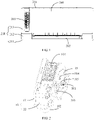
- the dotted arrow in FIG. 5 indicates an airflow direction.
- the air conditioner may be an indoor unit of a wall-mounted air conditioner, or an indoor unit of a cabinet air conditioner, or an air machine, or an indoor unit of a ceiling type air conditioner or a mobile air conditioner.
- the indoor unit of the wall-mounted air conditioner is taken as an example for illustration, and provides reference for other types of air conditioner.
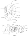
- the fresh air module includes a housing 10, a fan assembly and a motor cover 30.
- the housing 10 is provided with a fresh air inlet 102 and a fresh air outlet 103.
- the housing 10 is provided with a fresh air duct 101 inside.
- the fresh air duct 101 communicates with the fresh air inlet 102 and the fresh air outlet 103.
- the fan assembly includes a motor and a wind wheel 60.
- the wind wheel 60 is received in the fresh air duct 101.
- the motor includes a motor body 32 and a motor shaft 31.
- the motor shaft 31 is connected to the wind wheel 60 to drive the wind wheel 60 to rotate and thereby to drive air to enter the fresh air duct 101 from the fresh air inlet 102 and exit from the fresh air outlet 103.
- the motor cover 30 is disposed on the housing 10 and located outside the fresh air duct 101.
- a motor accommodating cavity is formed inside the motor cover 30, and the motor body 32 is disposed in the motor accommodating cavity.
- a partition member 40 is disposed between the motor accommodating cavity and the fresh air duct 101, to separate the motor accommodating cavity from the fresh air duct 101.
- the motor shaft 31 passes through the partition member 40 to connect to the wind wheel 60 and drive the wind wheel 60.
- the fresh air inlet 102 may be provided at a bottom of the housing 10 of the fresh air module, and the fresh air outlet 103 may be provided at a top, a front side, a left side or a right side of the fresh air module, and the positions of the fresh air inlet 102 and the fresh air outlet 103 can be designed according to the types of the air conditioners employing the fresh air module in practical applications.
- the fresh air inlet 102 can be provided at the bottom of the housing 10, and the fresh air outlet 103 can be provided at a side of the housing 10.
- the fresh air inlet 102 and the fresh air outlet 103 are distributed in different radial directions of the fan assembly. Referring to FIG.
- the fan assembly when the fresh air module works, the fan assembly is turned on, and the fan assembly drives fresh air to enter the fresh air duct 101 from the fresh air inlet 102.
- the fresh air flows to an air inlet side of the wind wheel 60 firstly, and then flows from an air outlet side of the wind wheel 60 to the fresh air outlet 103 and is blown out from the fresh air outlet 103.
- the motor includes the motor body 32 and the motor shaft 31.
- the motor body 32 is provided with a component for driving the motor shaft 31 to rotate. Air noise, mechanical noise, electromagnetic noise and the like are generated during the operation of the motor.
- the motor is located in the air duct and the air duct diffuses the noises and amplifies the noises.
- the motor cover 30 is located outside the fresh air duct 101, and a partition member 40 is provided between the motor accommodating cavity and the fresh air duct 101, thereby the motor accommodating cavity and the fresh air duct 101 are spaced apart from each other.
- the motor shaft 31 passes through the partition member 40 and is connected to the wind wheel 60 to drive the wind wheel 60.
- the motor body 32 is disposed outside the fresh air duct 101 and isolated from the fresh air duct 101 by the partition member 40, the amplification of the noise by the air cavity is avoided, and the noise generated by the fresh air module is reduced.
- the motor cover 30 is disposed on the housing 10, and the motor cover 30 may protrude beyond an outer wall of the housing 10, or be disposed in the housing 10, so long as the motor cover 30 is located outside the fresh air duct 101.
- the motor cover 30 may be disposed separately from the housing 10, or may be integrally formed with the housing 10, or may be configured as a part of the housing 10. It can be understood that when the motor cover 30 is located in the housing 10, the motor is prone to driving the housing 10 to vibrate and generate noise during working, and for the solid transmits sound faster, the noise is amplified.
- the motor cover 30 is protruded over the outer wall of the housing 10, which makes the motor accommodating cavity located outside of the fresh air duct 101.
- the fresh air module in the present application further includes a purification assembly 20.
- the purification assembly 20 is disposed in the fresh air duct 101 and located between the fresh air inlet 102 and the fresh air outlet 103, such that the airflow flows through the purification assembly 20.
- the purification assembly 20 includes a mounting frame and a purifying member mounted on the mounting frame.
- the purifying member may be adapted to remove any one or more types of air pollutant such as dust, fine particulate matter, microorganisms, and organic volatile gases such as formaldehyde in the air.
- the specific type of the purifying member may be selected according to the function thereof, and the purifying member may be any one or a combination of two or more of a conventional filter screen, a HEPA screen or an IFD filter, or be any one or a combination of one or more of a primary efficiency filter screen, a medium efficiency filter screen, and a high efficiency filter screen. In this way, fresh air flowing into the indoors can be purified, which is good for improving the air quality of the indoors.
- the purification assembly 20 is located at one side of the wind wheel 60 in an axial direction thereof, to correspond to the air inlet side of the wind wheel 60.
- the air enters the wind wheel 60 along the axial direction of the wind wheel 60 and exits the wind wheel 60 along an radial direction of the wind wheel 60.
- a larger air inlet surface is formed at the air inlet side of the fan assembly, and thus a relatively large air inlet space is formed at the air inlet side of the fan assembly.
- the purification assembly 20 is arranged to correspond to the air inlet side of the fan assembly, a purification surface of the purification assembly 20, which is provided for the air to pass through and be purified, can be set to be larger, and the efficiency of the purification assembly 20 to purify the air is improved.
- the purification assembly 20 is correspondingly set to be relatively large, the amount of air that can be purified by the purification assembly 20 is correspondingly increased, the service life of the purification assembly 20 is accordingly prolonged and it takes a longer period before a new purification assembly 20 is needed.
- the fresh air module further includes a middle partition plate 13 disposed in the fresh air duct 101 and located at the air inlet side of the wind wheel 60.
- the middle partition plate 13 is provided with a ventilation opening 130 corresponding to the air inlet side of the wind wheel 60.
- the purification assembly 20 is of a push-pull type and mounted on the middle partition plate 13, and the purification assembly 20 is located on an air inlet side of the ventilation opening 130. As such, when the purification assembly 20 is in an idle state, the purification assembly 20 may be cleaned or be replaced with a new one. The user can pull the purification assembly 20 by hand, disassemble the purification assembly 20 and replace the purification assembly 20 with a new one, which is simple and easy to operate.
- the housing 10 includes a bottom housing 11 and a cover 12.
- the bottom housing 11 has a front side facing a first direction and a rear side facing away from the first direction.
- the front side of the bottom housing 11 is provided with an opening, and the cover 12 covers the front side of the bottom housing 11.
- the middle partition plate 13 is disposed between the bottom housing 11 and the cover 12.
- An air inlet cavity 1011 is formed between the cover 12 and the middle partition plate 13, and an air outlet cavity 1012 is formed between the middle partition plate 13 and the bottom housing 11.
- the wind wheel 60 is disposed in the air outlet cavity 1012.
- the wind wheel 60 is arranged in the air outlet cavity 1012, and the purification assembly 20 prevents impurities such as dust from entering the air outlet cavity 1012, the wind wheel 60 located in the air outlet cavity 1012 is not affected by the impurities, the service life of the wind wheel 60 is prolonged, and the wind wheel 60 can be conveniently cleaned. Furthermore, the arranging of the bottom housing 11 and the cover 12 facilitates the assembling of the fresh air module.
- the motor cover 30 is arranged on and extends from the rear side of the bottom housing 11, thereby the motor shaft 31 is extended into the air outlet cavity 1012 from the motor body 32 along the first direction, and connected to the wind wheel 60 to drive the wind wheel 60.
- both the motor and the wind wheel 60 are located on a side part of the housing 10 where the air outlet cavity 1012 is located, and the installation is facilitated, and an axis of the wind wheel 60 is prevented from passing through the air inlet cavity 1011.
- the motor cover 30 can be integrally formed with the bottom housing 11.
- a mounting opening is formed on the bottom housing 11, and the motor accommodating cavity is communicated with the air outlet cavity 1012 through the mounting opening.
- the partition member 40 covers the mounting opening. In this way, when to assemble the fresh air module, the operator only needs to install the motor and the wind wheel 60 in the first direction, and does not need to change between the front side and the rear side of the bottom housing 11 in the installation process. Thus the assembling efficiency is improved.
- the motor cover 30 is integrally formed with the bottom housing 11, there is no relative displacement between the motor cover 30 and the bottom housing 11, and the situation that the motor cover 30 and the bottom housing 11 collide with each other and generate noise under the vibration of the motor is avoided, and thus the noise of the fresh air module during working is further reduced.
- the bottom housing 11 is provided with a plurality of studs 41 with openings facing the first direction, and the plurality of studs 41 are distributed at intervals along a circumferential direction of the mounting opening.
- the partition member 40 are provided with a plurality of screws, and the screws are screwed to the studs 41 correspondingly, to fix the partition member 40 to the bottom housing 11.
- the partition member 40 is fixed by the cooperation of the screws and the studs 41, and meanwhile the motor body 32 is also fixed in the motor accommodating cavity.
- an engagement area between the screws and the studs 41 is larger, and the friction force therebetween is larger.
- the openings of the studs 41 all face the first direction, which facilitates the operation of the operator in the first direction, and improves the installation efficiency.
- a plurality of accommodating housings 304 are arranged on a peripheral side of the motor cover 30 and distributed at intervals in a circumferential direction of the motor cover 30.
- the accommodating housings 304 are integrally formed with the motor cover 30.
- An accommodating groove is formed in each accommodating housing 304 and extended in the first direction, and the studs 41 are arranged in the accommodating grooves.
- the studs 41 are structurally stronger, noise is not easily generated due to shaking, the appearance is simple and the molding is facilitated.
- a plurality of positioning ribs are arranged on and extend from the bottom housing 11 and distributed at intervals along the circumferential direction of the mounting opening.
- a plurality of notches 42 are formed in a peripheral side of the partition member 40, and the positioning ribs are inserted into the notches 42 correspondingly.
- a wiring port 301 is provided at a lower side of the motor cover 30 for a wire, which is connected to the motor body 32, to pass through.
- the motor needs to be connected with an external electronic device through a power line or a signal line, and thus the wiring port 301 is needed to be formed on the motor cover 30.
- the fresh air module introduces the air from the outdoors, when the air conditioner is in a refrigeration state, a temperature of the outdoors is high, and a temperature of the indoors is low. Water tends to condense on outer surfaces of the housing 10 and the motor cover 30. When the fresh air module is adjacent to or located in a heat exchange air duct, more water condenses.
- Water may also condense on surfaces inside the air conditioner. If the condensed water flows into the motor cavity, the motor may be damaged.
- the wiring port 301 is located on the lower side of the motor cover 30, to prevent external condensed water from being directly falling into the wiring port 301 and causing the dampening and damage of the motor.
- water baffles 302 are provided on and extend from an outer wall of the motor cover 30, and the water baffles 302 are distributed on a periphery of the wiring port 301 for shielding water flows flowing to the wiring port 301. In this way, condensed water flowing along the surface of the motor cover 30 is prevented from flowing into the wiring port 301 and resulting in dampening and damage of the motor.
- the rear side of the bottom housing 11 is provided with a wire groove rib 303 extending from the rear side.
- the wire groove rib 303 and the bottom housing 11 cooperate to form a wire groove.
- the wire groove is extended along a wiring direction and configured for accommodating the wire headed from the wiring port.
- the wire groove is bent along an extension direction to form a water collecting elbow 3031, and the water collecting elbow 3031 is arranged to avoid electronic components in the air conditioner.
- a first rubber gasket 51 is arranged between the motor body 32 and the partition member 40
- a second rubber gasket 52 is arranged between the motor body 32 and the motor cover 30, and the first rubber gasket 51 and the second rubber gasket 52 are respectively distributed at two ends of the motor body 32 in an extension direction of the motor shaft 31, to limit the motor body 32 in the extension direction of the motor shaft 31.
- the motor is fixed in the motor cover 30 through the first rubber gasket 51 and the second rubber gasket 52. Due to certain elasticity possessed by the rubber, the vibration of the motor can be effectively absorbed, and the noise generated by the motor during working is reduced.
- each of the partition member 40 and the motor cover 30 is formed with an annular step groove, and each of the first rubber gasket 51 and the second rubber gasket 52 is accommodated in a corresponding annular step groove, to limit the motor body 32 in the radial direction of the motor shaft 31.
- the motor body 32 is effectively limited in the axial direction and the radial direction of the motor shaft 31, and the installation thereof is more secure. Further, the motor body 32 is prevented from directly contacting with the partition member 40 and the motor cover 30 with higher hardness, the installation gap is smaller, and the noise generated by vibration in the working process is reduced.
- the present application further provides an air conditioner.
- the air conditioner includes a housing 200 and a fresh air module mounted in the housing 200.
- the detailed structure of the fresh air module refers to the above embodiment. Since the air conditioner adopts all the technical solutions of all the above embodiments, the air conditioner at least possesses the beneficial effects brought by the technical solutions of the above embodiments, which will not be repeated here.
- the air conditioner is any one of an indoor unit of a wall-mounted air conditioner, an indoor unit of a cabinet air conditioner, an air machine, an indoor unit of a ceiling type air conditioner or a mobile air conditioner.
- the indoor unit of the wall-mounted air conditioner is taken as an example for illustration in the following.
- the housing 200 is provided with an air inlet 201, a first air outlet 202 and a second air outlet 203.
- the air inlet 201 is in communication with the first air outlet 202.
- the fresh air module is mounted in the housing 200, the fresh air inlet 102 of the fresh air module is adapted to communicate with the outdoors through a fresh air tube, and the fresh air outlet 103 of the fresh air module is adapted to communicate with the second air outlet 203.
- the air conditioner has an indoor air circulation mode and a fresh air mode.
- the indoor air enters the housing 200 through the air inlet 201, cold air or hot air is generated after heat exchange by a heat exchange assembly inside the housing 200, and then the cold air or hot air is blown back to the indoors from the first air outlet 202 to realize the indoor air circulation.
- the outdoor air enters the fresh air module through the fresh air tube, and clean fresh air is generated after purification by the purification assembly of the fresh air module.
- the fresh air is blown to the second air outlet 203 of the housing 200 from the fresh air outlet 103 of the fresh air module, and finally blown to the indoors from the second air outlet 203, to replenish the fresh air of the indoors.
- the housing 200 includes a chassis 211, a frame 212 and a panel 213.
- the fresh air module is mounted at an end of the chassis 211.
- the fresh air outlet 103 of the fresh air module faces toward the panel 213. Accordingly, the panel 213 is provided with the second air outlet 203 corresponding to the fresh air outlet 103, so that the fresh air is output by the air conditioner and accurately reaches where the user stays.
- the second air outlet 203 may be set to consist of a plurality of micropores penetrating through the panel 213. Therefore, after the fresh air is blown out from the plurality of micropores, the airflow is divided into small airflows with a smaller diameter, the speed of the airflows is reduced, the airflows become soft, and are not directly blown to the user, which avoids causing discomfort to the user.
Landscapes
- Engineering & Computer Science (AREA)
- Chemical & Material Sciences (AREA)
- Combustion & Propulsion (AREA)
- Mechanical Engineering (AREA)
- General Engineering & Computer Science (AREA)
- Air-Conditioning For Vehicles (AREA)
- Air-Flow Control Members (AREA)
- Motor Or Generator Frames (AREA)
- External Artificial Organs (AREA)
Applications Claiming Priority (2)
| Application Number | Priority Date | Filing Date | Title |
|---|---|---|---|
| CN202010241374.8A CN111306635B (zh) | 2020-03-30 | 2020-03-30 | 新风模块与空调器 |
| PCT/CN2020/129246 WO2021196635A1 (zh) | 2020-03-30 | 2020-11-17 | 新风模块与空调器 |
Publications (3)
| Publication Number | Publication Date |
|---|---|
| EP4123231A1 true EP4123231A1 (de) | 2023-01-25 |
| EP4123231A4 EP4123231A4 (de) | 2023-09-06 |
| EP4123231B1 EP4123231B1 (de) | 2024-08-14 |
Family
ID=71146023
Family Applications (1)
| Application Number | Title | Priority Date | Filing Date |
|---|---|---|---|
| EP20928498.3A Active EP4123231B1 (de) | 2020-03-30 | 2020-11-17 | Frischluftmodul und klimaanlage |
Country Status (5)
| Country | Link |
|---|---|
| US (1) | US11953227B2 (de) |
| EP (1) | EP4123231B1 (de) |
| CN (1) | CN111306635B (de) |
| AU (1) | AU2020440785B2 (de) |
| WO (1) | WO2021196635A1 (de) |
Families Citing this family (6)
| Publication number | Priority date | Publication date | Assignee | Title |
|---|---|---|---|---|
| EP3734180B1 (de) * | 2019-03-03 | 2021-08-18 | GD Midea Air-Conditioning Equipment Co., Ltd. | Frischluftplattenanordnung, klimaanlageninnenraumeinheit und klimaanlage |
| CN111306635B (zh) | 2020-03-30 | 2025-02-28 | 广东美的制冷设备有限公司 | 新风模块与空调器 |
| CN112460787B (zh) * | 2020-11-23 | 2022-05-27 | 珠海格力电器股份有限公司 | 底盘部件及空调器 |
| CN113251478B (zh) * | 2021-05-28 | 2025-06-27 | 珠海格力节能环保制冷技术研究中心有限公司 | 新风部件、排水结构和新风空调 |
| CN113446666A (zh) * | 2021-07-29 | 2021-09-28 | 珠海格力电器股份有限公司 | 新风装置及具有其的空调室内机 |
| CN115597163B (zh) * | 2022-11-11 | 2025-11-14 | 格力电器(杭州)有限公司 | 新风装置及具有其的空调器 |
Family Cites Families (20)
| Publication number | Priority date | Publication date | Assignee | Title |
|---|---|---|---|---|
| US4245965A (en) * | 1979-01-25 | 1981-01-20 | Master Air Inc. | Gas-handling apparatus |
| US5397950A (en) * | 1993-12-23 | 1995-03-14 | Cary Products Co., Inc. | Isolation motor mount and gasket |
| KR200145081Y1 (ko) * | 1995-10-06 | 1999-06-15 | 류정열 | 자동차의 블로우 모터 방음구 |
| GB9521634D0 (en) * | 1995-10-21 | 1996-01-03 | Advanced Design & Mfg Ltd | Ventilation system |
| CN2264320Y (zh) * | 1996-06-21 | 1997-10-08 | 林义涵 | 排油烟机的风扇马达装置 |
| WO2009021356A1 (en) * | 2007-08-13 | 2009-02-19 | Shenzhen Longgang Jinyixin Electronic Factory | Centrifugal air blower and fresh air device having the blower |
| CN202001340U (zh) * | 2011-03-23 | 2011-10-05 | 浙江志江风机有限公司 | 一种离心式屋顶风机 |
| JP2015121392A (ja) * | 2013-12-25 | 2015-07-02 | ダイキン工業株式会社 | 空気調和システム |
| TWI544177B (zh) * | 2014-10-15 | 2016-08-01 | 台達電子工業股份有限公司 | 具有燈具的換氣扇 |
| CN207422515U (zh) * | 2017-08-18 | 2018-05-29 | 广东美的制冷设备有限公司 | 空气处理装置和具有其的立式空调器 |
| CN107525169A (zh) * | 2017-09-25 | 2017-12-29 | 广东美的制冷设备有限公司 | 空气处理模块和空调器 |
| CN207881069U (zh) * | 2018-01-29 | 2018-09-18 | 芜湖美智空调设备有限公司 | 新风机 |
| CN208078785U (zh) * | 2018-04-28 | 2018-11-09 | 奥克斯空调股份有限公司 | 一种步进电机的防水结构 |
| CN108571773A (zh) * | 2018-05-17 | 2018-09-25 | 奥克斯空调股份有限公司 | 一种空净一体式结构以及空调器 |
| JP2020023887A (ja) * | 2018-08-06 | 2020-02-13 | リンナイ株式会社 | 送風ファン |
| CN209181118U (zh) * | 2018-11-27 | 2019-07-30 | 广东美的制冷设备有限公司 | 空调室内机及空调器 |
| CN116123614A (zh) * | 2018-11-27 | 2023-05-16 | 广东美的制冷设备有限公司 | 新风模块和具有其的空调室内机、空调器 |
| CN110657492B (zh) * | 2019-10-31 | 2024-11-29 | 珠海格力电器股份有限公司 | 新风装置及具有其的空调室内机 |
| CN111306635B (zh) * | 2020-03-30 | 2025-02-28 | 广东美的制冷设备有限公司 | 新风模块与空调器 |
| CN212057508U (zh) * | 2020-03-30 | 2020-12-01 | 广东美的制冷设备有限公司 | 新风模块与空调器 |
-
2020
- 2020-03-30 CN CN202010241374.8A patent/CN111306635B/zh active Active
- 2020-11-17 AU AU2020440785A patent/AU2020440785B2/en active Active
- 2020-11-17 EP EP20928498.3A patent/EP4123231B1/de active Active
- 2020-11-17 WO PCT/CN2020/129246 patent/WO2021196635A1/zh not_active Ceased
-
2022
- 2022-09-16 US US17/946,248 patent/US11953227B2/en active Active
Also Published As
| Publication number | Publication date |
|---|---|
| WO2021196635A1 (zh) | 2021-10-07 |
| US11953227B2 (en) | 2024-04-09 |
| CN111306635A (zh) | 2020-06-19 |
| EP4123231B1 (de) | 2024-08-14 |
| AU2020440785A1 (en) | 2022-11-24 |
| EP4123231A4 (de) | 2023-09-06 |
| US20230016748A1 (en) | 2023-01-19 |
| AU2020440785B2 (en) | 2023-10-26 |
| CN111306635B (zh) | 2025-02-28 |
Similar Documents
| Publication | Publication Date | Title |
|---|---|---|
| US11953227B2 (en) | Fresh air module and air conditioner | |
| US12504199B2 (en) | Fresh air module and air conditioner | |
| US20230013394A1 (en) | Fresh air module and air conditioner | |
| CN212618748U (zh) | 新风模块及空调器 | |
| CN214094709U (zh) | 空调室内机及空调器 | |
| CN111306631A (zh) | 新风模块及空调器 | |
| US12092358B2 (en) | Fresh air assembly, air conditioner indoor unit, and air conditioner | |
| CN212132676U (zh) | 新风模块及空调器 | |
| CN216281724U (zh) | 新风装置、空调室内机和空调器 | |
| CN219756565U (zh) | 新风部件及空调器 | |
| CN214249865U (zh) | 空调器净化装置和空调室内柜机 | |
| CN114322100B (zh) | 空调室内机及空调器 | |
| CN212132677U (zh) | 新风模块及空调器 | |
| CN112413732A (zh) | 非冷媒空调机组及其降温方法 | |
| CN218915124U (zh) | 风机组件与空调器 | |
| CN221611536U (zh) | 风道部件和具有其的空调器 | |
| CN107120821B (zh) | 布置于壁挂式空调室内机的驱动装置 | |
| KR20020026726A (ko) | 환기 장치가 구비된 공기 조화기 | |
| CN113864885A (zh) | 新风部件和具有其的空气处理设备 | |
| CN218379633U (zh) | 风道部件和空气调节设备 | |
| CN214370587U (zh) | 空调室内机和空调设备 | |
| CN212538040U (zh) | 空调室内机和空调 | |
| CN111649389B (zh) | 新风模块及空调器 | |
| CN212901761U (zh) | 新风模块及空调室内机 | |
| CN213272871U (zh) | 空调室内机和空调器 |
Legal Events
| Date | Code | Title | Description |
|---|---|---|---|
| STAA | Information on the status of an ep patent application or granted ep patent |
Free format text: STATUS: THE INTERNATIONAL PUBLICATION HAS BEEN MADE |
|
| PUAI | Public reference made under article 153(3) epc to a published international application that has entered the european phase |
Free format text: ORIGINAL CODE: 0009012 |
|
| STAA | Information on the status of an ep patent application or granted ep patent |
Free format text: STATUS: REQUEST FOR EXAMINATION WAS MADE |
|
| 17P | Request for examination filed |
Effective date: 20221021 |
|
| AK | Designated contracting states |
Kind code of ref document: A1 Designated state(s): AL AT BE BG CH CY CZ DE DK EE ES FI FR GB GR HR HU IE IS IT LI LT LU LV MC MK MT NL NO PL PT RO RS SE SI SK SM TR |
|
| DAV | Request for validation of the european patent (deleted) | ||
| DAX | Request for extension of the european patent (deleted) | ||
| A4 | Supplementary search report drawn up and despatched |
Effective date: 20230803 |
|
| RIC1 | Information provided on ipc code assigned before grant |
Ipc: F24F 8/10 20210101ALI20230728BHEP Ipc: F24F 13/20 20060101ALI20230728BHEP Ipc: F24F 1/0057 20190101ALI20230728BHEP Ipc: F24F 1/0018 20190101ALI20230728BHEP Ipc: F24F 1/0011 20190101ALI20230728BHEP Ipc: F24F 13/24 20060101ALI20230728BHEP Ipc: F24F 1/0035 20190101ALI20230728BHEP Ipc: F24F 1/0073 20190101AFI20230728BHEP |
|
| GRAP | Despatch of communication of intention to grant a patent |
Free format text: ORIGINAL CODE: EPIDOSNIGR1 |
|
| STAA | Information on the status of an ep patent application or granted ep patent |
Free format text: STATUS: GRANT OF PATENT IS INTENDED |
|
| GRAS | Grant fee paid |
Free format text: ORIGINAL CODE: EPIDOSNIGR3 |
|
| GRAA | (expected) grant |
Free format text: ORIGINAL CODE: 0009210 |
|
| STAA | Information on the status of an ep patent application or granted ep patent |
Free format text: STATUS: THE PATENT HAS BEEN GRANTED |
|
| INTG | Intention to grant announced |
Effective date: 20240625 |
|
| AK | Designated contracting states |
Kind code of ref document: B1 Designated state(s): AL AT BE BG CH CY CZ DE DK EE ES FI FR GB GR HR HU IE IS IT LI LT LU LV MC MK MT NL NO PL PT RO RS SE SI SK SM TR |
|
| REG | Reference to a national code |
Ref country code: GB Ref legal event code: FG4D |
|
| REG | Reference to a national code |
Ref country code: CH Ref legal event code: EP |
|
| REG | Reference to a national code |
Ref country code: DE Ref legal event code: R096 Ref document number: 602020035996 Country of ref document: DE |
|
| REG | Reference to a national code |
Ref country code: IE Ref legal event code: FG4D |
|
| REG | Reference to a national code |
Ref country code: LT Ref legal event code: MG9D |
|
| REG | Reference to a national code |
Ref country code: NL Ref legal event code: MP Effective date: 20240814 |
|
| PG25 | Lapsed in a contracting state [announced via postgrant information from national office to epo] |
Ref country code: NO Free format text: LAPSE BECAUSE OF FAILURE TO SUBMIT A TRANSLATION OF THE DESCRIPTION OR TO PAY THE FEE WITHIN THE PRESCRIBED TIME-LIMIT Effective date: 20241114 |
|
| REG | Reference to a national code |
Ref country code: AT Ref legal event code: MK05 Ref document number: 1713609 Country of ref document: AT Kind code of ref document: T Effective date: 20240814 |
|
| PG25 | Lapsed in a contracting state [announced via postgrant information from national office to epo] |
Ref country code: FI Free format text: LAPSE BECAUSE OF FAILURE TO SUBMIT A TRANSLATION OF THE DESCRIPTION OR TO PAY THE FEE WITHIN THE PRESCRIBED TIME-LIMIT Effective date: 20240814 Ref country code: NL Free format text: LAPSE BECAUSE OF FAILURE TO SUBMIT A TRANSLATION OF THE DESCRIPTION OR TO PAY THE FEE WITHIN THE PRESCRIBED TIME-LIMIT Effective date: 20240814 Ref country code: PL Free format text: LAPSE BECAUSE OF FAILURE TO SUBMIT A TRANSLATION OF THE DESCRIPTION OR TO PAY THE FEE WITHIN THE PRESCRIBED TIME-LIMIT Effective date: 20240814 Ref country code: GR Free format text: LAPSE BECAUSE OF FAILURE TO SUBMIT A TRANSLATION OF THE DESCRIPTION OR TO PAY THE FEE WITHIN THE PRESCRIBED TIME-LIMIT Effective date: 20241115 Ref country code: PT Free format text: LAPSE BECAUSE OF FAILURE TO SUBMIT A TRANSLATION OF THE DESCRIPTION OR TO PAY THE FEE WITHIN THE PRESCRIBED TIME-LIMIT Effective date: 20241216 |
|
| PG25 | Lapsed in a contracting state [announced via postgrant information from national office to epo] |
Ref country code: BG Free format text: LAPSE BECAUSE OF FAILURE TO SUBMIT A TRANSLATION OF THE DESCRIPTION OR TO PAY THE FEE WITHIN THE PRESCRIBED TIME-LIMIT Effective date: 20240814 |
|
| PG25 | Lapsed in a contracting state [announced via postgrant information from national office to epo] |
Ref country code: LV Free format text: LAPSE BECAUSE OF FAILURE TO SUBMIT A TRANSLATION OF THE DESCRIPTION OR TO PAY THE FEE WITHIN THE PRESCRIBED TIME-LIMIT Effective date: 20240814 |
|
| PG25 | Lapsed in a contracting state [announced via postgrant information from national office to epo] |
Ref country code: AT Free format text: LAPSE BECAUSE OF FAILURE TO SUBMIT A TRANSLATION OF THE DESCRIPTION OR TO PAY THE FEE WITHIN THE PRESCRIBED TIME-LIMIT Effective date: 20240814 Ref country code: IS Free format text: LAPSE BECAUSE OF FAILURE TO SUBMIT A TRANSLATION OF THE DESCRIPTION OR TO PAY THE FEE WITHIN THE PRESCRIBED TIME-LIMIT Effective date: 20241214 |
|
| PG25 | Lapsed in a contracting state [announced via postgrant information from national office to epo] |
Ref country code: HR Free format text: LAPSE BECAUSE OF FAILURE TO SUBMIT A TRANSLATION OF THE DESCRIPTION OR TO PAY THE FEE WITHIN THE PRESCRIBED TIME-LIMIT Effective date: 20240814 |
|
| PG25 | Lapsed in a contracting state [announced via postgrant information from national office to epo] |
Ref country code: ES Free format text: LAPSE BECAUSE OF FAILURE TO SUBMIT A TRANSLATION OF THE DESCRIPTION OR TO PAY THE FEE WITHIN THE PRESCRIBED TIME-LIMIT Effective date: 20240814 Ref country code: RS Free format text: LAPSE BECAUSE OF FAILURE TO SUBMIT A TRANSLATION OF THE DESCRIPTION OR TO PAY THE FEE WITHIN THE PRESCRIBED TIME-LIMIT Effective date: 20241114 |
|
| PG25 | Lapsed in a contracting state [announced via postgrant information from national office to epo] |
Ref country code: RS Free format text: LAPSE BECAUSE OF FAILURE TO SUBMIT A TRANSLATION OF THE DESCRIPTION OR TO PAY THE FEE WITHIN THE PRESCRIBED TIME-LIMIT Effective date: 20241114 Ref country code: PT Free format text: LAPSE BECAUSE OF FAILURE TO SUBMIT A TRANSLATION OF THE DESCRIPTION OR TO PAY THE FEE WITHIN THE PRESCRIBED TIME-LIMIT Effective date: 20241216 Ref country code: PL Free format text: LAPSE BECAUSE OF FAILURE TO SUBMIT A TRANSLATION OF THE DESCRIPTION OR TO PAY THE FEE WITHIN THE PRESCRIBED TIME-LIMIT Effective date: 20240814 Ref country code: NO Free format text: LAPSE BECAUSE OF FAILURE TO SUBMIT A TRANSLATION OF THE DESCRIPTION OR TO PAY THE FEE WITHIN THE PRESCRIBED TIME-LIMIT Effective date: 20241114 Ref country code: NL Free format text: LAPSE BECAUSE OF FAILURE TO SUBMIT A TRANSLATION OF THE DESCRIPTION OR TO PAY THE FEE WITHIN THE PRESCRIBED TIME-LIMIT Effective date: 20240814 Ref country code: LV Free format text: LAPSE BECAUSE OF FAILURE TO SUBMIT A TRANSLATION OF THE DESCRIPTION OR TO PAY THE FEE WITHIN THE PRESCRIBED TIME-LIMIT Effective date: 20240814 Ref country code: IS Free format text: LAPSE BECAUSE OF FAILURE TO SUBMIT A TRANSLATION OF THE DESCRIPTION OR TO PAY THE FEE WITHIN THE PRESCRIBED TIME-LIMIT Effective date: 20241214 Ref country code: HR Free format text: LAPSE BECAUSE OF FAILURE TO SUBMIT A TRANSLATION OF THE DESCRIPTION OR TO PAY THE FEE WITHIN THE PRESCRIBED TIME-LIMIT Effective date: 20240814 Ref country code: GR Free format text: LAPSE BECAUSE OF FAILURE TO SUBMIT A TRANSLATION OF THE DESCRIPTION OR TO PAY THE FEE WITHIN THE PRESCRIBED TIME-LIMIT Effective date: 20241115 Ref country code: FI Free format text: LAPSE BECAUSE OF FAILURE TO SUBMIT A TRANSLATION OF THE DESCRIPTION OR TO PAY THE FEE WITHIN THE PRESCRIBED TIME-LIMIT Effective date: 20240814 Ref country code: ES Free format text: LAPSE BECAUSE OF FAILURE TO SUBMIT A TRANSLATION OF THE DESCRIPTION OR TO PAY THE FEE WITHIN THE PRESCRIBED TIME-LIMIT Effective date: 20240814 Ref country code: BG Free format text: LAPSE BECAUSE OF FAILURE TO SUBMIT A TRANSLATION OF THE DESCRIPTION OR TO PAY THE FEE WITHIN THE PRESCRIBED TIME-LIMIT Effective date: 20240814 Ref country code: AT Free format text: LAPSE BECAUSE OF FAILURE TO SUBMIT A TRANSLATION OF THE DESCRIPTION OR TO PAY THE FEE WITHIN THE PRESCRIBED TIME-LIMIT Effective date: 20240814 |
|
| PG25 | Lapsed in a contracting state [announced via postgrant information from national office to epo] |
Ref country code: DK Free format text: LAPSE BECAUSE OF FAILURE TO SUBMIT A TRANSLATION OF THE DESCRIPTION OR TO PAY THE FEE WITHIN THE PRESCRIBED TIME-LIMIT Effective date: 20240814 Ref country code: SM Free format text: LAPSE BECAUSE OF FAILURE TO SUBMIT A TRANSLATION OF THE DESCRIPTION OR TO PAY THE FEE WITHIN THE PRESCRIBED TIME-LIMIT Effective date: 20240814 Ref country code: RO Free format text: LAPSE BECAUSE OF FAILURE TO SUBMIT A TRANSLATION OF THE DESCRIPTION OR TO PAY THE FEE WITHIN THE PRESCRIBED TIME-LIMIT Effective date: 20240814 |
|
| PG25 | Lapsed in a contracting state [announced via postgrant information from national office to epo] |
Ref country code: EE Free format text: LAPSE BECAUSE OF FAILURE TO SUBMIT A TRANSLATION OF THE DESCRIPTION OR TO PAY THE FEE WITHIN THE PRESCRIBED TIME-LIMIT Effective date: 20240814 |
|
| PG25 | Lapsed in a contracting state [announced via postgrant information from national office to epo] |
Ref country code: CZ Free format text: LAPSE BECAUSE OF FAILURE TO SUBMIT A TRANSLATION OF THE DESCRIPTION OR TO PAY THE FEE WITHIN THE PRESCRIBED TIME-LIMIT Effective date: 20240814 |
|
| PG25 | Lapsed in a contracting state [announced via postgrant information from national office to epo] |
Ref country code: IT Free format text: LAPSE BECAUSE OF FAILURE TO SUBMIT A TRANSLATION OF THE DESCRIPTION OR TO PAY THE FEE WITHIN THE PRESCRIBED TIME-LIMIT Effective date: 20240814 Ref country code: SK Free format text: LAPSE BECAUSE OF FAILURE TO SUBMIT A TRANSLATION OF THE DESCRIPTION OR TO PAY THE FEE WITHIN THE PRESCRIBED TIME-LIMIT Effective date: 20240814 |
|
| REG | Reference to a national code |
Ref country code: DE Ref legal event code: R097 Ref document number: 602020035996 Country of ref document: DE |
|
| PLBE | No opposition filed within time limit |
Free format text: ORIGINAL CODE: 0009261 |
|
| STAA | Information on the status of an ep patent application or granted ep patent |
Free format text: STATUS: NO OPPOSITION FILED WITHIN TIME LIMIT |
|
| REG | Reference to a national code |
Ref country code: CH Ref legal event code: PL |
|
| PG25 | Lapsed in a contracting state [announced via postgrant information from national office to epo] |
Ref country code: MC Free format text: LAPSE BECAUSE OF FAILURE TO SUBMIT A TRANSLATION OF THE DESCRIPTION OR TO PAY THE FEE WITHIN THE PRESCRIBED TIME-LIMIT Effective date: 20240814 |
|
| PG25 | Lapsed in a contracting state [announced via postgrant information from national office to epo] |
Ref country code: LU Free format text: LAPSE BECAUSE OF NON-PAYMENT OF DUE FEES Effective date: 20241117 |
|
| REG | Reference to a national code |
Ref country code: CH Ref legal event code: PL |
|
| 26N | No opposition filed |
Effective date: 20250515 |
|
| GBPC | Gb: european patent ceased through non-payment of renewal fee |
Effective date: 20241117 |
|
| PG25 | Lapsed in a contracting state [announced via postgrant information from national office to epo] |
Ref country code: CH Free format text: LAPSE BECAUSE OF NON-PAYMENT OF DUE FEES Effective date: 20241130 |
|
| REG | Reference to a national code |
Ref country code: BE Ref legal event code: MM Effective date: 20241130 |
|
| PG25 | Lapsed in a contracting state [announced via postgrant information from national office to epo] |
Ref country code: SE Free format text: LAPSE BECAUSE OF FAILURE TO SUBMIT A TRANSLATION OF THE DESCRIPTION OR TO PAY THE FEE WITHIN THE PRESCRIBED TIME-LIMIT Effective date: 20240814 |
|
| PG25 | Lapsed in a contracting state [announced via postgrant information from national office to epo] |
Ref country code: GB Free format text: LAPSE BECAUSE OF NON-PAYMENT OF DUE FEES Effective date: 20241117 Ref country code: BE Free format text: LAPSE BECAUSE OF NON-PAYMENT OF DUE FEES Effective date: 20241130 |
|
| PG25 | Lapsed in a contracting state [announced via postgrant information from national office to epo] |
Ref country code: IE Free format text: LAPSE BECAUSE OF NON-PAYMENT OF DUE FEES Effective date: 20241117 |
|
| PGFP | Annual fee paid to national office [announced via postgrant information from national office to epo] |
Ref country code: DE Payment date: 20251124 Year of fee payment: 6 |
|
| PGFP | Annual fee paid to national office [announced via postgrant information from national office to epo] |
Ref country code: FR Payment date: 20251126 Year of fee payment: 6 |
|
| PG25 | Lapsed in a contracting state [announced via postgrant information from national office to epo] |
Ref country code: HU Free format text: LAPSE BECAUSE OF FAILURE TO SUBMIT A TRANSLATION OF THE DESCRIPTION OR TO PAY THE FEE WITHIN THE PRESCRIBED TIME-LIMIT; INVALID AB INITIO Effective date: 20201117 |
|
| PG25 | Lapsed in a contracting state [announced via postgrant information from national office to epo] |
Ref country code: CY Free format text: LAPSE BECAUSE OF FAILURE TO SUBMIT A TRANSLATION OF THE DESCRIPTION OR TO PAY THE FEE WITHIN THE PRESCRIBED TIME-LIMIT; INVALID AB INITIO Effective date: 20201117 |