EP4123241A1 - Système et procédé de détection de reflux d'un fluide dans une chambre de combustion d'une chaudière - Google Patents
Système et procédé de détection de reflux d'un fluide dans une chambre de combustion d'une chaudière Download PDFInfo
- Publication number
- EP4123241A1 EP4123241A1 EP21187114.0A EP21187114A EP4123241A1 EP 4123241 A1 EP4123241 A1 EP 4123241A1 EP 21187114 A EP21187114 A EP 21187114A EP 4123241 A1 EP4123241 A1 EP 4123241A1
- Authority
- EP
- European Patent Office
- Prior art keywords
- combustion chamber
- fluid
- burner
- fuel gas
- thermocouple
- Prior art date
- Legal status (The legal status is an assumption and is not a legal conclusion. Google has not performed a legal analysis and makes no representation as to the accuracy of the status listed.)
- Withdrawn
Links
- 238000002485 combustion reaction Methods 0.000 title claims abstract description 98
- 239000012530 fluid Substances 0.000 title claims abstract description 55
- 238000000034 method Methods 0.000 title claims description 13
- XLYOFNOQVPJJNP-UHFFFAOYSA-N water Substances O XLYOFNOQVPJJNP-UHFFFAOYSA-N 0.000 claims abstract description 40
- 239000002737 fuel gas Substances 0.000 claims abstract description 35
- 239000000523 sample Substances 0.000 claims abstract description 33
- 239000001257 hydrogen Substances 0.000 claims abstract description 23
- 229910052739 hydrogen Inorganic materials 0.000 claims abstract description 23
- 238000010438 heat treatment Methods 0.000 claims abstract description 8
- 238000001514 detection method Methods 0.000 claims description 31
- OKTJSMMVPCPJKN-UHFFFAOYSA-N Carbon Chemical compound [C] OKTJSMMVPCPJKN-UHFFFAOYSA-N 0.000 claims description 15
- 229910052799 carbon Inorganic materials 0.000 claims description 15
- 239000000203 mixture Substances 0.000 claims description 15
- UFHFLCQGNIYNRP-UHFFFAOYSA-N Hydrogen Chemical compound [H][H] UFHFLCQGNIYNRP-UHFFFAOYSA-N 0.000 claims description 13
- 238000002347 injection Methods 0.000 claims description 12
- 239000007924 injection Substances 0.000 claims description 12
- 150000002431 hydrogen Chemical class 0.000 claims description 11
- 230000004048 modification Effects 0.000 claims description 4
- 238000012986 modification Methods 0.000 claims description 4
- 125000004435 hydrogen atom Chemical class [H]* 0.000 abstract 1
- 239000007789 gas Substances 0.000 description 24
- VNWKTOKETHGBQD-UHFFFAOYSA-N methane Chemical compound C VNWKTOKETHGBQD-UHFFFAOYSA-N 0.000 description 6
- 229910052751 metal Inorganic materials 0.000 description 5
- 239000002184 metal Substances 0.000 description 5
- 230000005484 gravity Effects 0.000 description 3
- 239000000243 solution Substances 0.000 description 3
- ATUOYWHBWRKTHZ-UHFFFAOYSA-N Propane Chemical compound CCC ATUOYWHBWRKTHZ-UHFFFAOYSA-N 0.000 description 2
- 230000005678 Seebeck effect Effects 0.000 description 2
- 239000002253 acid Substances 0.000 description 2
- 230000002378 acidificating effect Effects 0.000 description 2
- 239000003570 air Substances 0.000 description 2
- QVGXLLKOCUKJST-UHFFFAOYSA-N atomic oxygen Chemical compound [O] QVGXLLKOCUKJST-UHFFFAOYSA-N 0.000 description 2
- 230000009849 deactivation Effects 0.000 description 2
- 239000000446 fuel Substances 0.000 description 2
- 230000007257 malfunction Effects 0.000 description 2
- 239000003345 natural gas Substances 0.000 description 2
- 239000001301 oxygen Substances 0.000 description 2
- 229910052760 oxygen Inorganic materials 0.000 description 2
- 230000004044 response Effects 0.000 description 2
- 239000002699 waste material Substances 0.000 description 2
- UGFAIRIUMAVXCW-UHFFFAOYSA-N Carbon monoxide Chemical compound [O+]#[C-] UGFAIRIUMAVXCW-UHFFFAOYSA-N 0.000 description 1
- VGGSQFUCUMXWEO-UHFFFAOYSA-N Ethene Chemical compound C=C VGGSQFUCUMXWEO-UHFFFAOYSA-N 0.000 description 1
- 239000005977 Ethylene Substances 0.000 description 1
- 238000005273 aeration Methods 0.000 description 1
- 230000009286 beneficial effect Effects 0.000 description 1
- 230000008901 benefit Effects 0.000 description 1
- -1 biogas etc. Substances 0.000 description 1
- 238000009529 body temperature measurement Methods 0.000 description 1
- 239000001273 butane Substances 0.000 description 1
- 229910002091 carbon monoxide Inorganic materials 0.000 description 1
- 230000015556 catabolic process Effects 0.000 description 1
- 239000003034 coal gas Substances 0.000 description 1
- 239000004020 conductor Substances 0.000 description 1
- 238000001816 cooling Methods 0.000 description 1
- 230000002950 deficient Effects 0.000 description 1
- 238000006731 degradation reaction Methods 0.000 description 1
- 239000002360 explosive Substances 0.000 description 1
- 238000009413 insulation Methods 0.000 description 1
- 239000007788 liquid Substances 0.000 description 1
- 239000007791 liquid phase Substances 0.000 description 1
- 239000007769 metal material Substances 0.000 description 1
- 150000002739 metals Chemical class 0.000 description 1
- 238000002156 mixing Methods 0.000 description 1
- IJDNQMDRQITEOD-UHFFFAOYSA-N n-butane Chemical compound CCCC IJDNQMDRQITEOD-UHFFFAOYSA-N 0.000 description 1
- OFBQJSOFQDEBGM-UHFFFAOYSA-N n-pentane Natural products CCCCC OFBQJSOFQDEBGM-UHFFFAOYSA-N 0.000 description 1
- 238000002360 preparation method Methods 0.000 description 1
- 239000001294 propane Substances 0.000 description 1
- 238000011144 upstream manufacturing Methods 0.000 description 1
Images


Classifications
-
- F—MECHANICAL ENGINEERING; LIGHTING; HEATING; WEAPONS; BLASTING
- F24—HEATING; RANGES; VENTILATING
- F24H—FLUID HEATERS, e.g. WATER OR AIR HEATERS, HAVING HEAT-GENERATING MEANS, e.g. HEAT PUMPS, IN GENERAL
- F24H8/00—Fluid heaters characterised by means for extracting latent heat from flue gases by means of condensation
- F24H8/006—Means for removing condensate from the heater
Definitions
- the invention relates to a system for detecting a backflow of a fluid, in particular a backflow of a fluid originating from a blocked or clogged condensate trap, in a combustion chamber of a boiler, in particular for domestic hot water generation or central heating, wherein a burner for combusting fuel gas, in particular including hydrogen, is arranged within the combustion chamber. Additionally, the invention relates to a method for detecting the backflow of the fluid in the combustion chamber of the boiler.
- Burner configured to combust a combustible mixture of gases are well established in state of the art, in particular in the field of residential or commercial hot water preparation.
- the combustible mixture of gases is typically supplied to a combustion chamber of the burner by means of an intake that feeds the combustible mixture of gases as premixed gases or as separate gases to the combustion chamber.
- GB 2 310 942 A describes a burner with carbon monoxide detection and an automatic deactivation system.
- US 2007/281257 A1 discloses a secondary safety circuit for a gas-fired device comprising a sensor and a valve that can be positioned in a pilot burner gas line. The secondary safety circuit ensures that the valve is closed when a unsafe condition is detected by the sensor.
- WO 2020/183289 A1 describes a temperature sensor for a gas burner comprising a thermocouple.
- EP0 619 865 B1 is directed to providing a unitary combination of a thermoelectric sensing device and a flamestrip for use in fully premixed air/fuel gas burner apparatus and as another object in providing a fully premixed air/fuel gas burner apparatus incorporating a thermoelectric sensing device and a flamestrip and discloses a thermoelectric sensor assembly for use with a flamestrip in a fuel gas burner.
- the sensor assembly may be in the form of a probe having temperature sensors downstream of the flamestrip in and adjacent the flame region, and temperature sensors upstream of the flamestrip.
- a voltage output signal from the sensor assembly is used as an indication of the aeration of the flame and/or of flame establishment and/or flame failure and/or flame lightback.
- EP 2 330 346 A2 is directed to providing a temperature sensor for burners having characteristics such as to allow a positioning thereof with high accuracy and to obviate deformations and degradation of the sensor or parts thereof and discloses to a temperature sensor for a burner, comprising two metal wires implementing a thermocouple, a protection sheath receiving the two metal wires, a head in metal material having a front side intended to be facing the environment, the temperature of which is intended to be measured, and a rear side opposite the front side.
- the two metal wires are connected in a thermal exchange relationship to said rear side of said head, in which said head comprises a front portion connectable to a burner wall of said burner so that the thermocouple is connectable to the burner by means of said metal head.
- US 2005/0079459 A1 is directed to providing a more reliable way of detecting explosive flammable vapours compared to conventional solutions and describes a flammable vapor detector system
- a thermocouple mounted in a combustion chamber of a hot water heater, combustion air intake means to supply combustion air to said combustion chamber, a gas burner in said chamber, a gas supply line secured to said gas burner, an external gas valve in said supply line, a gas valve control circuit to control the ON/OFF state of said external gas valve, said gas valve control circuit being connected to said thermocouple, said thermocouple being exposed to said combustion chamber to sense the temperature therein and being set to cause the control circuit to shut off said external gas valve when said temperature in said combustion chamber reaches a predetermined set temperature value upon burning flammable vapors as they propagate in said combustion chamber through said combustion air intake means.
- US 2003/049574 A1 is directed to providing an improved solution which is particularly efficient from the point of view of safety, which is suitable for a dirty environment, which requires no modification to the basic structure of the appliances and which, as a result, can be applied not only to new appliances, but also to already existing appliances by means of a simple modification and pertains to a gas appliance, which comprises an atmosphere control pilot light and means for detecting the temperature of the flame of the said pilot light which are operationally coupled to means for cutting off the gas supply to the main burner.
- the gas supply to the main burner is interrupted when the temperature detection means detect cooling of the flame of the pilot light which is caused by gas enrichment of the mixture (presence of vapors in the primary air or obstruction of the air intake by a liquid phase.
- Acidic water or condensate is produced in particular when a carbon-based fuel gas or hydrogen fuel gas is combusted.
- the acidic waste is collected in a condensate trap of the boiler and expelled via a condensate drainage or pipe.
- a blocked or clogged condensate trap may cause a backflow of fluid in the combustion chamber.
- GB 2 423 141 A is directed to providing guidance to a service engineer when attending a defective boiler and discloses a diagnostic system for a condensing boiler comprising an overflow electrode arranged within a condensate trap of the boiler. Diagnostic means use the output of the overflow electrode to determine whether there is an overflow in the condensate trap.
- the system may be utilized to monitor a condensing boiler with a burner.
- a system for detecting a backflow of a fluid in particular a backflow of a fluid originating from a blocked condensate trap, in a combustion chamber of a boiler, in particular for domestic hot water generation or central heating, wherein a burner for combusting fuel gas, in particular including hydrogen, is arranged within the combustion chamber, characterized in that a sensor for detecting fluid includes at least one probe that is adapted and arranged in a lower part of the combustion chamber to get into physical contact with the fluid.
- This technical object is also achieved by a method for detecting a backflow of a fluid, in particular a backflow of a fluid originating from a clogged condensate pipe, in a combustion chamber of a boiler, in particular for domestic hot water generation or central heating, wherein a burner for combusting fuel gas, in particular including hydrogen, is arranged within the combustion chamber, characterized in that a probe arranged in a lower part of the combustion chamber is brought into at least partial physical contact with the fluid for detection thereof.
- the invention relies on, in at least one aspect, the detection of fluid, in particular of acid waste or condensate, within the combustion chamber.
- fluid in particular of acid waste or condensate
- water in the combustion chamber may potentially damage components, such as in particular the insulation panel, it was found that this risk is relatively low, in particular when a timely deactivation of the burner occurs.
- Detection of fluid or water within the combustion chamber may in particular utilize one or more sensors that may include at least one probe, dedicated for this purpose only.
- at least one multi-purpose sensor that might include at least one probe may be used for the detection of fluid or water within the combustion chamber.
- the sensors may be also be used for flame detection or flame stability during operation of the boiler.
- the at least one probe arranged within the lower part of the combustion chamber is adapted to exhibit a defined signal response when brought in physical contact with water or fluid.
- a reliable signal detection is beneficial to deactivate the burner in a timely manner when fluid enters the combustion chamber.
- the arrangement of the at least one probe in the lower part of the combustion chamber may in particular be understood with respect to the field of gravity, such that the at least one probe preferably gets into contact with fluid or water entering the combustion chamber before the combustion chamber gets flooded.
- the lower part of the combustion chamber may be bounded, in particular in the vertical direction, by a burner wall of the burner arranged within the combustion chamber, such that the at least one probe may be brought into contact with fluid entering the combustion chamber and accumulating in the lower part of the combustion chamber before parts of the burner wall get into contact with the fluid.
- the at least one probe may for example be configured to generate a signal indicative of fluid or water entering the combustion chamber.
- the at least one probe may be operatively connected to a controller, in particular micro controller, printed circuit board or the like, that is configured to control and in particular to deactivate the burner when a signal indicative of a water entry is received.
- the fuel gas can be a natural gas, methane, ethylene, propane, butane, coal gas, biogas etc., mixtures of the same, and mixtures of the same additionally comprising hydrogen or hydrogen, in particular pure hydrogen. Pure hydrogen is present if the fuel gas has a at least 98 vol% of hydrogen.
- the method and system for detecting the backflow is also applicable to a variety of burners with different setup, layout and/or technical design, in particular to burners that are configured for premixed combustion, partially premixed combustion or non-premixed combustion.
- a combustible mixture of gases typically including a fuel gas and oxygen or air is provided to the burner.
- the combustible mixture of gases supplied to a premixed burner may in particular include hydrogen or oxyhydrogen.
- supplying the combustible mixture of gases to the burner may include at least mixing fuel gas, in particular hydrogen, and air as a premix and supplying the premix to the burner and/or at least supplying fuel gas, in particular hydrogen, and air separately to the burner.
- the at least one probe may be a detection electrode configured to detect an ionization current for flame detection.
- the ionization current can be used for flame detection in particular when a carbon-based fuel gas or a mixture comprising a carbon-based fuel gas is combusted to generate heat.
- the detection electrode is in contact with fluid or water, the ionization current is expected to drop abruptly and may thus provide a reliable signal indicative of water entry in the combustion chamber.
- the ionization current is monitored to detect a possible water entry when a carbon-based fuel gas or a mixture of a non-carbon-based fuel gas, in particular hydrogen, and a carbon-based fuel gas at a ratio of 98%vol or less is combusted in the boiler to generate heat.
- Fluid entering the combustion chamber may in particular be detected by modification, in particular interruption, of the monitored ionization current.
- An advantage of the invention is that most current natural gas boilers comprise the detection electrode configured to detect the ionization current wherein the detection electrode will be short circuited when there is fluid or water inside the boiler. Said detection electrode can be used when the boiler is retrofitted to a hydrogen gas boiler. For hydrogen gas boilers there is no need of the detection electrode since there is no carbon content to detect the flame. But the detection electrode can be used to detect if the combustion chamber is full of fluid or water.
- the at least one probe is an injection electrode configured for spark injection or, respectively, to ignite the fuel gas supplied to the burner in particular in presence of a heat request.
- the injection electrode may be adapted to inject a surface-stabilized or matrix-stabilized combustion process of pure hydrogen or a carbon-based fuel gas.
- Electrodes, in particular electrodes configured for flame detection or spark injection may be configured to send a signal to a controller.
- the electrodes may be configured to go into short circuit when contacted by fluid or water, which may be utilized as a reliable signal indicating water entry in the combustion chamber.
- the at least probe may be configured as an electrode (combined electrode, mono electrode) that is configured both for spark ignition and for flame detection.
- the at least one probe may be embodied by a first thermocouple arranged in the geodetically lower part of the combustion chamber, wherein a second thermocouple embodies another probe that is arranged in the different, in particular a geodetically upper, part of the combustion chamber.
- the first and second thermocouple may include a pair of wires or conductors made from different metals for generating signals indicative of temperature differences utilizing the Seebeck effect.
- the signals of the first and the second thermocouple may be compared to determine temperature differences within the combustion chamber.
- the signals of the first and the second thermocouple may be compared with a predetermined nominal value, respectively.
- a temperature difference between the signal of the first thermocouple and the nominal value and a temperature difference between the signal of the second thermocouple and the same or a different nominal value can be determined.
- the detected temperature differences are expected to be significant, which may be used as a reliable indication of water entry.
- a drop of temperature is very fast, which can also be used as a reliable indication of water entry.
- the fluid may, for example, be detected by measuring a first temperature at least at the location of the probe or first thermocouple in the lower part of the combustion chamber.
- a second temperature is measured at least at the location of the probe or second thermocouple in the different, in particular upper, part of the combustion chamber.
- Water entry in the combustion chamber may in particular be detected by evaluating the difference of the first and the second temperature and/or by evaluating the temperature drop.
- the first and the second thermocouple may be configured to measure temperatures with respect to a common reference temperature.
- the reference temperature may in particular be provided by a surface temperature of the burner.
- the first and the second thermocouple may be arranged on a burner wall of a surface-stabilized burned for establishing at least an approximate heat reference.
- the first and the second thermocouple can project from the burner wall of the burner in opposite directions to in particular generate signals indicative of heat differences between the lower and upper part of the combustion chamber.
- the first and the second thermocouple may be arranged at a distance from each other on a, in particular substantially, cylindrical burner wall.
- the first and the second thermocouple can be arranged at an angle range between 0° to 180°, in particular 5° to 180° or 35° to 180° or 45° to 90°, relative to each other.
- the minimum distance between two thermocouples can be 30° to 180°, preferably 70°. If the distance between the thermocouples is high, the temperature measurement is not homogenous. On the other side, if the distance between the thermocouples is too low, it is harder to recognize when a thermocouple gets into contact with the liquid.
- the symmetry axis of the substantial cylindrical burner wall may in particular be oriented in horizontal direction such that the first thermocouple projects from the burner wall downwards into the lower part of thew combustion chamber and the second thermocouple projects from the burner wall upwards into the upper part of the combustion chamber.
- the invention relates to a boiler, in particular for domestic hot water generation or central heating, comprising the system for detecting a back flow or configured to implement the method of detecting the backflow as described herein before.
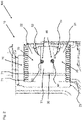
- FIG. 1 shows a boiler 100 for domestic hot water generation that includes a gas-fueled burner 30 arranged in a central part of a combustion chamber 20.
- a heat exchanger 70 is in thermal contact with the burner 30 and includes at least one duct for conducting a heat-absorbing fluid.
- the at least one duct winds in coils 71 around an outer periphery of the combustion chamber 20 so that the heat-absorbing fluid, in particular water, may absorb a substantial amount of heat generated in the combustion process.
- the burner 30 is of the surface-stabilized type and comprises a substantially cylindrical burner wall 31 that is perforated. Fuel gas supplied to the burner 30 by means of an intake 33 may traverse the burner wall 31 via holes. An injection electrode 52 for spark injection is adapted to ignite the fuel gas traversing the burner wall 31 to establish a stabilized flame strip on the outer surface of the cylindrical burner wall 30.
- the burner 100 is configured for premixed combustion.
- the intake 33 feeds a combustible mixture of gases comprising at least a fuel gas, in particular hydrogen, and air or oxygen to the burner.
- a detection electrode 51 for flame detection is configured to detect an ionization current that is established in particular when carbon-based fuel is combusted.
- the injection or spark electrode 52 and the detection electrode 51 are operatively connected to a controller, in particular micro-controller or printed circuit board, for controlled operation of the boiler 100, in particular in presence of a heat request or load.
- the cylindrical burner 30 is aligned in a horizontal direction with respect to the field of gravity in the combustion chamber 20.
- acid fluid or water is generated that eventually condenses and may be released from the combustion chamber 30 via a drain 23 and be further conducted to a condensate trap of the boiler 100.
- the drain 23 is located within the combustion chamber 20 at a low position with respect to the field of gravity such that the combustion chamber 20 may substantially be drained from condensate that accumulates within the combustion chamber 20 when the burner 30 is operated.
- the boiler 100 comprises a system 10 configured to detect such a backflow in a timely manner.
- the system 10 has a sensor for detecting fluid within the combustion chamber 20 that includes or is embodied by at least one probe 41 arranged in the lower part 21 of the combustion chamber 20.
- the probe 41 is configured to generate a well-defined and reproducible signal response when in direct physical contact with the fluid.
- the probe 41 is embodied by the detection electrode 51.
- the detection electrode 51 may transmit signals indicative of the ionization current to the controller, in particular in presence of a load or heat request. Water entry in the combustion chamber 20 may be detected by modified signals, in particular by an interruption of the ionization current or otherwise by a short circuit caused by fluid or water contacting the probe 41.
- the spark or injection electrode 52 may be arranged in the lower part 21 of the combustion chamber 20 to detect the water entry. In this case the detection typically relies by determining a short circuit when the injection electrode 52 is wetted or partially submerged in fluid.
- the controller shuts off and deactivates the boiler 100 in case fluid is detected by the at least one probe 41.
- the controller may direct the gas supply of the burner to be cut off in case of a clogged or blocked condensate trap.
- Fig. 2 shows a second embodiment of the system 10 for detection of the backflow of fluid that may in particular originate from a blocked condensate trap.
- the sensor 40 of the second embodiment comprises two probes or thermocouples 61, 62 that are arranged on the cylindrical burner wall 31 and project therefrom in opposite radial directions.
- the thermocouples 61, 62 are configured to measure temperatures by utilizing the Seebeck effect.
- the first thermocouple 61 is arranged in the lower part 21 of the combustion chamber 20, whereas the second thermocouple 62 is arranged in the upper part 22 of the combustion chamber.
- the first and second thermocouple are arranged relative to each other at an angle of about 180°.
- the first and the second thermocouple 61, 62 are arranged, in particular welded on the burner wall 31 to measure temperatures with respect to the surface temperature of the burner wall 31 as reference.
- the first thermocouple projects downwards from a lower portion of the burner surface 30 into the lower part 21 of the combustion chamber 20, whereas the second thermocouple 62 projects upwards from an upper portion of the burner surface 30 into the upper part 22 of the combustion chamber 20.
- the first thermocouple 61 generates signals that are proportional to the first temperature at in the lower part 21 of the combustion chamber 20.
- the second thermocouple 62 generates signals that are proportional to a second temperature at in the upper part 22 of the combustion chamber 20.
- the signals of the first and second thermocouples 61, 62 are received and evaluated by the controller of the boiler 100.
- the first and second temperatures are continuously or at least frequently detected and compared with each other, in particular by means of a plausibility algorithm for determining a water entry in the combustion chamber 20.
- the values detected by the thermocouples 61, 62 can be used to verify the correct operation of the boiler.
- Water entry in the combustion chamber 20 is detected by at least approximately determining or evaluating the difference of the first and the second temperatures that are respectively indicative of the temperature in the lower part 21 and in the upper part 22 of the combustion chamber 20.
- the controller immediately deactivates the boiler 100 in such an event.
- Fig. 3 shows a top view on a burner 30 arranged in the combustion chamber and two thermocouples 61, 62 arranged at different positions.
- the first and second thermocouple 61, 62 are arranged on the burner wall 31 in distance to each other in circumference direction of the burner wall 31.
- the first and second thermocouple are arranged in distance to each other by 45° in circumference direction of the burner wall 31.
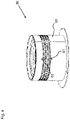
- Fig. 4 shows a perspective view on a burner 30 with two thermocouples 61, 62.
- the thermocouples are arranged in distance form each other along an axial direction of the burner 30.
- the two thermocouples 61, 62 are not arranged in distance form each other in circumference direction of the burner 30 so that the angle between the two thermocouples is 0°.
Landscapes
- Engineering & Computer Science (AREA)
- Physics & Mathematics (AREA)
- Thermal Sciences (AREA)
- Chemical & Material Sciences (AREA)
- Combustion & Propulsion (AREA)
- Mechanical Engineering (AREA)
- General Engineering & Computer Science (AREA)
- Regulation And Control Of Combustion (AREA)
Priority Applications (3)
| Application Number | Priority Date | Filing Date | Title |
|---|---|---|---|
| EP21187114.0A EP4123241A1 (fr) | 2021-07-22 | 2021-07-22 | Système et procédé de détection de reflux d'un fluide dans une chambre de combustion d'une chaudière |
| PCT/EP2022/070459 WO2023001949A1 (fr) | 2021-07-22 | 2022-07-21 | Chaudière et procédé de détection d'un reflux de fluide dans une chambre de combustion de la chaudière |
| EP22743513.8A EP4374116A1 (fr) | 2021-07-22 | 2022-07-21 | Chaudière et procédé de détection d'un reflux de fluide dans une chambre de combustion de la chaudière |
Applications Claiming Priority (1)
| Application Number | Priority Date | Filing Date | Title |
|---|---|---|---|
| EP21187114.0A EP4123241A1 (fr) | 2021-07-22 | 2021-07-22 | Système et procédé de détection de reflux d'un fluide dans une chambre de combustion d'une chaudière |
Publications (1)
| Publication Number | Publication Date |
|---|---|
| EP4123241A1 true EP4123241A1 (fr) | 2023-01-25 |
Family
ID=77316810
Family Applications (2)
| Application Number | Title | Priority Date | Filing Date |
|---|---|---|---|
| EP21187114.0A Withdrawn EP4123241A1 (fr) | 2021-07-22 | 2021-07-22 | Système et procédé de détection de reflux d'un fluide dans une chambre de combustion d'une chaudière |
| EP22743513.8A Pending EP4374116A1 (fr) | 2021-07-22 | 2022-07-21 | Chaudière et procédé de détection d'un reflux de fluide dans une chambre de combustion de la chaudière |
Family Applications After (1)
| Application Number | Title | Priority Date | Filing Date |
|---|---|---|---|
| EP22743513.8A Pending EP4374116A1 (fr) | 2021-07-22 | 2022-07-21 | Chaudière et procédé de détection d'un reflux de fluide dans une chambre de combustion de la chaudière |
Country Status (2)
| Country | Link |
|---|---|
| EP (2) | EP4123241A1 (fr) |
| WO (1) | WO2023001949A1 (fr) |
Cited By (1)
| Publication number | Priority date | Publication date | Assignee | Title |
|---|---|---|---|---|
| EP4464938A1 (fr) * | 2023-05-17 | 2024-11-20 | Vaillant GmbH | Procédé de détection d'un bourrage de condensat dans une chambre de combustion d'un appareil de chauffage, programme informatique, appareil de réglage et de commande et appareil de chauffage |
Citations (12)
| Publication number | Priority date | Publication date | Assignee | Title |
|---|---|---|---|---|
| GB2310942A (en) | 1996-03-04 | 1997-09-10 | James Andrew Forster | Burner with a carbon monoxide detection and automatic deactivation system |
| EP0619865B1 (fr) | 1991-04-19 | 1999-01-13 | BG plc | Capteur thermoelectrique |
| US20030049574A1 (en) | 2001-09-10 | 2003-03-13 | Bernard Dane | Gas appliance with a burner in the lower part, equipped with safety means, and resulting water heater |
| US20050079459A1 (en) | 2003-10-09 | 2005-04-14 | Claude Lesage | Flammable vapour detector system for hot water heater |
| GB2423141A (en) | 2005-02-14 | 2006-08-16 | Microgen Energy Ltd | Diagnostic circuit in a condensing boiler |
| EP1734316A2 (fr) * | 2005-06-18 | 2006-12-20 | Atmos Heating Systems | Chaudière à condensation |
| US20070281257A1 (en) | 2006-05-31 | 2007-12-06 | Aos Holding Company | Heating device having a secondary safety circuit for a fuel line and method of operating the same |
| GB2467752A (en) * | 2009-02-12 | 2010-08-18 | Raymund Lawton | Condensate line blockage warning sensor unit |
| EP2330346A2 (fr) | 2008-10-24 | 2011-06-08 | Worgas Bruciatori S.R.L. | Sonde de température pour brûleur et brûleur |
| WO2012123301A1 (fr) * | 2011-03-14 | 2012-09-20 | Giannoni France | Appareil de chauffage au gaz a condensation |
| US20180119989A1 (en) * | 2016-10-27 | 2018-05-03 | Noritz Corporation | Hot water apparatus |
| WO2020183289A1 (fr) | 2019-03-11 | 2020-09-17 | Polidoro S.P.A. | Capteur de température amélioré pour brûleur à gaz, et ensemble constitué desdits capteur et brûleur |
-
2021
- 2021-07-22 EP EP21187114.0A patent/EP4123241A1/fr not_active Withdrawn
-
2022
- 2022-07-21 EP EP22743513.8A patent/EP4374116A1/fr active Pending
- 2022-07-21 WO PCT/EP2022/070459 patent/WO2023001949A1/fr not_active Ceased
Patent Citations (12)
| Publication number | Priority date | Publication date | Assignee | Title |
|---|---|---|---|---|
| EP0619865B1 (fr) | 1991-04-19 | 1999-01-13 | BG plc | Capteur thermoelectrique |
| GB2310942A (en) | 1996-03-04 | 1997-09-10 | James Andrew Forster | Burner with a carbon monoxide detection and automatic deactivation system |
| US20030049574A1 (en) | 2001-09-10 | 2003-03-13 | Bernard Dane | Gas appliance with a burner in the lower part, equipped with safety means, and resulting water heater |
| US20050079459A1 (en) | 2003-10-09 | 2005-04-14 | Claude Lesage | Flammable vapour detector system for hot water heater |
| GB2423141A (en) | 2005-02-14 | 2006-08-16 | Microgen Energy Ltd | Diagnostic circuit in a condensing boiler |
| EP1734316A2 (fr) * | 2005-06-18 | 2006-12-20 | Atmos Heating Systems | Chaudière à condensation |
| US20070281257A1 (en) | 2006-05-31 | 2007-12-06 | Aos Holding Company | Heating device having a secondary safety circuit for a fuel line and method of operating the same |
| EP2330346A2 (fr) | 2008-10-24 | 2011-06-08 | Worgas Bruciatori S.R.L. | Sonde de température pour brûleur et brûleur |
| GB2467752A (en) * | 2009-02-12 | 2010-08-18 | Raymund Lawton | Condensate line blockage warning sensor unit |
| WO2012123301A1 (fr) * | 2011-03-14 | 2012-09-20 | Giannoni France | Appareil de chauffage au gaz a condensation |
| US20180119989A1 (en) * | 2016-10-27 | 2018-05-03 | Noritz Corporation | Hot water apparatus |
| WO2020183289A1 (fr) | 2019-03-11 | 2020-09-17 | Polidoro S.P.A. | Capteur de température amélioré pour brûleur à gaz, et ensemble constitué desdits capteur et brûleur |
Cited By (1)
| Publication number | Priority date | Publication date | Assignee | Title |
|---|---|---|---|---|
| EP4464938A1 (fr) * | 2023-05-17 | 2024-11-20 | Vaillant GmbH | Procédé de détection d'un bourrage de condensat dans une chambre de combustion d'un appareil de chauffage, programme informatique, appareil de réglage et de commande et appareil de chauffage |
Also Published As
| Publication number | Publication date |
|---|---|
| EP4374116A1 (fr) | 2024-05-29 |
| WO2023001949A1 (fr) | 2023-01-26 |
Similar Documents
| Publication | Publication Date | Title |
|---|---|---|
| CA2598803C (fr) | Element d'allumage de flamme a auto-diagnostic | |
| CA2367218C (fr) | Chauffe-eau au mazout avec detecteur de vapeurs inflammables et tube de debit induit connexe | |
| EP0619865B1 (fr) | Capteur thermoelectrique | |
| WO2023001949A1 (fr) | Chaudière et procédé de détection d'un reflux de fluide dans une chambre de combustion de la chaudière | |
| JP2019168209A (ja) | 燃焼監視装置及び燃焼制御システム | |
| CA3030273A1 (fr) | Assemblages pilotes et methodes destinees a des tours de torche elevees | |
| EP4352415A1 (fr) | Mécanisme de commande pour une chaudière à gaz | |
| US4995415A (en) | Partially flooded gas appliance safety shut-off method and apparatus | |
| US20070215066A1 (en) | Water heater with flammable vapor and co sensors | |
| CN113237095B (zh) | 一种点火装置、火焰检测方法、燃烧系统 | |
| US7051683B1 (en) | Gas heating device control | |
| US10260777B2 (en) | Gas fueled water heater appliance having a temperature control switch | |
| US20180363950A1 (en) | Thermistor system for temperature measurement in a gas water heater combustion chamber | |
| JP2012097932A (ja) | 給湯器 | |
| KR101938569B1 (ko) | 보일러의 배기연도 이탈검지 및 연소제어방법 | |
| US20180363949A1 (en) | Safety system for a gas fueled water heater | |
| US11821627B2 (en) | Method and heating unit for flame monitoring during gas combustion | |
| EP2447609B1 (fr) | Procédé de fonctionnement d'un brûleur de gaz atmosphérique assisté par ventilateur | |
| JP2019143904A (ja) | 火炎検出装置を持ったボイラ | |
| CZ2000966A3 (cs) | Způsob bezpečnostního řízení hořáku a zařízení k provádění tohoto způsobu | |
| KR0169054B1 (ko) | 응축수발생을 방지하는 가스보일러의 제어방법 | |
| WO2023203178A1 (fr) | Mécanisme de commande pour un appareil de combustion | |
| KR200222656Y1 (ko) | 발전용 보일러의 중유버너 누설유 경보장치 | |
| KR200182776Y1 (ko) | 보일러용 가스감지기의 경고기준 설정장치 | |
| EP1915573A1 (fr) | Procede et systeme de surveillance d'un bruleur |
Legal Events
| Date | Code | Title | Description |
|---|---|---|---|
| PUAI | Public reference made under article 153(3) epc to a published international application that has entered the european phase |
Free format text: ORIGINAL CODE: 0009012 |
|
| STAA | Information on the status of an ep patent application or granted ep patent |
Free format text: STATUS: THE APPLICATION HAS BEEN PUBLISHED |
|
| AK | Designated contracting states |
Kind code of ref document: A1 Designated state(s): AL AT BE BG CH CY CZ DE DK EE ES FI FR GB GR HR HU IE IS IT LI LT LU LV MC MK MT NL NO PL PT RO RS SE SI SK SM TR |
|
| STAA | Information on the status of an ep patent application or granted ep patent |
Free format text: STATUS: THE APPLICATION IS DEEMED TO BE WITHDRAWN |
|
| 18D | Application deemed to be withdrawn |
Effective date: 20230726 |