EP4124520B1 - Dispositif de connexion entre balai d' essuyage et bras d' entraînement - Google Patents
Dispositif de connexion entre balai d' essuyage et bras d' entraînement Download PDFInfo
- Publication number
- EP4124520B1 EP4124520B1 EP22187094.2A EP22187094A EP4124520B1 EP 4124520 B1 EP4124520 B1 EP 4124520B1 EP 22187094 A EP22187094 A EP 22187094A EP 4124520 B1 EP4124520 B1 EP 4124520B1
- Authority
- EP
- European Patent Office
- Prior art keywords
- adapter
- adapters
- connection device
- drive arm
- wiper blade
- Prior art date
- Legal status (The legal status is an assumption and is not a legal conclusion. Google has not performed a legal analysis and makes no representation as to the accuracy of the status listed.)
- Active
Links
Images
Classifications
-
- B—PERFORMING OPERATIONS; TRANSPORTING
- B60—VEHICLES IN GENERAL
- B60S—SERVICING, CLEANING, REPAIRING, SUPPORTING, LIFTING, OR MANOEUVRING OF VEHICLES, NOT OTHERWISE PROVIDED FOR
- B60S1/00—Cleaning of vehicles
- B60S1/02—Cleaning windscreens, windows or optical devices
- B60S1/04—Wipers or the like, e.g. scrapers
- B60S1/32—Wipers or the like, e.g. scrapers characterised by constructional features of wiper blade arms or blades
- B60S1/40—Connections between blades and arms
- B60S1/4003—Multi-purpose connections for two or more kinds of arm ends
-
- B—PERFORMING OPERATIONS; TRANSPORTING
- B60—VEHICLES IN GENERAL
- B60S—SERVICING, CLEANING, REPAIRING, SUPPORTING, LIFTING, OR MANOEUVRING OF VEHICLES, NOT OTHERWISE PROVIDED FOR
- B60S1/00—Cleaning of vehicles
- B60S1/02—Cleaning windscreens, windows or optical devices
- B60S1/04—Wipers or the like, e.g. scrapers
- B60S1/32—Wipers or the like, e.g. scrapers characterised by constructional features of wiper blade arms or blades
- B60S1/40—Connections between blades and arms
- B60S1/4038—Connections between blades and arms for arms provided with a channel-shaped end
- B60S1/4045—Connections between blades and arms for arms provided with a channel-shaped end comprising a detachable intermediate element mounted on the channel-shaped end
- B60S1/4048—Connections between blades and arms for arms provided with a channel-shaped end comprising a detachable intermediate element mounted on the channel-shaped end the element being provided with retention means co-operating with the channel-shaped end of the arm
- B60S2001/4051—Connections between blades and arms for arms provided with a channel-shaped end comprising a detachable intermediate element mounted on the channel-shaped end the element being provided with retention means co-operating with the channel-shaped end of the arm the intermediate element engaging the side walls of the arm
-
- B—PERFORMING OPERATIONS; TRANSPORTING
- B60—VEHICLES IN GENERAL
- B60S—SERVICING, CLEANING, REPAIRING, SUPPORTING, LIFTING, OR MANOEUVRING OF VEHICLES, NOT OTHERWISE PROVIDED FOR
- B60S1/00—Cleaning of vehicles
- B60S1/02—Cleaning windscreens, windows or optical devices
- B60S1/04—Wipers or the like, e.g. scrapers
- B60S1/32—Wipers or the like, e.g. scrapers characterised by constructional features of wiper blade arms or blades
- B60S1/40—Connections between blades and arms
- B60S1/4038—Connections between blades and arms for arms provided with a channel-shaped end
- B60S1/4045—Connections between blades and arms for arms provided with a channel-shaped end comprising a detachable intermediate element mounted on the channel-shaped end
- B60S1/4048—Connections between blades and arms for arms provided with a channel-shaped end comprising a detachable intermediate element mounted on the channel-shaped end the element being provided with retention means co-operating with the channel-shaped end of the arm
- B60S2001/4054—Connections between blades and arms for arms provided with a channel-shaped end comprising a detachable intermediate element mounted on the channel-shaped end the element being provided with retention means co-operating with the channel-shaped end of the arm the intermediate element engaging the back part of the arm
Definitions
- the present invention relates to the field of vehicle windshield wipers, and more particularly to connection devices for connecting a wiper blade to a drive arm.
- Vehicle wiper systems are designed to remove, by sweeping, liquids and dirt that could interfere with a driver's vision.
- These wiper systems generally include a drive arm, which performs an angular back-and-forth movement, and elongated wiper blades equipped with scraper blades made of a resilient material. The scraper blade rubs against the windshield and evacuates these liquids and dirt by sweeping them out of the driver's field of vision.
- the wiper blade is attached to the drive arm by a connection device that includes a connector and an adapter.
- the connector is a part that is secured to the wiper blade and is generally secured to the scraper blade.
- the adapter is a part that is interposed between the drive arm and the connector, being shaped to engage in an end part of the drive arm. The connector and adapter then cooperate to allow the articulated connection and the fixing of the wiper blade on the drive arm, thus forming the connection device of the wiper blade to the drive arm.
- the articulated connection between the connector and the adapter comprises at least one transverse pivot axis of the connector relative to the adapter, which is also a pivot axis of the wiper blade relative to the drive arm.
- One of the members for example the connector, generally comprises a substantially cylindrical shape which forms a pivot and which is received in a housing of complementary shape of the other member, here the adapter.
- An adapter is used to couple a wiper blade to a particular type of yoke or drive arm, and there are several varieties of end pieces. These varieties are similar in appearance but differ from each other in their dimensions, particularly in their widths or lateral dimensions. They also vary in the positions of the holes intended to cooperate with a locking push button on the adapter.
- a connection device can also comprise different adapters which can be associated by fitting into each other, the combination of these different adapters being capable of connecting to a particular type of drive arm to which each adapter taken separately cannot connect, thus multiplying the possibilities of assembling the same wiper blade.
- the association between a particular type of drive arm and a connection device can thus be based on the cooperation between the locking member arranged on the adapter and the orifice of the drive arm in which it is intended to be housed.
- the prior art nevertheless does not propose any other solution than to interchange the adapter according to the type of arm desired, which leads to a certain redundancy of the technical means which define these adapters.
- connection device allowing a superposition between the locking member of a first adapter and the locking member of a second adapter which fits onto this first adapter, the combination of these two adapters allowing them to cooperate with a type of drive arm different from the type of drive arm with which the first adapter taken in isolation can cooperate.
- An example of a connection device for a vehicle is described in the document DE102010030880 .
- An object of the present invention thus relates to a connection device for a vehicle, intended to connect a wiper blade to a drive arm, comprising at least one connector configured to be made integral with the wiper blade and at least two adapters, one of the adapters being configured to connect the connector to a first type of drive arm and a combination of the two adapters being configured to connect the connector to a second type of drive arm.
- each of these adapters comprises a locking member configured to lock the combination of the two adapters to the second type of drive arm, these locking members overlapping to secure the combination of the two adapters to the second type of drive arm and in that the locking members are retractable between a locking position intended to lock the adapters relative to the second type of drive arm and a mounting position intended to allow a translation of the adapters relative to the second type of drive arm.
- the connection device therefore comprises at least one connector and at least two adapters.
- This connector ensures the connection of the connection device to the wiper blade, while the adapters participate in connecting this connector to a particular type of drive arm.
- One of the adapters has a configuration such that it participates in connecting the connector to a first type of drive arm.
- another adapter such as proposed by the invention is added to it, the combination formed by these two adapters participates in connecting the connector to a second type of drive arm, distinct from the first type of drive arm.
- adapters are capable of cooperating with the drive arm adapted to receive this combination of adapters by means of their superimposed locking members, each adapter comprising such a locking member.
- the locking member of one of the adapters comes to overlap the locking member of the other adapter, securing the wiper blade to the drive arm.
- the blocking, or locking corresponds to an engagement of a portion of the locking members in an opening, for example an orifice or a hole, pierced in a wall of a yoke of the drive arm.
- these locking members prevent the translation of the connection device in a longitudinal direction, which corresponds to a direction of elongation of this connection device.
- the connection device must in fact be able, in order to be mounted in the drive arm, to slide therein.
- the locking members protrude from the connection device.
- protruding it is meant that the locking member of one of the adapters protrudes from the plane in which an upper wall of this adapter mainly extends, and that the locking member of the other adapter protrudes from the plane in which an upper wall of this other adapter mainly extends.
- protrusions constitute stop means, which prevent the translation of the connection device.
- the locking members no longer protrude and are thus retracted, and the sliding of the connection device in the yoke of the drive arm is then facilitated.
- each locking member comprises a flexible tab and a push button arranged at a free end of the flexible tab.
- tabs are flexible in the sense that they are elastically deformable in their range of elasticity, allowing in particular the locking members to retract and then return to a so-called locking position.
- the flexible tabs of the locking members are capable of overlapping, and are overlapped when the two adapters are nested.
- the push buttons of the locking members are capable of being superimposed, and are superimposed when the two adapters are nested. It is understood that the push button of one of the adapters can therefore cover, at least in part, in particular vertically, the push button of the other adapter.
- the locking members of the adapters When the locking members of the adapters are not superimposed, they are both in a rest position.
- rest position it is meant that the flexible tabs of these locking members are not elastically deformed, that is to say that they extend substantially in the planes or above the upper walls of the adapters that comprise them.
- the push button of the second adapter covers, at least in part, the push button of the first adapter. This push button of the second adapter then abuts against the push button of the first adapter and causes this flexible tab of the second adapter to come out of the plane in which the upper wall of the second adapter extends.
- the adapters comprise a first adapter and a second adapter, the push button of the first adapter being intended to be housed in an orifice of a yoke of the first type of drive arm, and the push buttons of the first adapter and the second adapter are intended to extend at least partly into a hole of a yoke of the second type of drive arm.
- the push button of the first adapter is configured to be housed in a hole made in the yoke of the first type of drive arm, thereby securing the first adapter to this first type of drive arm.
- the push buttons of each of the adapters are housed, at least in part, in a hole arranged in the yoke of the second type of drive arm. These two push buttons therefore participate in blocking the translation of the connection device.
- the two push buttons extend into the hole arranged in the yoke of the second type of drive arm such that the push button of the second adapter projects above the upper wall of the yoke of the second type of drive arm, while the push button of the first adapter extends at least into the thickness of this upper wall, for example by extending inside a cavity delimited by the push button of the second adapter.
- the push button of the first adapter is in contact with the push button of the second adapter when the locking members overlap.
- Such an overlay allows the combination of adapters to be secured to the second type of drive arm.
- the push button of the second adapter abuts against the push button of the first adapter. Such a stop elastically deforms the flexible tab on which the push button of the second adapter is arranged. Similarly, when the connection device is in the locking position in the drive arm, the stop of the push button of the second adapter against the push button of the first adapter elastically deforms the flexible tab of the first adapter. The push button of the first adapter is then at least partially retracted, i.e. it has not returned to its rest position.
- each adapter has a U-shaped section that delimits a housing, one of the adapters being arranged in the housing of the other adapter.
- the adapters which are therefore substantially U-shaped parts in cross section, can thus fit into each other.
- a U-shaped adapter can cover another U-shaped adapter, facilitating an association of several adapters within the same connection device.
- the adapters are associated with each other by removable interlocking.
- the adapters can thus be easily associated and dissociated, respectively by interlocking one in the housing of the other and by disengagement of one relative to the other.
- Such removable interlocking can in particular be a clipping.
- the invention further relates to a wiper blade comprising a connection device as described above.
- the invention further relates to a wiping system comprising a drive arm carrying a wiper blade comprising a connection device, the wiper blade being connected to the drive arm via the connection device described above.
- a longitudinal direction corresponds to a main direction of elongation of the wiper blade to which the connection device is made integral, this longitudinal direction being parallel to a longitudinal axis L of a reference L, V, T illustrated in the figures.
- a vertical direction corresponds to a direction in which the locking members are superimposed, this vertical direction being parallel to a vertical axis V of the reference L, V, T and this vertical axis V being perpendicular to the longitudinal axis L.
- a transverse direction corresponds to a direction parallel to a transverse axis T of the reference L, V, T, this transverse axis T being perpendicular to the longitudinal axis L and to the vertical axis V.
- the terms “lower” and “upper” relating to the elements of the connection device are understood to refer to the distance of these elements from the wiper blade, a lower end of such elements corresponding to the end arranged in the vicinity of this wiper blade while an upper end corresponds to the end arranged at a distance from the wiper blade.
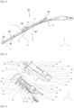
- FIG. 1 thus illustrates a wiping system 10 according to the invention, comprising a wiper blade 12 and a drive arm 59 for the wiper blade 12.
- the wiper blade 12 comprises a longitudinal body 16, a wiping blade 18, generally made of rubber, and at least one vertebra, not visible, which stiffens the wiping blade 18 and facilitates its application to a vehicle windshield.
- the wiper blade 12 schematically shown further comprises end pieces or clips 22 for attaching the wiper blade 18 and the vertebra to the longitudinal body 16, these end pieces 22 being located at each of the longitudinal ends of the longitudinal body 16.
- the wiper blade 12 carries, substantially in its middle, a connection device 1 according to the invention.
- This connection device 1 comprises in particular a connector 24, and at least two adapters.
- the adapters 25 and 29 participate in connecting the connector 24 to a particular type of drive arm, which is here a second type of drive arm 59.
- the adapters 25 and 29 are mounted on the connector 24 so as to maintain a degree of freedom in pivoting about a hinge axis Y which is a transverse axis substantially perpendicular to the longitudinal axis of the wiper blade 12. This degree of freedom allows the wiper blade 12 to pivot relative to the drive arm 59 and thus allows the wiper blade 12 to follow the curvature of the windshield during its movements.
- the adapters 25 and 29 can be detached from the drive arm 59, for example by pressing an actuation button, here a push button 891 carried by the second adapter 29.
- the drive arm 59 is driven by a motor, not shown, to follow an angular back-and-forth movement to evacuate water, and possibly other undesirable elements covering the windshield.
- the adapters 25 and 29 ensure the connection of the wiper blade 12 to the drive arm 59. More particularly, they participate in the connection of a head or yoke 28 of the drive arm 59, which can be formed in one piece with the drive arm 59 or even be added and fixed on a rod thereof.
- the yoke 28 has an elongated shape in a general direction substantially parallel to the longitudinal direction of the wiper blade 12.
- the yoke 28 is extended, at one of its longitudinal ends, by a connecting part 30 to the rod of the drive arm 59.
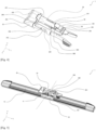
- FIG 2 shows a perspective view of the first adapter 25 and the second adapter 29 making up the connection device 1 of the figure 1 .
- the first adapter 25 extends mainly in the longitudinal direction, and has a substantially U-shaped cross section.
- This first adapter 25 can in particular, when it constitutes the only adapter of a connection device, participate in connecting the connector 24 to a first type of drive arm, not illustrated in the present figure. It may also, when used in combination with the second adapter 29, participate in connecting the connector 24 to a second type of drive arm, the drive arm 59 of the figure 1 .
- This first adapter 25 has a body 254 which comprises a first side wall 251 and a second side wall 252 substantially parallel to each other, at a distance from each other. These walls 251, 252 are connected to each other by an upper wall 250 which is substantially perpendicular to them.
- the walls 250, 251, 252 of this first adapter 25 have an elongated shape in the longitudinal direction, and they define between them an internal housing 253 intended to accommodate the connector 24.
- the side walls 251 and 252 are also equipped respectively with a first through-hole 451 and a second through-hole 452, open onto the internal housing 253.
- the first orifice 451 is substantially circular while the second orifice 452 is substantially parallelepipedal.
- These orifices 451 and 452 define a pivot axis of the first adapter 25 relative to the connector 24, not shown in the present figure, and by extension of the wiper blade 12 connected to the first adapter 25 relative to the drive arm connected to the connector 24.
- the body 254 of the first adapter 25 is connected to a head 255, the vertical and transverse dimensions of which are greater than those of the body 254 of the first adapter 25. It is thus understood that the head 255 extends beyond a longitudinal and transverse plane in which the upper wall 250 extends, and beyond a longitudinal and vertical plane in which the side walls 251 and 252 extend.
- the head 255 is in particular a locking means. Indeed, when the wiper blade 12 is assembled on the drive arm 59 by means of the connection device 1 as illustrated in the figure 1 , this head 255 forms a stop for the yoke 28 of the drive arm 59, thus preventing the translation of the latter beyond the body 254 of the first adapter 25.
- the upper wall 250 of the first adapter 25 narrows so as to form a point 257, which is in cantilevered relative to the body 255.
- the body 254 of the first adapter 25 and more particularly the side walls 251, 252 are each continued by an elastically deformable leg 256.
- These legs 256 can thus be brought closer to each other by elastic deformation.
- the legs 256 are substantially symmetrical along a plane of symmetry extending in longitudinal and vertical directions, located equidistant from the first side wall 251 and the second side wall 252.
- Each leg 256 further has a locking portion 456, shaped to cooperate with notches arranged on the yoke 28 of the drive arm 59 in order to lock the assembly of the first adapter 25 with the latter, thus constituting another locking means.
- the upper wall 250 is pierced with a first opening 259, a second opening 359 and a third opening 459, aligned in the longitudinal direction and opening onto the internal housing 253.
- the third opening 459 which is in the vicinity of the legs 256, is partly covered by a locking member 85.
- This locking member 85 comprises in particular a flexible tab 850 and a push button 851.
- This tab 850 extends mainly in the longitudinal direction and has a fixed end 853 at a distance from the legs 256, which is connected to the side wall 251 and to the side wall 252 by a bridge, and a free end 852, movable, in the vicinity of the legs 256.
- the tab 850 is elastically deformable and its free end 852 carries the push button 851.
- the tab 850 and the push button 851 can thus pivot about an axis A, located at the fixed end 853 which then plays a role of hinge for the locking member.
- the tab 850 is arranged in such a way that the push button 851 is located above a plane in which the upper wall 250 extends. This means that the push button 851 is at a distance from this upper wall 250 of the first adapter 25 in the vertical direction, opposite the internal housing 253.
- the push button 851 retracts to slide into this yoke and engages by elastic snap-fastening in a corresponding orifice of the yoke where it is housed in order to lock the first adapter 25 with respect to the latter.
- the second adapter 29 is a part whose cross section is substantially U-shaped.
- This second adapter 29 comprises an upper wall 290 as well as a first side wall 291 and a second side wall 292.
- the upper wall 290 extends mainly in a longitudinal direction and in a transverse direction, while the side walls 291 and 292 extend mainly in a longitudinal direction and a vertical direction.
- the side walls 291 and 292 are thus parallel to each other and perpendicular to the upper wall 290.
- These walls 290, 291 and 292 define an internal housing 293, this internal housing being in particular capable of receiving a connector 24 or another adapter.
- the second adapter 29 has a shoulder 301, which comprises a curved tab 296 extending from one of the longitudinal ends of the second adapter 29 and at a distance therefrom.
- This curved tab 296 participates in the assembly of the second adapter 29 with other parts and in particular with other adapters, such as for example the first adapter 25.
- This first adapter 25 in fact has, on one of the internal faces of its head 255 not visible on the figure 2 , an internal portion capable of receiving this curved tab 296 of the second adapter 29, thus forming a locking means.
- the upper wall 290 of the second adapter 29 is pierced with two parallel slots 294, arranged on the upper wall 290 in the vicinity of each of the side walls 291 and 292. These parallel slots 294 are aligned according to the transverse direction and open onto the internal housing 293. These parallel slots 294 open, at a longitudinal end of the second adapter 29 which does not carry the curved tab 296, onto an opening 297 also pierced in the upper wall 290.
- This opening 297 is partly covered by a locking member 89 constituting the second adapter 29.
- This locking member 89 comprises in particular a flexible tab 890 and a push button 891.
- This tab 890 is connected to the upper wall 290 of the second adapter 29 by a first end 893, and has a free end 892, at a distance from the longitudinal end which carries the curved tab 296 greater than the distance which separates this curved tab 296 from the first end 893.
- the tab 890 is elastically deformable, and its free end 892 carries the push button 891.
- the tab 890 and the push button 891 can thus pivot about an axis B, located at the first fixed end 893 which acts as a hinge. At rest, that is to say without constraint, the tab 890 is arranged in such a way that the push button 891 is located above the plane in which the upper wall 290 extends. It is understood that the push button 891 is at a distance from this upper wall 290 in the vertical direction, opposite the internal housing 293.
- FIG 3 is a perspective representation of a combination of the first adapter 25 and the second adapter 29 of the figure 2 .
- These two adapters 25 and 29 are here shown nested, as they are in the connection device 1 according to the invention.
- This is a removable nesting, that is to say that the adapters 25 and 29 can be alternately associated and dissociated, without destroying one or the other.
- This removable nesting can for example be a clipping.
- the first adapter 25 and the second adapter 29 both having U-shaped sections which delimit their respective internal housings 253 and 293, these adapters 25 and 29 can nest one inside the other.
- the first adapter 25 which is arranged in the internal housing 293 of the second adapter 29.
- the locking member 89 of the second adapter 29 is superimposed on the locking member 85 of the first adapter 25, thus making it possible to secure the combination of these adapters 25 and 29 to the second type of drive arm 59, shown in figure 5 .
- the tab 890 of the second adapter 29 covers the tab 850 of the first adapter 25.
- the push buttons 851 and 891 being able to overlap, the push button 891 of the second adapter 29 at least partially covers the push button 851 of the first adapter 25.
- connection device 1 is here secured to a wiper blade 12.
- the first adapter 25 comprises at least one pivot connection 31 mechanically connecting it to the connector 24, at its orifices 451 and 452.
- This pivot connection 31 constitutes an articulation which ensures the rotation of the connector 24 relative to the first adapter 25.
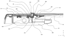
- FIG 5 is a sectional view of the combination of the first adapter 25 and the second adapter 29 of the figure 3 , this combination being here illustrated mounted in the second type of drive arm 59, and more particularly in the yoke 28 of this second type of drive arm 59.
- the locking member 85 of the first adapter 25 and the locking member 89 of the second adapter 29 are retractable between a position for locking the adapters 25 and 29 relative to the second drive arm 59 and a position for mounting these adapters 25 and 29 relative to this second drive arm 59.
- the mounting position corresponds to the position that the locking members 85 and 89 take when the adapters 25 and 29 are being inserted into the drive arm 59, and more precisely into the yoke 28 of this drive arm 59.
- the locking position corresponds to the position that the locking members 85 and 89 take once the adapters 25 and 29 are mounted in this yoke 28 of the drive arm 59, the translation of the adapters 25 and 29 in a longitudinal direction then being prevented by the locking members 85 and 89 combined with each other.
- the flexible tabs 850 and 890 of the locking members 85 and 89 are elastically deformed such that the tab 850 is no longer in the same plane as the upper wall 250 of the first adapter 25, and in the same way that the tab 890 is no longer in the same plane as the upper wall 290 of the second adapter 29.
- the push buttons 851 and 891 then retract into the internal housings 253 and 293 respectively, and therefore no longer protrude relative to these planes.
- the adapters 25 and 29 which they equip can then be inserted into the yoke 28 of the drive arm 59 without the translation necessary for such insertion being blocked by these projections.
- the push buttons 851 and 891 project relative to the planes in which the upper walls 250 and 290 of their respective adapters extend.
- the tab 890 of the second adapter 29 is aligned, in the longitudinal direction, with the upper wall 290 of the second adapter 29; both are in the same plane.
- the tab 850 of the first adapter 25 is not aligned with the upper wall 250 thereof in the longitudinal direction. This tab 850 of the first adapter 25 is in fact elastically deformed so that the push button 851 which it carries is, at least in part, retracted into the internal housing 253 of the first adapter 25.
- the push buttons 851 and 891 extend at least partly into a hole 595 of the yoke 28 of the second drive arm 59.
- These locking members 85 and 89 overlap in order to secure the combination of the adapters 25 and 29 to the drive arm 59, the push button 851 of the first adapter 25 being in contact with the push button 891 of the second adapter 29.
- This push button 85 of the first adapter 25 pushes the push button 89 of the second adapter 29 through the hole 595, towards the outside of a receiving cavity 280 of the yoke 28 in which the adapters 25 and 29 are located.
- the push button 891 of the second adapter 29 abuts against the thickness of the upper wall of the yoke 28.
- the push button 851 of the first adapter 25 extends into the thickness of this upper wall of the yoke 28.
- a nose 854 of the push button 851 of the first adapter 25 extends into a cavity 894 of the push button 891 of the second adapter 29.
- the push buttons 851 and 891 participate in blocking the translation in the longitudinal direction of the adapters 25 and 29 within the second drive arm 59.
- the present invention thus proposes a connection device in which the superposition of the locking members of a first adapter and a second adapter makes it possible to connect a wiper blade to a particular type of drive arm, such a drive arm being different from the type of drive arm with which the first adapter, alone, can cooperate.
Landscapes
- Engineering & Computer Science (AREA)
- Mechanical Engineering (AREA)
- Pivots And Pivotal Connections (AREA)
- Snaps, Bayonet Connections, Set Pins, And Snap Rings (AREA)
Description
- La présente invention concerne le domaine des essuie-glaces pour véhicule, et plus particulièrement les dispositifs de connexion permettant de connecter un balai d'essuyage à un bras d'entraînement.
- Les systèmes d'essuyage pour véhicule sont conçus pour retirer, par balayage, les liquides et salissures qui pourraient perturber la vision d'un conducteur. Ces systèmes d'essuyage comprennent en général un bras d'entraînement, qui effectue un mouvement de va-et-vient angulaire, et des balais d'essuyage allongés équipés de lames racleuses réalisées en une matière élastique. La lame racleuse frotte contre le pare-brise et évacue ces liquides et salissures en les balayant en dehors du champ de vision du conducteur.
- Le balai d'essuyage est rattaché au bras d'entraînement par un dispositif de connexion qui comprend un connecteur et un adaptateur. Le connecteur est une pièce qui est solidarisée au balai d'essuyage et qui est en général solidaire de la lame racleuse. L'adaptateur est une pièce qui est interposée entre le bras d'entraînement et le connecteur, en étant conformé pour s'engager dans une pièce terminale du bras d'entraînement. Connecteur et adaptateur coopèrent ensuite pour permettre la liaison articulée et la fixation du balai d'essuyage sur le bras d'entraînement, formant ainsi le dispositif de connexion du balai d'essuyage au bras d'entraînement.
- La liaison articulée entre le connecteur et l'adaptateur comprend au moins un axe transversal de pivotement du connecteur vis-à-vis de l'adaptateur, qui est également un axe de pivotement du balai d'essuyage vis-à-vis du bras d'entraînement. L'un des organes, par exemple le connecteur, comprend en général une forme sensiblement cylindrique qui forme un pivot et qui est reçue dans un logement de forme complémentaire de l'autre organe, ici l'adaptateur.
- Un adaptateur permet d'associer un balai d'essuyage à un type particulier de chape ou de bras d'entraînement, et il existe plusieurs variétés de pièces terminales. Ces variétés sont proches en apparence mais diffèrent les unes des autres par leurs dimensions, en particulier par leurs largeurs ou dimensions latérales. Elles varient également par les positions des orifices destinés à coopérer avec un bouton poussoir de verrouillage de l'adaptateur.
- Il existe ainsi différents adaptateurs, de façon à pouvoir associer un balai d'essuyage donné à plusieurs pièces terminales et par extension à plusieurs bras d'entraînement. Un dispositif de connexion peut par ailleurs comprendre différents adaptateurs pouvant s'associer par emboîtement les uns dans les autres, la combinaison de ces différents adaptateurs étant capable de se connecter à un type particulier de bras d'entraînement auquel chaque adaptateur pris séparément ne peut pas se connecter, multipliant ainsi les possibilités d'assemblage d'un même balai d'essuyage.
- L'association entre un type particulier de bras d'entraînement et un dispositif de connexion peut ainsi reposer sur la coopération entre l'organe de verrouillage disposé sur l'adaptateur et l'orifice du bras d'entraînement dans lequel il est destiné à se loger. Il existe plusieurs types de bras d'entraînement avec un orifice ménagé sur la paroi supérieure du bras, qui diffèrent les uns des autres au moins par la position de cet orifice. L'art antérieur ne propose néanmoins pas d'autre solution que d'interchanger l'adaptateur en fonction du type de bras souhaité, ce qui conduit à une certaine redondance des moyens techniques qui définissent ces adaptateurs.
- La présente invention s'inscrit dans ce contexte en proposant un dispositif de connexion permettant une superposition entre l'organe de verrouillage d'un premier adaptateur et l'organe de verrouillage d'un deuxième adaptateur qui s'emboîte sur ce premier adaptateur, la combinaison de ces deux adaptateurs leur permettant de coopérer avec un type de bras d'entraînement différent du type de bras d'entraînement avec lequel le premier adaptateur pris isolément peut coopérer. Un exemple de dispositif de connexion pour véhicule est décrit dans le document
DE102010030880 . - Un objet de la présente invention concerne ainsi un dispositif de connexion pour véhicule, destiné à relier un balai d'essuyage à un bras d'entraînement, comprenant au moins un connecteur configuré pour être rendu solidaire du balai d'essuyage et au moins deux adaptateurs, l'un des adaptateurs étant configuré pour relier le connecteur à un premier type de bras d'entraînement et une combinaison des deux adaptateurs étant configurée pour relier le connecteur à un deuxième type de bras d'entraînement. Selon l'invention, chacun de ces adaptateurs comprend un organe de verrouillage configuré pour verrouiller la combinaison des deux adaptateurs au deuxième type de bras d'entraînement, ces organes de verrouillage se superposant pour solidariser la combinaison des deux adaptateurs au deuxième type de bras d'entraînement et en ce que les organes de verrouillage sont escamotables entre une position de blocage destinée à bloquer les adaptateurs par rapport au deuxième type de bras d'entraînement et une position de montage destinée à autoriser une translation des adaptateurs par rapport au deuxième type de bras d'entraînement.
- Le dispositif de connexion comprend donc au moins un connecteur et au moins deux adaptateurs. Ce connecteur assure la liaison du dispositif de connexion au balai d'essuyage, tandis que les adaptateurs participent à relier ce connecteur à un type particulier de bras d'entraînement. L'un des adaptateurs présente une configuration telle qu'il participe à relier le connecteur à un premier type de bras d'entraînement. Toutefois, lorsqu'on lui adjoint un autre adaptateur tel que proposé par l'invention, la combinaison formée par ces deux adaptateurs participe à relier le connecteur à un deuxième type de bras d'entraînement, distinct du premier type de bras d'entraînement.
- Ces adaptateurs sont aptes à coopérer avec le bras d'entraînement adapté à la réception de cette combinaison d'adaptateurs par le biais de leurs organes de verrouillage superposés, chaque adaptateur comprenant un tel organe de verrouillage. Lors de l'assemblage des adaptateurs pour former la combinaison capable de participer à relier le connecteur au deuxième type de bras d'entraînement, l'organe de verrouillage de l'un des adaptateurs vient se superposer à l'organe de verrouillage de l'autre adaptateur, solidarisant le balai d'essuyage au bras d'entraînement.
- Le blocage, ou verrouillage, correspond à un enclenchement d'une portion des organes de verrouillage dans une ouverture, par exemple un orifice ou un trou, percée dans une paroi d'une chape du bras d'entraînement. Lorsque les organes de verrouillage sont dans une position de blocage de l'adaptateur, ces organes de verrouillage empêchent la translation du dispositif de connexion selon une direction longitudinale, qui correspond à une direction d'allongement de ce dispositif de connexion. A l'inverse, lorsque les organes de verrouillage sont dans une position de montage de l'adaptateur, une telle translation est facilitée. Le dispositif de connexion doit en effet pouvoir, afin d'être monté dans le bras d'entraînement, coulisser dans celui-ci.
- Dans la position de blocage, les organes de verrouillage font saillie du dispositif de connexion. On entend par faire saillie que l'organe de verrouillage de l'un des adaptateurs dépasse du plan dans lequel s'étend principalement une paroi supérieure de cet adaptateur, et que l'organe de verrouillage de l'autre adaptateur dépasse du plan dans lequel s'étend principalement une paroi supérieure de cet autre adaptateur. De telles saillies constituent des moyens de butée, qui empêchent la translation du dispositif de connexion. Au contraire, dans la position de montage les organes de verrouillage ne font plus saillie et sont ainsi escamotés, et le coulissement du dispositif de connexion dans la chape du bras d'entraînement est alors facilité.
- Selon une autre caractéristique de l'invention, chaque organe de verrouillage comprend une languette souple et un bouton poussoir disposé à une extrémité libre de la languette souple.
- Ces languettes sont souples en ce sens qu'elles sont déformables élastiquement dans leur domaine d'élasticité, permettant notamment aux organes de verrouillage de s'escamoter puis de revenir à une position dite de blocage.
- Selon une autre caractéristique, les languettes souples des organes de verrouillage sont aptes à se superposer, et sont superposées lorsque les deux adaptateurs sont imbriqués.
- Selon une caractéristique, les boutons poussoirs des organes de verrouillage sont aptes à se superposer, et sont superposés lorsque les deux adaptateurs sont imbriqués. On comprend que le bouton poussoir de l'un des adaptateurs peut donc recouvrir, au moins en partie, notamment verticalement, le bouton poussoir de l'autre adaptateur.
- Lorsque les organes de verrouillage des adaptateurs ne sont pas superposés, ils sont tous deux dans une position de repos. On entend par position de repos que les languettes souples de ces organes de verrouillage ne sont pas déformées élastiquement, c'est-à-dire qu'elles s'étendent sensiblement dans les plans ou au-dessus des parois supérieures des adaptateurs qui les comprenne. À l'inverse, lorsque les organes de verrouillage sont superposés, le bouton poussoir du deuxième adaptateur recouvre, au moins en partie, le bouton poussoir du premier adaptateur. Ce bouton poussoir du deuxième adaptateur vient alors en butée contre le bouton poussoir du premier adaptateur et conduit cette languette souple du deuxième adaptateur à sortir du plan dans lequel s'étend la paroi supérieure du deuxième adaptateur.
- Selon une autre caractéristique, les adaptateurs comprennent un premier adaptateur et un deuxième adaptateur, le bouton poussoir du premier adaptateur étant destiné à se loger dans un orifice d'une chape du premier type de bras d'entraînement, et les boutons poussoirs du premier adaptateur et du deuxième adaptateur sont destinés à s'étendre au moins en partie dans un trou d'une chape du second type de bras d'entraînement.
- Le bouton poussoir du premier adaptateur est configuré pour se loger dans un orifice réalisé dans la chape du premier type de bras d'entraînement, solidarisant ainsi le premier adaptateur à ce premier type de bras d'entraînement. En présence d'une combinaison de deux adaptateurs, comme c'est le cas dans le présent dispositif de connexion, les boutons poussoirs de l'un et l'autre des adaptateurs se logent, au moins en partie, dans un trou ménagé dans la chape du second type de bras d'entraînement. Ces deux boutons poussoirs participent donc à bloquer la translation du dispositif de connexion. Les deux boutons poussoirs s'étendent dans le trou ménagé dans la chape du second type de bras d'entraînement de telle sorte que le bouton poussoir du deuxième adaptateur fait saillie au-dessus de la paroi supérieure de la chape du second type de bras d'entraînement, tandis que le bouton poussoir du premier adaptateur s'étend au moins dans l'épaisseur de cette paroi supérieure, par exemple en s'étendant à l'intérieur d'une cavité délimitée par le bouton poussoir du deuxième adaptateur.
- Selon une caractéristique de l'invention, le bouton poussoir du premier adaptateur est au contact du bouton poussoir du deuxième adaptateur quand les organes de verrouillage se superposent.
- Une telle superposition permet de solidariser la combinaison des adaptateurs au deuxième type de bras d'entraînement.
- Le bouton poussoir du deuxième adaptateur vient en butée contre le bouton poussoir du premier adaptateur. Une telle butée déforme élastiquement la languette souple sur laquelle est disposé le bouton poussoir du deuxième adaptateur. De la même façon, lorsque le dispositif de connexion est en position de blocage dans le bras d'entraînement, la butée du bouton poussoir du deuxième adaptateur contre le bouton poussoir du premier adaptateur déforme élastiquement la languette souple du premier adaptateur. Le bouton poussoir du premier adaptateur est alors au moins en partie escamoté, c'est-à-dire qu'il n'est pas revenu dans sa position de repos.
- Selon une autre caractéristique, chaque adaptateur présente une section en U qui délimite un logement, l'un des adaptateurs étant disposé dans le logement de l'autre adaptateur. Les adaptateurs, qui sont donc des pièces sensiblement en forme de U selon une section transversale, peuvent ainsi s'imbriquer les uns dans les autres. Un adaptateur en U peut recouvrir un autre adaptateur en U, facilitant une association de plusieurs adaptateurs au sein d'un même dispositif de connexion.
- Selon une caractéristique de l'invention, les adaptateurs sont associés l'un à l'autre par emboîtement amovible. Les adaptateurs peuvent ainsi être associés et dissociés aisément, respectivement par emboîtement de l'un dans le logement de l'autre et par déboîtement de l'un par rapport à l'autre. Un tel emboîtement amovible peut notamment être un clipsage.
- L'invention concerne en outre un balai d'essuyage comprenant un dispositif de connexion tel que décrit précédemment.
- L'invention porte par ailleurs sur un système d'essuyage comprenant un bras d'entraînement porteur d'un balai d'essuyage comprenant un dispositif de connexion, le balai d'essuyage étant relié au bras d'entraînement par l'intermédiaire du dispositif de connexion décrit ci-dessus.
- D'autres caractéristiques, détails et avantages de l'invention ressortiront plus clairement à la lecture de la description qui suit d'une part, et d'un exemple de réalisation donné à titre indicatif et non limitatif en référence aux dessins annexés d'autre part, sur lesquels :
- [
Fig. 1 ] présente, schématiquement, une vue en perspective d'un système d'essuyage dans lequel un dispositif de connexion selon l'invention relie un balai d'essuyage à un bras d'entraînement ; - [
Fig. 2 ] est une vue en perspective d'un premier adaptateur et d'un deuxième adaptateur composant le dispositif de connexion de lafigure 1 ; - [
Fig. 3 ] est une vue en perspective d'une combinaison du premier adaptateur et du deuxième adaptateur de lafigure 2 , le premier adaptateur étant emboîté dans le deuxième adaptateur ; - [
Fig. 4 ] est une vue en perspective du dispositif de connexion de lafigure 1 , solidaire d'un balai d'essuyage ; - [
Fig. 5 ] est une vue de coupe de la combinaison du premier adaptateur et du deuxième adaptateur de lafigure 3 , montée dans un deuxième type de bras d'entraînement. - Sur les figures, les éléments communs à plusieurs figures conservent la même référence.
- Dans la description détaillée qui va suivre, les dénominations « longitudinale », « transversale » et « verticale » se réfèrent à l'orientation du dispositif de connexion selon l'invention. Une direction longitudinale correspond à une direction principale d'allongement du balai d'essuyage duquel le dispositif de connexion est rendu solidaire, cette direction longitudinale étant parallèle à un axe longitudinal L d'un repère L, V, T illustré sur les figures. Une direction verticale correspond à une direction dans laquelle se superposent les organes de verrouillage, cette direction verticale étant parallèle à un axe vertical V du repère L, V, T et cet axe vertical V étant perpendiculaire à l'axe longitudinal L. Enfin, une direction transversale correspond à une direction parallèle à un axe transversal T du repère L, V, T, cet axe transversal Tétant perpendiculaire à l'axe longitudinal L et à l'axe vertical V.
- En outre, les dénominations « inférieure » et « supérieure » concernant les éléments du dispositif de connexion s'entendent relativement à l'éloignement de ces éléments du balai d'essuyage, une extrémité inférieure de tels éléments correspondant à l'extrémité disposée au voisinage de ce balai d'essuyage tandis qu'une extrémité supérieure correspond à l'extrémité disposée à distance du balai d'essuyage.
- La
figure 1 illustre ainsi un système d'essuyage 10 selon l'invention, comportant un balai d'essuyage 12 et un bras d'entraînement 59 du balai d'essuyage 12. Le balai d'essuyage 12 comprend un corps longitudinal 16, une lame d'essuyage 18, en général en caoutchouc, et au moins une vertèbre, non visible, qui rigidifie la lame d'essuyage 18 et favorise son application sur un pare-brise de véhicule. - Le balai d'essuyage 12 schématiquement représenté comprend en outre des embouts d'extrémité ou agrafes d'accrochage 22 de la lame d'essuyage 18 et de la vertèbre sur le corps longitudinal 16, ces embouts d'extrémité 22 étant situés à chacune des extrémités longitudinales du corps longitudinal 16.
- Le balai d'essuyage 12 porte, sensiblement en son milieu, un dispositif de connexion 1 selon l'invention. Ce dispositif de connexion 1 comprend notamment un connecteur 24, et au moins deux adaptateurs.
- Ces au moins deux adaptateurs, ici un premier adaptateur 25 et un deuxième adaptateur 29, participent à relier le connecteur 24 à un type particulier de bras d'entraînement, qui est ici un deuxième type de bras d'entraînement 59. Les adaptateurs 25 et 29 sont montés sur le connecteur 24 de façon à garder un degré de liberté en pivotement autour d'un axe d'articulation Y qui est un axe transversal sensiblement perpendiculaire à l'axe longitudinal du balai d'essuyage 12. Ce degré de liberté autorise un pivotement du balai d'essuyage 12 vis-à-vis du bras d'entraînement 59 et permet ainsi au balai d'essuyage 12 de suivre la courbure du pare-brise lors de ses déplacements. Les adaptateurs 25 et 29 peuvent être désolidarisés du bras d'entraînement 59, par exemple par appui sur un bouton d'actionnement, ici un bouton poussoir 891 porté par le deuxième adaptateur 29.
- Le bras d'entraînement 59 est entraîné par un moteur, non représenté, pour suivre un mouvement angulaire de va-et-vient permettant d'évacuer l'eau, et éventuellement d'autres éléments indésirables recouvrant le pare-brise. Les adaptateurs 25 et 29 assurent la liaison du balai d'essuyage 12 au bras d'entraînement 59. Plus particulièrement, ils participent à la liaison d'une tête ou chape 28 du bras d'entraînement 59, qui peut être formée d'un seul tenant avec le bras d'entraînement 59 ou encore être rapportée et fixée sur une tige de celui-ci.
- La chape 28 a une forme allongée selon une direction générale sensiblement parallèle à la direction longitudinale du balai d'essuyage 12. La chape 28 se prolonge, à l'une de ses extrémités longitudinales, par une partie de liaison 30 à la tige du bras d'entraînement 59.
- La
figure 2 présente une vue en perspective du premier adaptateur 25 et du deuxième adaptateur 29 composant le dispositif de connexion 1 de lafigure 1 . - Le premier adaptateur 25 s'étend principalement selon la direction longitudinale, et présente une section transversale sensiblement en forme de U. Ce premier adaptateur 25 peut notamment, lorsqu'il constitue l'unique adaptateur d'un dispositif de connexion, participer à relier le connecteur 24 à un premier type de bras d'entraînement, non illustré sur la présente figure. Il peut également, lorsqu'il est utilisé en combinaison avec le deuxième adaptateur 29, participer à relier le connecteur 24 à un deuxième type de bras d'entraînement, le bras d'entraînement 59 de la
figure 1 . - Ce premier adaptateur 25 présente un corps 254 qui comprend une première paroi latérale 251 et une deuxième paroi latérale 252 sensiblement parallèles entre elles, à distance l'une de l'autre. Ces parois 251, 252 sont reliées entre elles par une paroi supérieure 250 qui leur est sensiblement perpendiculaire. Les parois 250, 251, 252 de ce premier adaptateur 25 présentent une forme allongée selon la direction longitudinale, et elles définissent entre elles un logement interne 253 destiné à accueillir le connecteur 24.
- Les parois latérales 251 et 252 sont par ailleurs équipées respectivement d'un premier orifice traversant 451 et d'un deuxième orifice traversant 452, ouverts sur le logement interne 253. Le premier orifice 451 est sensiblement circulaire tandis que le deuxième orifice 452 est sensiblement parallélépipédique. Ces orifices 451 et 452 définissent un axe de pivotement du premier adaptateur 25 relativement au connecteur 24, non représenté sur la présente figure, et par extension du balai d'essuyage 12 relié au premier adaptateur 25 relativement au bras d'entraînement relié au connecteur 24.
- À une de ses extrémités longitudinales, le corps 254 du premier adaptateur 25 est relié à une tête 255, dont les dimensions verticales et transversales sont supérieures à celles du corps 254 du premier adaptateur 25. On comprend ainsi que la tête 255 s'étend au-delà d'un plan longitudinal et transversal dans lequel s'étend la paroi supérieure 250, et au-delà d'un plan longitudinal et vertical dans lequel s'étendent les parois latérales 251 et 252. La tête 255 est notamment un moyen de verrouillage. En effet, lorsque le balai d'essuyage 12 est assemblé sur le bras d'entraînement 59 par l'intermédiaire du dispositif de connexion 1 comme illustré sur la
figure 1 , cette tête 255 forme une butée pour la chape 28 du bras d'entraînement 59, empêchant ainsi la translation de celle-ci au-delà du corps 254 du premier adaptateur 25. - À une autre de ses extrémités longitudinales, la paroi supérieure 250 du premier adaptateur 25 se rétrécit de façon à former une pointe 257, qui est en porte-à-faux par rapport au corps 255. Au niveau de cette autre extrémité longitudinale, le corps 254 du premier adaptateur 25 et plus particulièrement les parois latérales 251, 252 se poursuivent chacune par une jambe 256 déformable élastiquement. Ces jambes 256 peuvent ainsi être rapprochées l'une de l'autre par déformation élastique. Les jambes 256 sont sensiblement symétriques selon un plan de symétrie s'étendant dans des directions longitudinale et verticale, situé à équidistance de la première paroi latérale 251 et de la deuxième paroi latérale 252. Chaque jambe 256 présente en outre une portion de verrouillage 456, conformée pour coopérer avec des encoches disposées sur la chape 28 de bras d'entraînement 59 afin de verrouiller l'assemblage du premier adaptateur 25 avec cette dernière, constituant ainsi un autre moyen de verrouillage.
- La paroi supérieure 250 est percée d'une première ouverture 259, une deuxième ouverture 359 et une troisième ouverture 459, alignées selon la direction longitudinale et donnant sur le logement interne 253. La troisième ouverture 459, qui est au voisinage des jambes 256, est en partie recouverte par un organe de verrouillage 85. Cet organe de verrouillage 85 comprend notamment une languette souple 850 et un bouton poussoir 851. Cette languette 850 s'étend principalement selon la direction longitudinale et présente une extrémité fixe 853 à distance des jambes 256, qui est reliée à la paroi latérale 251 et à la paroi latérale 252 par un pontet, et une extrémité libre 852, mobile, au voisinage des jambes 256. La languette 850 est déformable élastiquement et son extrémité libre 852 porte le bouton poussoir 851. La languette 850 et le bouton poussoir 851 peuvent ainsi pivoter autour d'un axe A, situé au niveau de l'extrémité fixe 853 qui joue alors un rôle de charnière pour l'organe de verrouillage. Au repos, c'est-à-dire sans contrainte, la languette 850 est disposée d'une façon telle que le bouton poussoir 851 se situe au-dessus d'un plan dans lequel s'étend la paroi supérieure 250. On entend par là que le bouton poussoir 851 est à distance de cette paroi supérieure 250 du premier adaptateur 25 selon la direction verticale, à l'opposé du logement interne 253. Lors du montage par translation du premier adaptateur 25 dans une chape d'un premier type de bras d'entraînement, le bouton poussoir 851 s'escamote pour glisser dans cette chape et s'engage par encliquetage élastique dans un orifice correspondant de la chape où il se loge afin de verrouiller le premier adaptateur 25 vis-à-vis de cette dernière.
- Le deuxième adaptateur 29 est une pièce dont une section transversale est sensiblement en forme de U. Ce deuxième adaptateur 29 comporte une paroi supérieure 290 ainsi qu'une première paroi latérale 291 et une deuxième paroi latérale 292. La paroi supérieure 290 s'étend principalement selon une direction longitudinale et selon une direction transversale, tandis que les parois latérales 291 et 292 s'étendent principalement selon une direction longitudinale et une direction verticale. Les parois latérales 291 et 292 sont ainsi parallèles entre elles et perpendiculaires à la paroi supérieure 290. Ces parois 290, 291 et 292 définissent un logement interne 293, ce logement interne étant notamment apte à recevoir un connecteur 24 ou un autre adaptateur. Le deuxième adaptateur 29 présente un épaulement 301, qui comporte une patte courbée 296 s'étendant depuis une des extrémités longitudinales du deuxième adaptateur 29 et à distance de celle-ci. Cette patte courbée 296 participe à l'assemblage du deuxième adaptateur 29 avec d'autres pièces et notamment avec d'autres adaptateurs, comme par exemple le premier adaptateur 25. Ce premier adaptateur 25 présente en effet, sur l'une des faces internes de sa tête 255 non visible sur la
figure 2 , une portion interne apte à recevoir cette patte courbée 296 du deuxième adaptateur 29, formant ainsi un moyen de verrouillage. - L'épaulement 301 de l'extrémité longitudinale du deuxième adaptateur 29 qui comporte la patte courbée 296 se prolonge, à distance de cette patte courbée 296, par deux oreilles 302 qui sont plaqués contre les parois latérales 291 et 292. Ces oreilles 302 permettent d'arrimer le deuxième adaptateur 29 à un bras d'entraînement, et constituent à ce titre d'autres moyens de verrouillage.
- La paroi supérieure 290 du deuxième adaptateur 29 est percée de deux fentes parallèles 294, disposées sur la paroi supérieure 290 au voisinage de chacune des parois latérales 291 et 292. Ces fentes parallèles 294 sont alignées selon la direction transversale et donnent sur le logement interne 293. Ces fentes parallèles 294 débouchent, à une extrémité longitudinale du deuxième adaptateur 29 qui ne porte pas la patte courbée 296, sur une ouverture 297 percée elle aussi dans la paroi supérieure 290. Cette ouverture 297 est en partie recouverte par un organe de verrouillage 89 constitutif du deuxième adaptateur 29. Cet organe de verrouillage 89 comprend notamment une languette souple 890 et un bouton poussoir 891. Cette languette 890 est reliée à la paroi supérieure 290 du deuxième adaptateur 29 par une première extrémité 893, et présente une extrémité libre 892, à une distance de l'extrémité longitudinale qui porte la patte courbée 296 plus importante que la distance qui sépare cette patte courbée 296 de la première extrémité 893. La languette 890 est déformable élastiquement, et son extrémité libre 892 porte le bouton poussoir 891. La languette 890 et le bouton poussoir 891 peuvent ainsi pivoter autour d'un axe B, situé au niveau de la première extrémité fixe 893 qui joue le rôle de charnière. Au repos, c'est-à-dire sans contrainte, la languette 890 est disposée d'une façon telle que le bouton poussoir 891 se situe au-dessus du plan dans lequel s'étend la paroi supérieure 290. On comprend que le bouton poussoir 891 est à distance de cette paroi supérieure 290 selon la direction verticale, à l'opposé du logement interne 293.
- La
figure 3 est une représentation en perspective d'une combinaison du premier adaptateur 25 et du deuxième adaptateur 29 de lafigure 2 . Ces deux adaptateurs 25 et 29 sont ici représentés emboîtés, tels qu'ils le sont dans le dispositif de connexion 1 selon l'invention. Il s'agit d'un emboîtement amovible, c'est-à-dire que les adaptateurs 25 et 29 peuvent être tour à tour associés et dissociés, sans destruction de l'un ou de l'autre. Cet emboîtement amovible peut par exemple être un clipsage. Le premier adaptateur 25 et le deuxième adaptateur 29 présentant tous deux des sections en U qui délimitent leurs logements internes 253 et 293 respectifs, ces adaptateurs 25 et 29 peuvent s'emboîter l'un dans l'autre. C'est ici le premier adaptateur 25 qui est disposé dans le logement interne 293 du deuxième adaptateur 29. - Lorsque le premier adaptateur 25 et le deuxième adaptateur 29 sont ainsi combinés, le deuxième adaptateur 29 recouvre le premier adaptateur 25 de telle sorte que ses parois latérales 291, 292 sont placées en regard des parois latérales 251, 252 du premier adaptateur 25. La paroi supérieure 290 du deuxième adaptateur 29 recouvre partiellement la paroi supérieure 250 du premier adaptateur 25, ce deuxième adaptateur 29 reposant sur le corps 254 du premier adaptateur 25.
- L'organe de verrouillage 89 du deuxième adaptateur 29 se superpose à l'organe de verrouillage 85 du premier adaptateur 25, permettant ainsi de solidariser la combinaison de ces adaptateurs 25 et 29 au deuxième type de bras d'entraînement 59, représenté en
figure 5 . La languette 890 du deuxième adaptateur 29 vient recouvrir la languette 850 du premier adaptateur 25. De la même façon, les boutons poussoirs 851 et 891 étant aptes à se superposer, le bouton poussoir 891 du deuxième adaptateur 29 recouvre au moins en partie le bouton poussoir 851 du premier adaptateur 25. - Sur la
figure 4 , la combinaison entre le premier adaptateur 25 et le deuxième adaptateur 29 telle que décrite précédemment est associée à un connecteur 24 pour former un dispositif de connexion 1 selon l'invention. Ce dispositif de connexion 1 est ici solidarisé à un balai d'essuyage 12. Le premier adaptateur 25 comprend au moins une liaison pivot 31 le reliant mécaniquement au connecteur 24, au niveau de ses orifices 451 et 452. Cette liaison pivot 31 constitue une articulation qui assure la rotation du connecteur 24 par rapport au premier adaptateur 25. Ainsi, lorsque le connecteur 24 est solidaire d'un balai d'essuyage 12 comme c'est le cas sur la présente figure, par exemple par sertissage, ce balai d'essuyage 12 peut pivoter par rapport au premier adaptateur 25 et au bras d'entraînement 59 auquel ce premier adaptateur 25 est relié. De ce fait, le balai d'essuyage 12 peut lors de ses déplacements suivre parfaitement la surface courbée du pare-brise du véhicule qu'il équipe. - La
figure 5 est une vue de coupe de la combinaison du premier adaptateur 25 et du deuxième adaptateur 29 de lafigure 3 , cette combinaison étant ici illustrée montée dans le deuxième type de bras d'entraînement 59, et plus particulièrement dans la chape 28 de ce deuxième type de bras d'entraînement 59. - L'organe de verrouillage 85 du premier adaptateur 25 et l'organe de verrouillage 89 du deuxième adaptateur 29 sont escamotables entre une position de blocage des adaptateurs 25 et 29 par rapport au deuxième bras d'entraînement 59 et une position de montage de ces adaptateurs 25 et 29 par rapport à ce deuxième bras d'entraînement 59. La position de montage correspond à la position que prennent les organes de verrouillage 85 et 89 lorsque les adaptateurs 25 et 29 sont en train d'être insérés dans le bras d'entraînement 59, et plus précisément dans la chape 28 de ce bras d'entraînement 59. La position de blocage correspond, elle, à la position que prennent les organes de verrouillage 85 et 89 une fois que les adaptateurs 25 et 29 sont montés dans cette chape 28 du bras d'entraînement 59, la translation des adaptateurs 25 et 29 selon une direction longitudinale étant alors empêchée par les organes de verrouillage 85 et 89 combinés l'un avec l'autre.
- Dans la position de montage, les languettes souples 850 et 890 des organes de verrouillage 85 et 89 sont déformées élastiquement de telle sorte que la languette 850 ne se trouve plus dans le même plan que la paroi supérieure 250 du premier adaptateur 25, et de la même façon que la languette 890 ne se trouve plus dans le même plan que la paroi supérieure 290 du deuxième adaptateur 29. Les boutons poussoirs 851 et 891 s'escamotent alors dans les logements internes 253 et 293 respectivement, et ne font donc plus saillie par rapport à ces plans. Les adaptateurs 25 et 29 qu'ils équipent peuvent alors être insérés dans la chape 28 du bras d'entraînement 59 sans que la translation nécessaire à une telle insertion ne soit bloquée par ces saillies.
- À l'inverse, dans la position de blocage telle que représentée sur la
figure 5 , les boutons poussoirs 851 et 891 font saillie par rapport aux plans dans lesquels s'étendent les parois supérieures 250 et 290 de leurs adaptateurs respectifs. La languette 890 du deuxième adaptateur 29 est alignée, selon la direction longitudinale, avec la paroi supérieure 290 du deuxième adaptateur 29 ; toutes deux se trouvent dans le même plan. La languette 850 du premier adaptateur 25 n'est, elle, pas alignée avec la paroi supérieure 250 de celui-ci selon la direction longitudinale. Cette languette 850 du premier adaptateur 25 est en effet déformée élastiquement de façon que le bouton poussoir 851 qu'elle porte soit, au moins en partie, escamoté dans le logement interne 253 du premier adaptateur 25. - Lorsque les organes de verrouillage 85 et 89 sont en position de blocage, les boutons poussoirs 851 et 891 s'étendent au moins en partie dans un trou 595 de la chape 28 du deuxième bras d'entraînement 59. Ces organes de verrouillage 85 et 89 se superposent afin de solidariser la combinaison des adaptateurs 25 et 29 au bras d'entraînement 59, le bouton poussoir 851 du premier adaptateur 25 étant au contact du bouton poussoir 891 du deuxième adaptateur 29. Ce bouton poussoir 85 du premier adaptateur 25 pousse le bouton poussoir 89 du deuxième adaptateur 29 à travers le trou 595, vers l'extérieur d'une cavité de réception 280 de la chape 28 dans laquelle se trouvent les adaptateurs 25 et 29. Le bouton poussoir 891 du deuxième adaptateur 29 vient en butée contre l'épaisseur de la paroi supérieure de la chape 28 au niveau du trou 595, tandis que le bouton poussoir 851 du premier adaptateur 25 s'étend dans l'épaisseur de cette paroi supérieure de la chape 28. De manière particulière, un nez 854 du bouton poussoir 851 du premier adaptateur 25 s'étend dans une cavité 894 du bouton poussoir 891 du deuxième adaptateur 29. De cette façon, les boutons poussoirs 851 et 891 participent à bloquer la translation selon la direction longitudinale des adaptateurs 25 et 29 au sein du deuxième bras d'entraînement 59.
- La présente invention propose ainsi un dispositif de connexion dans lequel la superposition des organes de verrouillage d'un premier adaptateur et d'un deuxième adaptateur permet de relier un balai d'essuyage à un type particulier de bras d'entraînement, un tel bras d'entraînement étant différent du type de bras d'entraînement avec lequel le premier adaptateur, seul, peut coopérer.
Claims (9)
- Dispositif de connexion (1) pour véhicule, destiné à relier un balai d'essuyage à un bras d'entraînement, comprenant au moins un connecteur configuré pour être rendu solidaire du balai d'essuyage (12) et au moins deux adaptateurs (25, 29), l'un des adaptateurs (25) étant configuré pour relier le connecteur (24) à un premier type de bras d'entraînement et une combinaison des deux adaptateurs (25, 29) étant configurée pour relier le connecteur à un deuxième type de bras d'entraînement (59), les adaptateurs (25, 29) comprenant un organe de verrouillage (85, 89) configuré pour verrouiller la combinaison des deux adaptateurs au deuxième type de bras d'entraînement (59), ces organes de verrouillage (85, 89) se superposant pour solidariser la combinaison des deux adaptateurs (25, 29) au deuxième type de bras d'entraînement (59) caractérisé en ce que les organes de verrouillage (85, 89) sont escamotables entre une position de blocage destinée à bloquer les adaptateurs (25, 29) par rapport au deuxième type de bras d'entraînement (59) et une position de montage destinée à autoriser une translation des adaptateurs (25, 29) par rapport au deuxième type de bras d'entraînement (59).
- Dispositif de connexion (1) selon l'une quelconque des revendications précédentes, dans lequel chaque organe de verrouillage (85, 89) comprend une languette souple (850, 890) et un bouton poussoir (851, 891) disposé à une extrémité libre (852, 892) de la languette souple (850, 890).
- Dispositif de connexion (1) selon la revendication précédente, dans lequel les boutons poussoirs (851, 891) des organes de verrouillage (85, 89) sont aptes à se superposer.
- Dispositif de connexion (1) selon la revendication précédente, dans lequel les adaptateurs (25, 29) comprennent un premier adaptateur (25) et un deuxième adaptateur (29), le bouton poussoir (851) du premier adaptateur (25) étant destiné à se loger dans un orifice d'une chape du premier type de bras d'entraînement, et dans lequel les boutons poussoirs (851, 891) du premier adaptateur (25) et du deuxième adaptateur (29) sont destinés à s'étendre au moins en partie dans un trou (595) d'une chape (28) du second type de bras d'entraînement (59).
- Dispositif de connexion (1) selon la revendication précédente, dans lequel le bouton poussoir (851) du premier adaptateur (25) est au contact du bouton poussoir (891) du deuxième adaptateur (29) quand les organes de verrouillage (85, 89) se superposent.
- Dispositif de connexion (1) selon l'une quelconque des revendications précédentes, dans lequel chaque adaptateur (25, 29) présente une section en U qui délimite un logement (253, 293), l'un des adaptateurs (25) étant disposé dans le logement (293) de l'autre adaptateur (29).
- Dispositif de connexion (1) selon l'une quelconque des revendications précédentes, dans lequel les adaptateurs (25, 29) sont associés l'un à l'autre par emboîtement amovible.
- Balai d'essuyage (12) comprenant un dispositif de connexion (1) selon l'une quelconque des revendications précédentes.
- Système d'essuyage comprenant un bras d'entraînement (59) porteur d'un balai d'essuyage (12) selon la revendication précédente, le balai d'essuyage (12) étant relié au bras d'entraînement (59) par l'intermédiaire du dispositif de connexion (1).
Applications Claiming Priority (1)
| Application Number | Priority Date | Filing Date | Title |
|---|---|---|---|
| FR2108308A FR3125779B1 (fr) | 2021-07-30 | 2021-07-30 | Dispositif de connexion entre balai d’essuyage et bras d’entraînement |
Publications (2)
| Publication Number | Publication Date |
|---|---|
| EP4124520A1 EP4124520A1 (fr) | 2023-02-01 |
| EP4124520B1 true EP4124520B1 (fr) | 2024-11-20 |
Family
ID=77519393
Family Applications (1)
| Application Number | Title | Priority Date | Filing Date |
|---|---|---|---|
| EP22187094.2A Active EP4124520B1 (fr) | 2021-07-30 | 2022-07-26 | Dispositif de connexion entre balai d' essuyage et bras d' entraînement |
Country Status (5)
| Country | Link |
|---|---|
| US (1) | US11772610B2 (fr) |
| EP (1) | EP4124520B1 (fr) |
| JP (1) | JP2023021096A (fr) |
| CN (1) | CN115675369A (fr) |
| FR (1) | FR3125779B1 (fr) |
Family Cites Families (10)
| Publication number | Priority date | Publication date | Assignee | Title |
|---|---|---|---|---|
| US8505151B2 (en) * | 2008-09-13 | 2013-08-13 | Robert Bosch Gmbh | Connecting device for the articulated connection of a wiper blade to a wiper arm |
| DE102010003269A1 (de) * | 2010-03-25 | 2011-09-29 | Robert Bosch Gmbh | Adapter zum gelenkigen Verbinden eines Verbindungselements am Ende eines Wischarms mit einem Anschlusselement eines Wischblatts |
| DE102010030880A1 (de) * | 2010-07-02 | 2012-01-05 | Robert Bosch Gmbh | Anschlussvorrichtung zum gelenkigen Verbinden eines Wischarms mit einem Wischblatt |
| DE112011103091B4 (de) * | 2010-09-15 | 2020-10-01 | Trico Products Corporation | Universelles Kopplungselement für eine Windschutzscheibenwischeranordnung vom Typ Balkenblatt |
| PL2460700T3 (pl) * | 2010-12-02 | 2014-05-30 | Valeo Systemes Dessuyage | Hydrauliczny łącznik dla pióra wycieraczki przedniej szyby |
| CA2826763C (fr) * | 2011-02-12 | 2015-11-24 | Eca Medical Instruments | Outil medical et dispositif collecteur de dechets |
| CN203005370U (zh) * | 2012-12-26 | 2013-06-19 | 美途汽配实业(厦门)有限公司 | 雨刷连接装置 |
| US9365190B2 (en) | 2013-10-01 | 2016-06-14 | Xiamen Meto Auto Parts Industry Co., Ltd. | Connecting device of windshield wiper |
| CN106458164B (zh) * | 2014-07-16 | 2020-06-23 | 特瑞科比利时股份公司 | 风挡刮水器设备 |
| FR3112738B1 (fr) * | 2020-07-22 | 2022-07-15 | Valeo Systemes Dessuyage | Dispositif de connexion d’un balai d’essuyage à un bras d’essuie-glace |
-
2021
- 2021-07-30 FR FR2108308A patent/FR3125779B1/fr active Active
-
2022
- 2022-07-26 EP EP22187094.2A patent/EP4124520B1/fr active Active
- 2022-07-28 US US17/815,762 patent/US11772610B2/en active Active
- 2022-07-29 JP JP2022122197A patent/JP2023021096A/ja active Pending
- 2022-07-29 CN CN202210907303.6A patent/CN115675369A/zh active Pending
Also Published As
| Publication number | Publication date |
|---|---|
| CN115675369A (zh) | 2023-02-03 |
| US11772610B2 (en) | 2023-10-03 |
| EP4124520A1 (fr) | 2023-02-01 |
| FR3125779B1 (fr) | 2024-05-24 |
| JP2023021096A (ja) | 2023-02-09 |
| FR3125779A1 (fr) | 2023-02-03 |
| US20230036036A1 (en) | 2023-02-02 |
Similar Documents
| Publication | Publication Date | Title |
|---|---|---|
| EP2027000B1 (fr) | Dispositif de fixation d'un balai d'essuie-glace sur un bras | |
| EP1140592B1 (fr) | Essuie-glace de vehicule automobile comportant des moyens perfectionnes d'articulation du balai sur le bras d'essuie-glace | |
| EP3118070B1 (fr) | Organe pour un système de connexion d'un balai d'essuie-glace | |
| EP3168092B1 (fr) | Organe pour un système de connexion d'un balai d'essuie-glace à un bras d'entraînement | |
| EP2755874B1 (fr) | Ensemble de connexion pour systeme d'essuyage d'un vehicule automobile | |
| EP3112223B1 (fr) | Organe pour un système de connexion d'un balai d'essuie-glace à de multiples bras d'essuie-glace | |
| EP3165415A1 (fr) | Adaptateur pour un essuie-glace de véhicule automobile | |
| WO2016005103A1 (fr) | Adaptateur de liaison d'un balai d'essuie-glace à un bras d'entraînement de ce balai | |
| EP4124520B1 (fr) | Dispositif de connexion entre balai d' essuyage et bras d' entraînement | |
| EP3112224A1 (fr) | Adaptateur pour relier un balai d'essuyage à un bras d'entraînement | |
| EP3251904A1 (fr) | Adaptateur de raccordement de l'extrémité libre d'un bras d'essuie-glace, ensemble comportant un tel adaptateur et un bras d'essuie-glace | |
| EP3112225A1 (fr) | Organe pour un système de connexion d'un balai d'essuie-glace à de multiples bras d'essuie-glace | |
| EP4124521B1 (fr) | Dispositif de connexion entre balai d' essuyage et bras d' entraînement | |
| EP4124518A1 (fr) | Dispositif de connexion entre balai d' essuyage et bras d' entraînement | |
| EP4279342A1 (fr) | Dispositif de connexion d'un balai d' essuyage | |
| EP3112228B1 (fr) | Organe pour un système de connexion d'un balai d'essuyage à un bras d'essuie-glace | |
| FR3091237A1 (fr) | Système d’essuyage pour véhicule automobile composé d’un adaptateur, d’une chape et d’un dispositif de verrouillage de l’adaptateur dans la chape | |
| EP3375675B1 (fr) | Capot, dispositif de connexion pour le montage d'un balai d'essuie-glace sur un bras d'essuie-glace et système d'essuyage correspondants | |
| EP2755875B1 (fr) | Adaptateur a languettes flexibles pour systeme d'essuyage | |
| WO2025247817A1 (fr) | Dispositif de connexion d'un balai d'essuyage | |
| FR3037898A1 (fr) | Organe pour un systeme de connexion d'un balai d'essuyage a un bras d'essuie-glace | |
| EP0578563A1 (fr) | Balai d'essuie-glace | |
| WO2023222838A1 (fr) | Module de connexion d'un système d'essuyage. | |
| FR3091232A1 (fr) | Ensemble de fixation pour système d’essuyage de véhicule automobile | |
| EP3335946A1 (fr) | Organe pour un système de connexion d'un balai à un bras d'essuie-glace |
Legal Events
| Date | Code | Title | Description |
|---|---|---|---|
| PUAI | Public reference made under article 153(3) epc to a published international application that has entered the european phase |
Free format text: ORIGINAL CODE: 0009012 |
|
| STAA | Information on the status of an ep patent application or granted ep patent |
Free format text: STATUS: THE APPLICATION HAS BEEN PUBLISHED |
|
| AK | Designated contracting states |
Kind code of ref document: A1 Designated state(s): AL AT BE BG CH CY CZ DE DK EE ES FI FR GB GR HR HU IE IS IT LI LT LU LV MC MK MT NL NO PL PT RO RS SE SI SK SM TR |
|
| STAA | Information on the status of an ep patent application or granted ep patent |
Free format text: STATUS: REQUEST FOR EXAMINATION WAS MADE |
|
| 17P | Request for examination filed |
Effective date: 20230731 |
|
| RBV | Designated contracting states (corrected) |
Designated state(s): AL AT BE BG CH CY CZ DE DK EE ES FI FR GB GR HR HU IE IS IT LI LT LU LV MC MK MT NL NO PL PT RO RS SE SI SK SM TR |
|
| GRAP | Despatch of communication of intention to grant a patent |
Free format text: ORIGINAL CODE: EPIDOSNIGR1 |
|
| STAA | Information on the status of an ep patent application or granted ep patent |
Free format text: STATUS: GRANT OF PATENT IS INTENDED |
|
| RIC1 | Information provided on ipc code assigned before grant |
Ipc: B60S 1/40 20060101AFI20240508BHEP |
|
| INTG | Intention to grant announced |
Effective date: 20240610 |
|
| GRAS | Grant fee paid |
Free format text: ORIGINAL CODE: EPIDOSNIGR3 |
|
| GRAA | (expected) grant |
Free format text: ORIGINAL CODE: 0009210 |
|
| STAA | Information on the status of an ep patent application or granted ep patent |
Free format text: STATUS: THE PATENT HAS BEEN GRANTED |
|
| AK | Designated contracting states |
Kind code of ref document: B1 Designated state(s): AL AT BE BG CH CY CZ DE DK EE ES FI FR GB GR HR HU IE IS IT LI LT LU LV MC MK MT NL NO PL PT RO RS SE SI SK SM TR |
|
| REG | Reference to a national code |
Ref country code: GB Ref legal event code: FG4D Free format text: NOT ENGLISH |
|
| REG | Reference to a national code |
Ref country code: CH Ref legal event code: EP |
|
| REG | Reference to a national code |
Ref country code: DE Ref legal event code: R096 Ref document number: 602022007837 Country of ref document: DE |
|
| REG | Reference to a national code |
Ref country code: IE Ref legal event code: FG4D Free format text: LANGUAGE OF EP DOCUMENT: FRENCH |
|
| REG | Reference to a national code |
Ref country code: LT Ref legal event code: MG9D |
|
| REG | Reference to a national code |
Ref country code: NL Ref legal event code: MP Effective date: 20241120 |
|
| PG25 | Lapsed in a contracting state [announced via postgrant information from national office to epo] |
Ref country code: IS Free format text: LAPSE BECAUSE OF FAILURE TO SUBMIT A TRANSLATION OF THE DESCRIPTION OR TO PAY THE FEE WITHIN THE PRESCRIBED TIME-LIMIT Effective date: 20250320 Ref country code: PT Free format text: LAPSE BECAUSE OF FAILURE TO SUBMIT A TRANSLATION OF THE DESCRIPTION OR TO PAY THE FEE WITHIN THE PRESCRIBED TIME-LIMIT Effective date: 20250320 Ref country code: HR Free format text: LAPSE BECAUSE OF FAILURE TO SUBMIT A TRANSLATION OF THE DESCRIPTION OR TO PAY THE FEE WITHIN THE PRESCRIBED TIME-LIMIT Effective date: 20241120 |
|
| PG25 | Lapsed in a contracting state [announced via postgrant information from national office to epo] |
Ref country code: FI Free format text: LAPSE BECAUSE OF FAILURE TO SUBMIT A TRANSLATION OF THE DESCRIPTION OR TO PAY THE FEE WITHIN THE PRESCRIBED TIME-LIMIT Effective date: 20241120 Ref country code: NL Free format text: LAPSE BECAUSE OF FAILURE TO SUBMIT A TRANSLATION OF THE DESCRIPTION OR TO PAY THE FEE WITHIN THE PRESCRIBED TIME-LIMIT Effective date: 20241120 |
|
| REG | Reference to a national code |
Ref country code: AT Ref legal event code: MK05 Ref document number: 1743319 Country of ref document: AT Kind code of ref document: T Effective date: 20241120 |
|
| PG25 | Lapsed in a contracting state [announced via postgrant information from national office to epo] |
Ref country code: BG Free format text: LAPSE BECAUSE OF FAILURE TO SUBMIT A TRANSLATION OF THE DESCRIPTION OR TO PAY THE FEE WITHIN THE PRESCRIBED TIME-LIMIT Effective date: 20241120 |
|
| PG25 | Lapsed in a contracting state [announced via postgrant information from national office to epo] |
Ref country code: ES Free format text: LAPSE BECAUSE OF FAILURE TO SUBMIT A TRANSLATION OF THE DESCRIPTION OR TO PAY THE FEE WITHIN THE PRESCRIBED TIME-LIMIT Effective date: 20241120 |
|
| PG25 | Lapsed in a contracting state [announced via postgrant information from national office to epo] |
Ref country code: NO Free format text: LAPSE BECAUSE OF FAILURE TO SUBMIT A TRANSLATION OF THE DESCRIPTION OR TO PAY THE FEE WITHIN THE PRESCRIBED TIME-LIMIT Effective date: 20250220 |
|
| PG25 | Lapsed in a contracting state [announced via postgrant information from national office to epo] |
Ref country code: AT Free format text: LAPSE BECAUSE OF FAILURE TO SUBMIT A TRANSLATION OF THE DESCRIPTION OR TO PAY THE FEE WITHIN THE PRESCRIBED TIME-LIMIT Effective date: 20241120 Ref country code: GR Free format text: LAPSE BECAUSE OF FAILURE TO SUBMIT A TRANSLATION OF THE DESCRIPTION OR TO PAY THE FEE WITHIN THE PRESCRIBED TIME-LIMIT Effective date: 20250221 Ref country code: LV Free format text: LAPSE BECAUSE OF FAILURE TO SUBMIT A TRANSLATION OF THE DESCRIPTION OR TO PAY THE FEE WITHIN THE PRESCRIBED TIME-LIMIT Effective date: 20241120 |
|
| PG25 | Lapsed in a contracting state [announced via postgrant information from national office to epo] |
Ref country code: PL Free format text: LAPSE BECAUSE OF FAILURE TO SUBMIT A TRANSLATION OF THE DESCRIPTION OR TO PAY THE FEE WITHIN THE PRESCRIBED TIME-LIMIT Effective date: 20241120 |
|
| PG25 | Lapsed in a contracting state [announced via postgrant information from national office to epo] |
Ref country code: RS Free format text: LAPSE BECAUSE OF FAILURE TO SUBMIT A TRANSLATION OF THE DESCRIPTION OR TO PAY THE FEE WITHIN THE PRESCRIBED TIME-LIMIT Effective date: 20250220 |
|
| PG25 | Lapsed in a contracting state [announced via postgrant information from national office to epo] |
Ref country code: SM Free format text: LAPSE BECAUSE OF FAILURE TO SUBMIT A TRANSLATION OF THE DESCRIPTION OR TO PAY THE FEE WITHIN THE PRESCRIBED TIME-LIMIT Effective date: 20241120 |
|
| PG25 | Lapsed in a contracting state [announced via postgrant information from national office to epo] |
Ref country code: DK Free format text: LAPSE BECAUSE OF FAILURE TO SUBMIT A TRANSLATION OF THE DESCRIPTION OR TO PAY THE FEE WITHIN THE PRESCRIBED TIME-LIMIT Effective date: 20241120 |
|
| PG25 | Lapsed in a contracting state [announced via postgrant information from national office to epo] |
Ref country code: EE Free format text: LAPSE BECAUSE OF FAILURE TO SUBMIT A TRANSLATION OF THE DESCRIPTION OR TO PAY THE FEE WITHIN THE PRESCRIBED TIME-LIMIT Effective date: 20241120 |
|
| PG25 | Lapsed in a contracting state [announced via postgrant information from national office to epo] |
Ref country code: RO Free format text: LAPSE BECAUSE OF FAILURE TO SUBMIT A TRANSLATION OF THE DESCRIPTION OR TO PAY THE FEE WITHIN THE PRESCRIBED TIME-LIMIT Effective date: 20241120 |
|
| PG25 | Lapsed in a contracting state [announced via postgrant information from national office to epo] |
Ref country code: SK Free format text: LAPSE BECAUSE OF FAILURE TO SUBMIT A TRANSLATION OF THE DESCRIPTION OR TO PAY THE FEE WITHIN THE PRESCRIBED TIME-LIMIT Effective date: 20241120 |
|
| PG25 | Lapsed in a contracting state [announced via postgrant information from national office to epo] |
Ref country code: CZ Free format text: LAPSE BECAUSE OF FAILURE TO SUBMIT A TRANSLATION OF THE DESCRIPTION OR TO PAY THE FEE WITHIN THE PRESCRIBED TIME-LIMIT Effective date: 20241120 |
|
| PG25 | Lapsed in a contracting state [announced via postgrant information from national office to epo] |
Ref country code: IT Free format text: LAPSE BECAUSE OF FAILURE TO SUBMIT A TRANSLATION OF THE DESCRIPTION OR TO PAY THE FEE WITHIN THE PRESCRIBED TIME-LIMIT Effective date: 20241120 |
|
| REG | Reference to a national code |
Ref country code: DE Ref legal event code: R097 Ref document number: 602022007837 Country of ref document: DE |
|
| PG25 | Lapsed in a contracting state [announced via postgrant information from national office to epo] |
Ref country code: SE Free format text: LAPSE BECAUSE OF FAILURE TO SUBMIT A TRANSLATION OF THE DESCRIPTION OR TO PAY THE FEE WITHIN THE PRESCRIBED TIME-LIMIT Effective date: 20241120 |
|
| PLBE | No opposition filed within time limit |
Free format text: ORIGINAL CODE: 0009261 |
|
| STAA | Information on the status of an ep patent application or granted ep patent |
Free format text: STATUS: NO OPPOSITION FILED WITHIN TIME LIMIT |
|
| PGFP | Annual fee paid to national office [announced via postgrant information from national office to epo] |
Ref country code: DE Payment date: 20250711 Year of fee payment: 4 |
|
| PGFP | Annual fee paid to national office [announced via postgrant information from national office to epo] |
Ref country code: FR Payment date: 20250730 Year of fee payment: 4 |
|
| 26N | No opposition filed |
Effective date: 20250821 |
|
| REG | Reference to a national code |
Ref country code: CH Ref legal event code: H13 Free format text: ST27 STATUS EVENT CODE: U-0-0-H10-H13 (AS PROVIDED BY THE NATIONAL OFFICE) Effective date: 20260224 |
|
| PG25 | Lapsed in a contracting state [announced via postgrant information from national office to epo] |
Ref country code: LU Free format text: LAPSE BECAUSE OF NON-PAYMENT OF DUE FEES Effective date: 20250726 |
|
| REG | Reference to a national code |
Ref country code: BE Ref legal event code: MM Effective date: 20250731 |
|
| PG25 | Lapsed in a contracting state [announced via postgrant information from national office to epo] |
Ref country code: BE Free format text: LAPSE BECAUSE OF NON-PAYMENT OF DUE FEES Effective date: 20250731 |