EP4124570B1 - Vorrichtung zur unterstützung des beschleunigenden pilotierens eines rollenden flugzeugs zur steuerung seiner geschwindigkeit, flugzeug und zugehörige verfahren - Google Patents
Vorrichtung zur unterstützung des beschleunigenden pilotierens eines rollenden flugzeugs zur steuerung seiner geschwindigkeit, flugzeug und zugehörige verfahren Download PDFInfo
- Publication number
- EP4124570B1 EP4124570B1 EP22186839.1A EP22186839A EP4124570B1 EP 4124570 B1 EP4124570 B1 EP 4124570B1 EP 22186839 A EP22186839 A EP 22186839A EP 4124570 B1 EP4124570 B1 EP 4124570B1
- Authority
- EP
- European Patent Office
- Prior art keywords
- aircraft
- command
- taxiing
- control
- assisting
- Prior art date
- Legal status (The legal status is an assumption and is not a legal conclusion. Google has not performed a legal analysis and makes no representation as to the accuracy of the status listed.)
- Active
Links
Images




Classifications
-
- B—PERFORMING OPERATIONS; TRANSPORTING
- B64—AIRCRAFT; AVIATION; COSMONAUTICS
- B64C—AEROPLANES; HELICOPTERS
- B64C13/00—Control systems or transmitting systems for actuating flying-control surfaces, lift-increasing flaps, air brakes, or spoilers
- B64C13/02—Initiating means
- B64C13/04—Initiating means actuated personally
- B64C13/042—Initiating means actuated personally operated by hand
- B64C13/0421—Initiating means actuated personally operated by hand control sticks for primary flight controls
-
- B—PERFORMING OPERATIONS; TRANSPORTING
- B64—AIRCRAFT; AVIATION; COSMONAUTICS
- B64C—AEROPLANES; HELICOPTERS
- B64C25/00—Alighting gear
- B64C25/32—Alighting gear characterised by elements which contact the ground or similar surface
- B64C25/42—Arrangement or adaptation of brakes
- B64C25/426—Braking devices providing an automatic sequence of braking
-
- B—PERFORMING OPERATIONS; TRANSPORTING
- B64—AIRCRAFT; AVIATION; COSMONAUTICS
- B64C—AEROPLANES; HELICOPTERS
- B64C9/00—Adjustable control surfaces or members, e.g. rudders
- B64C9/32—Air braking surfaces
- B64C9/323—Air braking surfaces associated with wings
-
- B—PERFORMING OPERATIONS; TRANSPORTING
- B64—AIRCRAFT; AVIATION; COSMONAUTICS
- B64D—EQUIPMENT FOR FITTING IN OR TO AIRCRAFT; FLIGHT SUITS; PARACHUTES; ARRANGEMENT OR MOUNTING OF POWER PLANTS OR PROPULSION TRANSMISSIONS IN AIRCRAFT
- B64D31/00—Power plant control systems; Arrangement of power plant control systems in aircraft
- B64D31/02—Initiating means
- B64D31/04—Initiating means actuated personally
-
- G—PHYSICS
- G05—CONTROLLING; REGULATING
- G05D—SYSTEMS FOR CONTROLLING OR REGULATING NON-ELECTRIC VARIABLES
- G05D1/00—Control of position, course, altitude or attitude of land, water, air or space vehicles, e.g. using automatic pilots
- G05D1/0083—Control of position, course, altitude or attitude of land, water, air or space vehicles, e.g. using automatic pilots to help an aircraft pilot in the rolling phase
-
- G—PHYSICS
- G05—CONTROLLING; REGULATING
- G05D—SYSTEMS FOR CONTROLLING OR REGULATING NON-ELECTRIC VARIABLES
- G05D1/00—Control of position, course, altitude or attitude of land, water, air or space vehicles, e.g. using automatic pilots
- G05D1/40—Control within particular dimensions
- G05D1/43—Control of position or course in two dimensions [2D]
- G05D1/437—Control of position or course in two dimensions [2D] for aircraft during their ground movement, e.g. taxiing
-
- Y—GENERAL TAGGING OF NEW TECHNOLOGICAL DEVELOPMENTS; GENERAL TAGGING OF CROSS-SECTIONAL TECHNOLOGIES SPANNING OVER SEVERAL SECTIONS OF THE IPC; TECHNICAL SUBJECTS COVERED BY FORMER USPC CROSS-REFERENCE ART COLLECTIONS [XRACs] AND DIGESTS
- Y02—TECHNOLOGIES OR APPLICATIONS FOR MITIGATION OR ADAPTATION AGAINST CLIMATE CHANGE
- Y02T—CLIMATE CHANGE MITIGATION TECHNOLOGIES RELATED TO TRANSPORTATION
- Y02T50/00—Aeronautics or air transport
- Y02T50/80—Energy efficient operational measures, e.g. ground operations or mission management
Definitions
- the present invention relates to a device for assisting the piloting of an aircraft during taxiing, and to an associated method.
- the aircraft taxiing pilot assistance device is, for example, arranged in the cockpit of an aircraft, to help the pilot control and pilot the speed of the aircraft when taxiing, when the aircraft is taxiing on the ground between its parking point and the runway on which it takes off or lands.
- Taxiing an aircraft on the ground occurs at the beginning and end of each flight. It involves moving the aircraft along taxiways that are sometimes winding, sloping, and in the presence of obstacles or traffic.
- Taxiing must also sometimes be carried out with time constraints linked to take-off or landing slots, to free up the runway as quickly as possible.
- the pilot in charge of taxiing must therefore orient himself on the terrain, monitor obstacles and traffic, and control the aircraft's taxiing speed.
- the throttle provides residual thrust to establish and maintain the desired rolling speed and the brakes allow the speed to be reduced if necessary.
- Aircraft engines are designed for flight and are therefore inherently sized to provide thrusts far in excess of those required for taxiing. Both the (high) thrusts and the (slow on the ground) response dynamics are problematic for taxiing.
- An aim of the invention is therefore to provide a device for assisting the piloting of the aircraft during taxiing which is simple to implement on an aircraft, while increasing comfort for passengers.
- the invention relates to a device for assisting the piloting of the aircraft during taxiing according to claim 1.
- the invention also relates to a method for piloting an aircraft during taxiing, implemented using a device for assisting piloting an aircraft during taxiing according to claim 14.
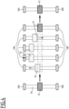
- a first aircraft 10 equipped with a device for assisting the piloting of the aircraft during taxiing 12 according to the invention is illustrated schematically in the Figure 1
- the aircraft taxiing pilot assistance device 12 is preferably located in the cockpit of the aircraft 10.
- the aircraft 10 comprises at least one propulsion engine 14, preferably several propulsion engines 14, capable of generating thrust for the aircraft 10.
- Each propulsion engine 14 is, for example, in particular a jet engine or a turboprop.
- the aircraft 10 further comprises wheels (not visible), at least one braking member 16 associated with each wheel of the main landing gear, for slowing down and stopping the aircraft 10 rolling on the ground, and at least one actuating member 18 of the braking member 16, preferably arranged in the cockpit of the aircraft 10.
- Each propulsion engine 14 and each braking member 16 are each capable of being controlled by the aircraft taxiing pilot assistance device 12, when the aircraft 10 is taxiing on the ground.
- each propulsion engine 14 is capable of being controlled to develop a thrust force on the aircraft 10, increasing or decreasing the mechanical energy of the aircraft 10 while it is taxiing.
- Each braking member 16 is capable of acting on at least one wheel of the aircraft 10, to slow down the rotation of the wheel, for example by friction, and reduce the mechanical energy of the aircraft 10 while it is taxiing.
- the aircraft 10 further comprises at least one sensor for measuring the current taxiing speed and at least one display, preferably located in the cockpit, capable of displaying a taxiing speed value on the basis of the data from the sensor for measuring the current taxiing speed.
- the aircraft 10 further comprises members 20 for modifying the drag of the aircraft.
- These members 20 comprise, for example, air brakes.
- the aircraft piloting assistance device for taxiing 12 comprises at least one control member 30 capable of being actuated by a pilot of the aircraft 10, from a neutral position, to apply an acceleration or deceleration command to the aircraft 10 during taxiing, and a control unit 32, capable of piloting the or each propulsion engine 14 of the aircraft 10 and the or each braking member 16 of the aircraft, as a function of the acceleration or deceleration command during taxiing established by the pilot using the control member 30.
- the aircraft taxiing piloting assistance device 12 further comprises a light display system 34, capable of informing the pilot of the activation of the aircraft taxiing piloting assistance device 12.
- control member 30 is here common with that of a main system for managing the variation of mechanical energy of the aircraft 10 during flight, as described in the French patent application FR3058806 of the Applicant.
- the control unit 32 is then a flight control unit, capable of controlling each propulsion engine 14, and simultaneously each mechanical energy modification member 20, in addition to each braking member 16.
- the aircraft piloting assistance device for taxiing 12 is then capable of switching from an inactive configuration, during takeoff, flight and landing phases of the aircraft 10, and an active configuration, during taxiing.
- control member 30 is capable of being moved by the pilot to establish a mechanical energy variation control of the aircraft 10 intended for the control center 32, so that the control center 32 controls each propulsion engine 14 and each mechanical energy modification member 20, without controlling each braking member 16.
- control member 30 and the control unit 32 in the inactive configuration of the aircraft taxiing pilot assistance device 12 is described in detail in the French patent application FR3058806 . It will not be described in detail further afterwards.
- control member 30 is capable of being moved by the pilot to establish an acceleration or deceleration command for the aircraft 10 during taxiing, intended for the control unit 32, so that the control unit 32 controls each propulsion engine 14 and each braking member 16 in order to apply the acceleration or deceleration command.
- the control member 30 further comprises an active system 46 for applying a force to the movable lever 42, capable of returning the movable lever 42 to a neutral configuration once the desired taxiing speed has been reached and capable of creating respective stops 48A, 48B for maximum acceleration and maximum deceleration (visible on the figures 3 to 8 ), on either side of the travel of the mobile lever 42.
- the control member 30 further comprises at least one button 50 for activating the active configuration of the device for assisting piloting the aircraft during taxiing 12, and at least one button 52 for returning to the inactive configuration of the device for assisting piloting the aircraft during taxiing 12.
- buttons 50, 52 are replaced by one or more buttons, for example located on the guidance panel or on a screen of the aircraft 10.
- an action by the pilot on the actuating member 18 of the braking members 16 also causes the return to the inactive configuration of the aircraft piloting assistance device 12 during taxiing.
- this is also the case when activating another piloting mode of the aircraft, for example a takeoff mode (“TO mode”) or an automatic taxiing mode.
- TO mode takeoff mode
- automatic taxiing mode for example a takeoff mode (“TO mode”) or an automatic taxiing mode.
- the support 40 is suitable for being placed in the cockpit of the aircraft 10, preferably between the cockpit seats, in the central pylon.
- the support 40 comprises an openwork base 54 and an upper cover 56 mounted on the base 54 through which the movable lever 42 is engaged.
- the base 40 defines an interior volume 58 in which a lower part (not visible) of the mobile lever 30 and the active force application system 46 are inserted.
- the upper cover 56 closes the interior volume upwards by defining a longitudinal slide 60 for guiding the movement (in rotation or in translation) of the mobile lever 42.
- the slide 60 advantageously extends parallel to the longitudinal axis of the aircraft 10.
- the movable lever 42 is capable of being moved in the slide 60 relative to a neutral position.
- the movement of the movable lever 42 relative to the neutral position in a first direction (here forward) defines an acceleration command.
- the movement of the movable lever 42 relative to the neutral position in a second direction (here backward), opposite to the first direction, defines a deceleration command.
- the neutral position is fixed.
- the position sensor 44 is capable of measuring information representative of the position of the movable lever 42 in the slide 60, and of transmitting at each instant the representative information to the control unit 32 so that the control unit generates an acceleration or deceleration command for the aircraft 10 acting on each propulsion engine 14 of the aircraft and/or on each braking member 16, as a function of the difference between the current position of the movable lever 42 and the neutral position.
- the active force application system 46 comprises at least one actuator and an actuator control unit, connected to the control unit 32 to control the force applied to the movable lever 42 and the movement of the movable lever 42 in the slide 60.
- the active force application system 46 is for example capable of generating a force opposing the movement of the mobile lever 42 when the pilot grasps the mobile lever 42 and moves it, to oppose resistance to the movement generated by the pilot.
- the active force application system 46 is further capable, once the pilot has released the movable lever 42, of generating a force urging the movable lever 42 returning the movable lever 42 to the neutral position.
- the control unit 32 is capable, depending on the position of the lever 42 in the slide 60, of determining the desired acceleration or deceleration command of the aircraft 10 during taxiing and of controlling each propulsion engine 14 and/or each braking member 16 to apply this command.
- control unit 32 contains a table or a correspondence formula associating with each movement of the lever 42, measured by the position sensor 44, an acceleration or deceleration value to be commanded.
- each movement of the movable lever 42 caused by the pilot away from the neutral position towards the maximum acceleration stop 48A defines an acceleration command which is applied by the control unit 32, producing an increase in speed of the aircraft 10, at the commanded acceleration.
- Each movement of the lever 42 caused by the pilot away from the neutral position towards the maximum deceleration stop 48B defines a deceleration command which is applied by the control unit 32, producing a reduction in speed of the aircraft 10, at the commanded deceleration.
- control unit of the active force application system 46 is capable of determining at each instant during taxiing what is the maximum possible acceleration command of the aircraft 10, taking into account the current speed of the aircraft 10, a predefined maximum speed that the aircraft 10 can reach during taxiing (for example between 30 knots and 50 knots, or between 55 km/h and 92 km/h) and of modifying the position of the maximum acceleration stop 48A applied by the active system force application 46 depending on the maximum possible acceleration command that can be applied.
- the active force application system 46 is capable of moving the movable lever 42 from the current position for controlling the variation in mechanical energy (corresponding to the current thrust applied by each engine 14) to the neutral position when the aircraft piloting assistance device switches to taxiing 12 in the active configuration, and of moving the movable lever 42 to the current position for controlling the variation in mechanical energy (corresponding to the current thrust applied by each engine 14) when the aircraft piloting assistance device switches to taxiing 12 in the inactive configuration.
- the light display system 34 comprises, for example, at least one light strip 70, arranged in the vicinity of the control lever 42, and a control unit 72 of the or each light strip 70, capable of displaying at least one light indication at at least one given point of the light strip 70.
- control unit 72 is for example capable of displaying, on the light strip 70, a first light indication representative of the activation of the aircraft taxiing pilot assistance device 12 (see configuration (b) on the Figure 3 ), a second light indication representative of the current operation of the aircraft pilot assistance device during taxiing 12 (see configuration (c) on the Figure 3 ), and a third light indication representing the deactivation of the aircraft pilot assistance device during taxiing 12 (see configuration (d) on the Figure 3 ).
- the first light indication consists of illuminating a plurality of points of the ramp 70 along the entire length of the slide 60.
- the second light indication consists of illuminating only the position of the stops 48A, 48B and the neutral position.
- the third light indication consists of illuminating lamps of the ramp 70 going from the maximum acceleration stop 48A to the current position of the movable lever 42.
- a method for piloting the aircraft 10 during taxiing by means of the aircraft piloting assistance device 12 will now be described. This method is for example implemented after the aircraft 10 has landed on a landing strip, in particular after an automatic braking system during landing has been deactivated. Alternatively, it is implemented from the aircraft parking point to the takeoff runway.
- the light display system 34 advantageously displays the first light indication (see step (b) on the Figure 3 ).
- the active force application system 16 moves the movable joystick 42 to the neutral position, represented by the dotted square on the Figure 3 .
- the mobile lever 42 therefore remains at rest in this neutral position, which is advantageously marked by local illumination of the ramp 70, according to the second light indication, as illustrated in step (c) of the Figure 3 .
- the movement of the movable lever 42, and the deviation established from the neutral position then defines an acceleration command.
- the control unit 32 receives the representative information coming from the position sensor 44, and determines the acceleration command to be applied. It then controls the or each propulsion motor 14 to achieve the desired acceleration.
- the speed of the aircraft 10 increases progressively following the acceleration set by the command given by the pilot.
- the active force application system 46 returns the movable lever 42 to the neutral position.
- the pilot wishes to apply a deceleration command, as illustrated by the Figure 5 , it moves the movable lever 42 towards the maximum deceleration stop 48B.
- the movement of the lever 42, and the deviation established from the neutral position then defines a deceleration command.
- the control unit 32 receives the representative information coming from the position sensor 44, and determines the deceleration command to be applied.
- the control unit 32 then acts on each braking member 16, and/or on each propulsion motor 14, to achieve the desired deceleration.
- the speed of the aircraft gradually decreases following the deceleration set by the command given by the pilot.
- the active force application system 46 returns the movable lever 42 to the neutral position.
- the maximum acceleration stop 48A remains fixed as long as the acceleration command thus defined remains possible, taking into account the current speed of the aircraft and the predefined maximum speed of the aircraft 10.
- the active force application system 16 determines that the maximum possible acceleration command is decreasing and accordingly moves the maximum acceleration stop 48A toward the neutral position, pushing the movable lever 42 toward the neutral position.
- the maximum acceleration stop 48A prevents the movable joystick 42 from going beyond the neutral position forward.
- the force activation system 46 is capable of defining a maximum deceleration stop 48B which can be crossed by the pilot, and a notch 80 located beyond the maximum deceleration stop 48B.
- the pilot crosses the maximum deceleration stop 48B, and places the movable lever 42 in the notch 80, the movable lever 42 remains held in the notch 80, even if the pilot releases the movable lever 42, until the aircraft stops.
- the neutral position is a fixed neutral position. It corresponds to a fixed point of the slide 60, for example located in the middle of the slide 60.
- the neutral position is a movable neutral position which moves along the slide 60 depending on the current speed of the aircraft and the maximum possible speed during taxiing predefined for the aircraft 10.
- the mobile neutral position between the maximum acceleration stop 48A and the maximum deceleration stop 48B gives an indication of the current speed level in the authorized taxiing speed interval [0; 50] knots, i.e. between 0 km/h and 93 km/h.
- the active force application system 46 controls the mobile lever 42 to the mobile neutral position, even in the absence of action by the pilot on the mobile lever 42.
- the acceleration command defined by the pilot relative to the mobile neutral position causes the control unit 32 to accelerate the aircraft 10 while maintaining the desired acceleration command, which increases the speed of the aircraft 10.
- the mobile neutral position therefore gradually approaches the maximum acceleration stop 48A, since the current speed of the aircraft increases.
- the mobile neutral position to which the mobile lever 42 is returned therefore gives the pilot an immediate visual indication of the value of the current speed in relation to the authorized speed interval.
- control unit 32 of the aircraft taxiing pilot assistance device 12 in the active configuration pilots each engine 14 in its nominal thrust mode, advantageously without using the reverse thrust mode.
- the reverse thrust mode could be used.
- the accelerations and decelerations commanded by the pilot are controlled, which produces a very positive impact on the comfort of the passengers, by avoiding the acceleration or deceleration jolts which occur when the pilot has difficulty reaching the speed he wishes to apply.
- the aircraft 10 is devoid of an electric motor capable of driving a wheel of the aircraft, independently of the propulsion motors 14 generating thrust for the aircraft. This lightens the aircraft, simplifies its maintenance and limits the risk of breakdowns.
- the aircraft 10 is equipped with at least one electric motor capable of driving a wheel of the aircraft, independently of the propulsion motors 14 generating thrust of the aircraft.
- the aircraft taxiing piloting assistance device 12 is then capable of controlling the electric motor and/or each braking member 16 to apply the acceleration or deceleration command defined by the control member 30, and not a speed instruction, which improves passenger comfort.
- control member 30 of the aircraft taxiing piloting assistance device 12 is an additional control member relative to the control member control of the variation of mechanical energy of the aircraft used during takeoff, flight and landing.
- control member 30 does not have a mobile joystick. It comprises, for example, hardware or software acceleration and deceleration buttons which make it possible to control a movement of a cursor relative to a neutral position.
- a display represents a gauge with the cursor, the neutral position, as well as the maximum acceleration and minimum deceleration stops.
Landscapes
- Engineering & Computer Science (AREA)
- Aviation & Aerospace Engineering (AREA)
- Automation & Control Theory (AREA)
- Radar, Positioning & Navigation (AREA)
- Remote Sensing (AREA)
- Physics & Mathematics (AREA)
- General Physics & Mathematics (AREA)
- Mechanical Engineering (AREA)
- Regulating Braking Force (AREA)
- Tires In General (AREA)
- Control Of Velocity Or Acceleration (AREA)
- Toys (AREA)
Claims (14)
- Vorrichtung (12) zur Steuerhilfe eines Luftfahrzeugs (10) beim Rollen, umfassend:- ein Steuerelement (30), das geeignet ist, um von einem Piloten ausgehend von einer Neutralstellung betätigt zu werden, um einen Steuerbefehl zum Rollen zu definieren, um die Geschwindigkeit des Luftfahrzeugs (10) zu steuern;- eine Flugsteuerzentrale (32), die geeignet ist, um den oder jeden Motor (14) zum Antrieb des Luftfahrzeugs zu steuern, um den von dem Piloten definierten Steuerbefehl zum Rollen anzuwenden;der Steuerbefehl zum Rollen ein Befehl zur Beschleunigung oder Verzögerung des Luftfahrzeugs (10) beim Rollen ist, und das Steuerelement (30) geeignet ist, um bis zu einem Anschlag für maximale Beschleunigung (48A) und bis zu einem Anschlag für minimale Verzögerung (48B) bewegt zu werden.
- Vorrichtung (12) zur Steuerhilfe eines Luftfahrzeugs (10) beim Rollen nach Anspruch 1, wobei die Steuerzentrale geeignet ist, um zusätzlich mindestens ein Bremselement (16) des Luftfahrzeugs (10) anzusteuern, um den von dem Piloten definierten Beschleunigungs- oder Verzögerungsbefehl anzuwenden.
- Vorrichtung (12) zur Steuerhilfe eines Luftfahrzeugs (10) beim Rollen nach Anspruch 1 oder 2, wobei nach Anwenden des Beschleunigungs- oder Verzögerungsbefehls und dem Loslassen des Steuerelements (30) das Steuerelement (30) automatisch in die Neutralstellung zurückgeführt wird.
- Vorrichtung (12) zur Steuerhilfe eines Luftfahrzeugs (10) beim Rollen nach Anspruch 3, wobei die Neutralstellung eine feste Neutralstellung in Bezug auf einen Hub des Steuerelements (30) ist, wobei das Steuerelement (30) automatisch in die feste Neutralstellung zurückgeführt wird.
- Vorrichtung (12) zur Steuerhilfe eines Luftfahrzeugs (10) beim Rollen nach Anspruch 3, wobei die Neutralstellung eine bewegliche Neutralstellung in Bezug auf einen Hub des Steuerelements (30) ist, wobei das Steuerelement (30) automatisch in die bewegliche Neutralstellung zurückgeführt wird, wobei sich die bewegliche Neutralstellung in Richtung der aktuellen Position des Steuerelements (30) bewegen kann.
- Vorrichtung (12) zur Steuerhilfe eines Luftfahrzeugs (10) beim Rollen nach einem der vorherigen Ansprüche, wobei der Anschlag für maximale Beschleunigung (48A) geeignet ist, um sich entlang des Wegs des Steuerelements (30) zu bewegen, um den Weg des Steuerelements (30) abhängig von der aktuellen Geschwindigkeit des Luftfahrzeugs zu begrenzen.
- Vorrichtung (12) zur Steuerhilfe eines Luftfahrzeugs (10) beim Rollen nach einem der vorherigen Ansprüche, wobei der Anschlag für minimale Verzögerung (48B) überwunden werden kann, um eine Raste (80) für maximale Beschleunigung zu erreichen, in der das Steuerelement (30) in seiner Position blockiert ist.
- Vorrichtung (12) zur Steuerhilfe eines Luftfahrzeugs (10) beim Rollen nach einem der vorherigen Ansprüche, wobei der Motor (14) ein Strahltriebwerk oder ein Turboprop-Triebwerk ist, das geeignet ist, um eine Schubkraft auf das Luftfahrzeug auszuüben.
- Vorrichtung (12) zur Steuerhilfe eines Luftfahrzeugs (10) beim Rollen nach Anspruch 8, wobei das Steuerelement (30) einen beweglichen Hebel (42) zum Steuern mindestens eines Motors (14) des Luftfahrzeugs (10), der eine Schubkraft ausüben kann, und/oder zum Steuern eines Elements (20) zur Veränderung der Schubumkehr des Luftfahrzeugs (10) umfasst, das geeignet ist, um die mechanische Energie des Luftfahrzeugs zu reduzieren, die Vorrichtung zur Steuerhilfe des Luftfahrzeugs beim Rollen (12) geeignet ist, um zwischen einer inaktiven Konfiguration während der Start-, Flug- und Landephasen und einer aktiven Konfiguration beim Rollen umzuschalten.
- Vorrichtung (12) zur Steuerhilfe eines Luftfahrzeugs (10) beim Rollen nach Anspruch 9, wobei das Steuerelement (30) in der inaktiven Konfiguration der Vorrichtung zur Steuerhilfe des Luftfahrzeugs beim Rollen (12) geeignet ist, um von dem Piloten verschoben zu werden, um einen für die Steuerzentrale (32) bestimmten Befehl zur Veränderung der mechanischen Energie des Luftfahrzeugs (10) zu erstellen, damit die Steuerzentrale (32) den oder jeden Antriebsmotor (14) und das oder jedes Element zur Veränderung des Luftwiderstands (20) steuert, ohne das Bremselement (16) des Luftfahrzeugs (10) zu steuern,
und wobei das Steuerelement (30) in der aktiven Konfiguration der Vorrichtung zur Steuerhilfe des Luftfahrzeugs beim Rollen (12) geeignet ist, um durch den Piloten bewegt zu werden, um einen Beschleunigungs- oder Verzögerungsbefehl beim Rollen des Luftfahrzeugs (10) zu erstellen, der für die Steuerzentrale (32) bestimmt ist, damit die Steuerzentrale (32) jeden Antriebsmotor (14) und optional mindestens ein Bremselement (16) steuert. - Vorrichtung (12) zur Steuerhilfe eines Luftfahrzeugs (10) beim Rollen nach Anspruch 9 oder 10, umfassend einen Knopf (50) zum Aktivieren der Vorrichtung zur Steuerhilfe des Luftfahrzeugs beim Rollen (12), der geeignet ist, um die Vorrichtung zur Steuerhilfe des Luftfahrzeugs beim Rollen (12) in die aktive Konfiguration zu überführen, wobei der Aktivierungsknopf (50) vorteilhafterweise auf dem beweglichen Hebel (42) angeordnet ist, wobei die Vorrichtung (12) optional einen Knopf (52) zur Deaktivierung der Vorrichtung zur Steuerhilfe des Luftfahrzeugs beim Rollen (12) umfasst, der geeignet ist, um die Vorrichtung (12) zur Steuerhilfe beim Rollen in die inaktive Konfiguration zu überführen, wobei der Deaktivierungsknopf (52) vorteilhafterweise auf dem beweglichen Hebel (42) angeordnet ist.
- Vorrichtung (12) zur Steuerhilfe eines Luftfahrzeugs (10) beim Rollen nach einem der Ansprüche 10 bis 11, umfassend ein Leuchtanzeigesystem (34), das geeignet ist, um mindestens einen Leuchtindikator für die Aktivierung, den Betrieb oder/und die Deaktivierung der Vorrichtung zur Steuerhilfe des Luftfahrzeugs beim Rollen (12) zu erzeugen.
- Luftfahrzeug (10), umfassend eine Vorrichtung (12) zur Steuerhilfe eines Luftfahrzeugs (10) beim Rollen nach einem der vorherigen Ansprüche, wobei mindestens ein Antriebsmotor (14) geeignet ist, um von der Flugsteuerungszentrale (32) gesteuert zu werden, um den von dem Steuerelement (30) festgelegten Beschleunigungs- oder Verzögerungsbefehl anzuwenden, das Luftfahrzeug (10) umfassend mindestens ein Bremselement (16), das optional geeignet ist, um auch von der Flugsteuerungszentrale (32) gesteuert zu werden, um den vom Steuerelement (30) festgelegten Beschleunigungs- oder Verzögerungsbefehl anzuwenden.
- Verfahren zum Steuern des Rollens eines Luftfahrzeugs (10), das mittels einer Vorrichtung (12) zur Steuerhilfe eines Luftfahrzeugs (10) beim Rollen durchgeführt wird, das Verfahren umfassend die folgenden Schritte:- Betätigen, durch einen Piloten, eines Steuerelements (30) der Vorrichtung (12) zur Steuerhilfe des Luftfahrzeugs beim Rollen ausgehend von einer Neutralstellung, um einen Steuerbefehl beim Rollen zu erstellen;- Ansteuern eines oder jedes Antriebsmotors (14) des Luftfahrzeugs (10) durch eine Flugsteuerzentrale (32) der Vorrichtung (12) zur Steuerhilfe des Luftfahrzeugs beim Rollen, um den von dem Piloten definierten Steuerbefehl beim Rollen anzuwenden,wobei der Steuerbefehl beim Rollen ein Beschleunigungs- oder Verzögerungsbefehl des Luftfahrzeugs (10) ist, und wobei das Steuerelement (30) zum Erstellen des Steuerbefehls beim Rollen geeignet ist, um durch den Piloten bis zu einem Anschlag für maximale Beschleunigung (48A) und bis zu einem Anschlag für minimale Verzögerung (48B) bewegt zu werden,wobei die Steuerzentrale (32) ferner optional mindestens ein Bremselement (16) des Luftfahrzeugs (10) ansteuert, um den von dem Piloten definierten Beschleunigungs- oder Verzögerungsbefehl anzuwenden.
Applications Claiming Priority (1)
| Application Number | Priority Date | Filing Date | Title |
|---|---|---|---|
| FR2108070A FR3125606B1 (fr) | 2021-07-26 | 2021-07-26 | Dispositif d'aide au pilotage en accélération d'un aéronef au taxiage en vue de contrôler sa vitesse, aéronef et procédés associés |
Publications (2)
| Publication Number | Publication Date |
|---|---|
| EP4124570A1 EP4124570A1 (de) | 2023-02-01 |
| EP4124570B1 true EP4124570B1 (de) | 2025-04-16 |
Family
ID=78536311
Family Applications (1)
| Application Number | Title | Priority Date | Filing Date |
|---|---|---|---|
| EP22186839.1A Active EP4124570B1 (de) | 2021-07-26 | 2022-07-26 | Vorrichtung zur unterstützung des beschleunigenden pilotierens eines rollenden flugzeugs zur steuerung seiner geschwindigkeit, flugzeug und zugehörige verfahren |
Country Status (6)
| Country | Link |
|---|---|
| US (1) | US12084192B2 (de) |
| EP (1) | EP4124570B1 (de) |
| BR (1) | BR102022014629A2 (de) |
| CA (1) | CA3168180A1 (de) |
| ES (1) | ES3032242T3 (de) |
| FR (1) | FR3125606B1 (de) |
Families Citing this family (3)
| Publication number | Priority date | Publication date | Assignee | Title |
|---|---|---|---|---|
| GB2617326A (en) * | 2022-03-31 | 2023-10-11 | Airbus Operations Ltd | Aircraft nose landing gear assembly |
| US12503224B2 (en) | 2024-01-08 | 2025-12-23 | Lockheed Martin Corporation | Thrust control for ground navigation of aerial vehicles |
| US20260071580A1 (en) * | 2024-09-10 | 2026-03-12 | General Electric Company | Turbine engine control system |
Family Cites Families (15)
| Publication number | Priority date | Publication date | Assignee | Title |
|---|---|---|---|---|
| US7980509B2 (en) * | 2007-03-08 | 2011-07-19 | The Ashman Group, Llc | Aircraft taxiing systems |
| FR2929019A1 (fr) | 2008-03-18 | 2009-09-25 | Airbus France Sas | Procede et dispositif de pilotage lateral d'un aeronef roulant au sol. |
| FR2944775B1 (fr) * | 2009-04-24 | 2013-03-08 | Messier Bugatti | Procede de deplacement d'un aeronef au sol |
| FR2960520B1 (fr) * | 2010-05-26 | 2012-06-29 | Airbus Operations Sas | Aeronef comprenant un moteur de train |
| FR2968111B1 (fr) | 2010-11-30 | 2014-08-29 | Airbus Operations Sas | Procede et systeme d'aide au pilotage d'un aeronef roulant au sol sur un domaine aeroportuaire. |
| US9676475B2 (en) * | 2011-09-02 | 2017-06-13 | Borealis Technical Limited | System and method for maintaining aircraft ground travel speed and direction |
| US8620493B2 (en) | 2012-05-03 | 2013-12-31 | Honeywell International Inc. | Electric taxi auto-guidance and control system |
| US9457896B2 (en) | 2014-01-24 | 2016-10-04 | Honeywell International Inc. | Electric taxi system with speed control (ETSSC) |
| FR3022340B1 (fr) | 2014-06-16 | 2016-07-15 | Thales Sa | Procede et dispositif de determination d'une consigne de controle d'un aeronef, produit programme d'ordinateur et aeronef associes |
| US20170032687A1 (en) | 2015-07-31 | 2017-02-02 | Honeywell International Inc. | Automatic in/out aircraft taxiing, terminal gate locator and aircraft positioning |
| FR3044153B1 (fr) | 2015-11-19 | 2017-11-10 | Airbus | Procede de pilotage automatique d'un aeronef au sol et dispositif pour sa mise en oeuvre |
| US9862499B2 (en) | 2016-04-25 | 2018-01-09 | Airbus Operations (S.A.S.) | Human machine interface for displaying information relative to the energy of an aircraft |
| FR3058806B1 (fr) | 2016-11-14 | 2019-01-25 | Dassault Aviation | Dispositif de gestion de l'energie mecanique d'un aeronef, presentant un systeme d'application de force sur une manette de commande, aeronef et procede associes |
| FR3090915B1 (fr) * | 2018-12-19 | 2021-01-22 | Safran Landing Systems | Dispositif de motorisation d’un train d’atterrissage |
| CN111516887A (zh) | 2020-04-30 | 2020-08-11 | 中国商用飞机有限责任公司 | 自动滑行系统、供电系统、飞行器及供电方法 |
-
2021
- 2021-07-26 FR FR2108070A patent/FR3125606B1/fr active Active
-
2022
- 2022-07-19 CA CA3168180A patent/CA3168180A1/fr active Pending
- 2022-07-25 BR BR102022014629-2A patent/BR102022014629A2/pt unknown
- 2022-07-25 US US17/872,628 patent/US12084192B2/en active Active
- 2022-07-26 ES ES22186839T patent/ES3032242T3/es active Active
- 2022-07-26 EP EP22186839.1A patent/EP4124570B1/de active Active
Also Published As
| Publication number | Publication date |
|---|---|
| FR3125606B1 (fr) | 2024-01-19 |
| CA3168180A1 (fr) | 2023-01-26 |
| US20230025868A1 (en) | 2023-01-26 |
| BR102022014629A2 (pt) | 2023-03-07 |
| EP4124570A1 (de) | 2023-02-01 |
| US12084192B2 (en) | 2024-09-10 |
| FR3125606A1 (fr) | 2023-01-27 |
| ES3032242T3 (en) | 2025-07-16 |
Similar Documents
| Publication | Publication Date | Title |
|---|---|---|
| EP4124570B1 (de) | Vorrichtung zur unterstützung des beschleunigenden pilotierens eines rollenden flugzeugs zur steuerung seiner geschwindigkeit, flugzeug und zugehörige verfahren | |
| EP2805887B1 (de) | System und Verfahren zur Steuerung eines Luftfahrzeuges | |
| CA2983993C (fr) | Dispositif de gestion de l'energie mecanique d'un aeronef, presentant un systeme d'application de force sur une manette de commande, aeronef et procede associes | |
| EP1031453B1 (de) | Fahrpedal für ein Kraftfahrzeug | |
| EP2514647B1 (de) | Kontrollverfahren der Bremswirkung am Boden eines Fahrzeugs | |
| CA2983999A1 (fr) | Dispositif de gestion de l'energie mecanique d'un aeronef, presentant un systeme auxiliaire de gestion d'energie, aeronef et procede associes | |
| FR3024126A1 (fr) | Systeme de controle d'un aeronef | |
| FR3022340A1 (fr) | Procede et dispositif de determination d'une consigne de controle d'un aeronef, produit programme d'ordinateur et aeronef associes | |
| EP3271244B1 (de) | Vorrichtung zur flugsteuerung eines luftfahrzeugs | |
| EP4124567B1 (de) | Vorrichtung zur unterstützung des steuerns eines flugzeugs bei taxi, unter verwendung von mindestens einem motor und mindestens einem bremsteil, flugzeug und zugehöriges verfahren | |
| FR3017367A1 (fr) | Aeronef comportant un train d'atterrissage dont une roue est pourvue d'un moteur electrique et un systeme de commande dudit moteur electrique | |
| FR3072650A1 (fr) | Systeme de controle d'une trajectoire laterale d'un aeronef au sol | |
| CA3065871C (fr) | Dispositif de commande de la motorisation d'un train d'atterrissage | |
| EP4085187B1 (de) | System zur steuerung von schubumkehrmitteln eines flugzeuges | |
| EP3251945B1 (de) | Verfahren zur optimierung der startparameter eines luftfahrzeugs | |
| CA2983953A1 (fr) | Dispositif de gestion de l'energie mecanique d'un aeronef, presentant un systeme lumineux, aeronef et procede associes | |
| EP3034389B1 (de) | Marineplattform, die mit einer flugzone ausgestattet ist, insbesondere für den einsatz einer drohne | |
| EP0306355B1 (de) | Verbundene automatische Regelung der Trimmung und Leistung für die allgemeine Handels- und Geschäftsluftfahrt | |
| FR2570672A1 (fr) | Double systeme de commandes automatiques de compensateur et de puissance pour l'aviation generale, commerciale et d'affaires | |
| FR3125139A1 (fr) | Dispositif de commande d'un organe de variation d'énergie mécanique d'un aéronef et procédé associé | |
| FR2619353A2 (fr) | Double systeme de commande automatique de compensateur et de puissance pour l'aviation generale, commerciale et d'affaires | |
| EP1031454A1 (de) | Einrichtung zur Aktivierung einer Geschwindigkeitsregelanlage für ein Kraftfahrzeug |
Legal Events
| Date | Code | Title | Description |
|---|---|---|---|
| PUAI | Public reference made under article 153(3) epc to a published international application that has entered the european phase |
Free format text: ORIGINAL CODE: 0009012 |
|
| STAA | Information on the status of an ep patent application or granted ep patent |
Free format text: STATUS: THE APPLICATION HAS BEEN PUBLISHED |
|
| AK | Designated contracting states |
Kind code of ref document: A1 Designated state(s): AL AT BE BG CH CY CZ DE DK EE ES FI FR GB GR HR HU IE IS IT LI LT LU LV MC MK MT NL NO PL PT RO RS SE SI SK SM TR |
|
| STAA | Information on the status of an ep patent application or granted ep patent |
Free format text: STATUS: REQUEST FOR EXAMINATION WAS MADE |
|
| 17P | Request for examination filed |
Effective date: 20230630 |
|
| RBV | Designated contracting states (corrected) |
Designated state(s): AL AT BE BG CH CY CZ DE DK EE ES FI FR GB GR HR HU IE IS IT LI LT LU LV MC MK MT NL NO PL PT RO RS SE SI SK SM TR |
|
| STAA | Information on the status of an ep patent application or granted ep patent |
Free format text: STATUS: EXAMINATION IS IN PROGRESS |
|
| 17Q | First examination report despatched |
Effective date: 20230928 |
|
| GRAP | Despatch of communication of intention to grant a patent |
Free format text: ORIGINAL CODE: EPIDOSNIGR1 |
|
| STAA | Information on the status of an ep patent application or granted ep patent |
Free format text: STATUS: GRANT OF PATENT IS INTENDED |
|
| GRAJ | Information related to disapproval of communication of intention to grant by the applicant or resumption of examination proceedings by the epo deleted |
Free format text: ORIGINAL CODE: EPIDOSDIGR1 |
|
| STAA | Information on the status of an ep patent application or granted ep patent |
Free format text: STATUS: EXAMINATION IS IN PROGRESS |
|
| INTG | Intention to grant announced |
Effective date: 20241112 |
|
| INTC | Intention to grant announced (deleted) | ||
| GRAP | Despatch of communication of intention to grant a patent |
Free format text: ORIGINAL CODE: EPIDOSNIGR1 |
|
| STAA | Information on the status of an ep patent application or granted ep patent |
Free format text: STATUS: GRANT OF PATENT IS INTENDED |
|
| INTG | Intention to grant announced |
Effective date: 20250127 |
|
| GRAS | Grant fee paid |
Free format text: ORIGINAL CODE: EPIDOSNIGR3 |
|
| GRAA | (expected) grant |
Free format text: ORIGINAL CODE: 0009210 |
|
| STAA | Information on the status of an ep patent application or granted ep patent |
Free format text: STATUS: THE PATENT HAS BEEN GRANTED |
|
| AK | Designated contracting states |
Kind code of ref document: B1 Designated state(s): AL AT BE BG CH CY CZ DE DK EE ES FI FR GB GR HR HU IE IS IT LI LT LU LV MC MK MT NL NO PL PT RO RS SE SI SK SM TR |
|
| REG | Reference to a national code |
Ref country code: GB Ref legal event code: FG4D Free format text: NOT ENGLISH |
|
| REG | Reference to a national code |
Ref country code: CH Ref legal event code: EP Ref country code: DE Ref legal event code: R096 Ref document number: 602022013149 Country of ref document: DE |
|
| REG | Reference to a national code |
Ref country code: IE Ref legal event code: FG4D Free format text: LANGUAGE OF EP DOCUMENT: FRENCH |
|
| REG | Reference to a national code |
Ref country code: SE Ref legal event code: TRGR |
|
| REG | Reference to a national code |
Ref country code: ES Ref legal event code: FG2A Ref document number: 3032242 Country of ref document: ES Kind code of ref document: T3 Effective date: 20250716 |
|
| PGFP | Annual fee paid to national office [announced via postgrant information from national office to epo] |
Ref country code: FR Payment date: 20250616 Year of fee payment: 4 |
|
| REG | Reference to a national code |
Ref country code: NL Ref legal event code: MP Effective date: 20250416 |
|
| PG25 | Lapsed in a contracting state [announced via postgrant information from national office to epo] |
Ref country code: NL Free format text: LAPSE BECAUSE OF FAILURE TO SUBMIT A TRANSLATION OF THE DESCRIPTION OR TO PAY THE FEE WITHIN THE PRESCRIBED TIME-LIMIT Effective date: 20250416 |
|
| REG | Reference to a national code |
Ref country code: AT Ref legal event code: MK05 Ref document number: 1785469 Country of ref document: AT Kind code of ref document: T Effective date: 20250416 |
|
| PG25 | Lapsed in a contracting state [announced via postgrant information from national office to epo] |
Ref country code: PT Free format text: LAPSE BECAUSE OF FAILURE TO SUBMIT A TRANSLATION OF THE DESCRIPTION OR TO PAY THE FEE WITHIN THE PRESCRIBED TIME-LIMIT Effective date: 20250818 Ref country code: FI Free format text: LAPSE BECAUSE OF FAILURE TO SUBMIT A TRANSLATION OF THE DESCRIPTION OR TO PAY THE FEE WITHIN THE PRESCRIBED TIME-LIMIT Effective date: 20250416 |
|
| PGFP | Annual fee paid to national office [announced via postgrant information from national office to epo] |
Ref country code: ES Payment date: 20250811 Year of fee payment: 4 |
|
| PGFP | Annual fee paid to national office [announced via postgrant information from national office to epo] |
Ref country code: DE Payment date: 20250711 Year of fee payment: 4 |
|
| REG | Reference to a national code |
Ref country code: LT Ref legal event code: MG9D |
|
| PG25 | Lapsed in a contracting state [announced via postgrant information from national office to epo] |
Ref country code: NO Free format text: LAPSE BECAUSE OF FAILURE TO SUBMIT A TRANSLATION OF THE DESCRIPTION OR TO PAY THE FEE WITHIN THE PRESCRIBED TIME-LIMIT Effective date: 20250716 Ref country code: GR Free format text: LAPSE BECAUSE OF FAILURE TO SUBMIT A TRANSLATION OF THE DESCRIPTION OR TO PAY THE FEE WITHIN THE PRESCRIBED TIME-LIMIT Effective date: 20250717 |
|
| PG25 | Lapsed in a contracting state [announced via postgrant information from national office to epo] |
Ref country code: PL Free format text: LAPSE BECAUSE OF FAILURE TO SUBMIT A TRANSLATION OF THE DESCRIPTION OR TO PAY THE FEE WITHIN THE PRESCRIBED TIME-LIMIT Effective date: 20250416 |
|
| PG25 | Lapsed in a contracting state [announced via postgrant information from national office to epo] |
Ref country code: BG Free format text: LAPSE BECAUSE OF FAILURE TO SUBMIT A TRANSLATION OF THE DESCRIPTION OR TO PAY THE FEE WITHIN THE PRESCRIBED TIME-LIMIT Effective date: 20250416 |
|
| PG25 | Lapsed in a contracting state [announced via postgrant information from national office to epo] |
Ref country code: HR Free format text: LAPSE BECAUSE OF FAILURE TO SUBMIT A TRANSLATION OF THE DESCRIPTION OR TO PAY THE FEE WITHIN THE PRESCRIBED TIME-LIMIT Effective date: 20250416 |
|
| PG25 | Lapsed in a contracting state [announced via postgrant information from national office to epo] |
Ref country code: AT Free format text: LAPSE BECAUSE OF FAILURE TO SUBMIT A TRANSLATION OF THE DESCRIPTION OR TO PAY THE FEE WITHIN THE PRESCRIBED TIME-LIMIT Effective date: 20250416 |
|
| PGFP | Annual fee paid to national office [announced via postgrant information from national office to epo] |
Ref country code: SE Payment date: 20250729 Year of fee payment: 4 |
|
| PG25 | Lapsed in a contracting state [announced via postgrant information from national office to epo] |
Ref country code: RS Free format text: LAPSE BECAUSE OF FAILURE TO SUBMIT A TRANSLATION OF THE DESCRIPTION OR TO PAY THE FEE WITHIN THE PRESCRIBED TIME-LIMIT Effective date: 20250716 |
|
| PGFP | Annual fee paid to national office [announced via postgrant information from national office to epo] |
Ref country code: CZ Payment date: 20250725 Year of fee payment: 4 |
|
| PG25 | Lapsed in a contracting state [announced via postgrant information from national office to epo] |
Ref country code: IS Free format text: LAPSE BECAUSE OF FAILURE TO SUBMIT A TRANSLATION OF THE DESCRIPTION OR TO PAY THE FEE WITHIN THE PRESCRIBED TIME-LIMIT Effective date: 20250816 |
|
| PG25 | Lapsed in a contracting state [announced via postgrant information from national office to epo] |
Ref country code: LV Free format text: LAPSE BECAUSE OF FAILURE TO SUBMIT A TRANSLATION OF THE DESCRIPTION OR TO PAY THE FEE WITHIN THE PRESCRIBED TIME-LIMIT Effective date: 20250416 |
|
| PG25 | Lapsed in a contracting state [announced via postgrant information from national office to epo] |
Ref country code: DK Free format text: LAPSE BECAUSE OF FAILURE TO SUBMIT A TRANSLATION OF THE DESCRIPTION OR TO PAY THE FEE WITHIN THE PRESCRIBED TIME-LIMIT Effective date: 20250416 Ref country code: SM Free format text: LAPSE BECAUSE OF FAILURE TO SUBMIT A TRANSLATION OF THE DESCRIPTION OR TO PAY THE FEE WITHIN THE PRESCRIBED TIME-LIMIT Effective date: 20250416 |
|
| REG | Reference to a national code |
Ref country code: DE Ref legal event code: R097 Ref document number: 602022013149 Country of ref document: DE |
|
| PG25 | Lapsed in a contracting state [announced via postgrant information from national office to epo] |
Ref country code: EE Free format text: LAPSE BECAUSE OF FAILURE TO SUBMIT A TRANSLATION OF THE DESCRIPTION OR TO PAY THE FEE WITHIN THE PRESCRIBED TIME-LIMIT Effective date: 20250416 |
|
| PG25 | Lapsed in a contracting state [announced via postgrant information from national office to epo] |
Ref country code: SK Free format text: LAPSE BECAUSE OF FAILURE TO SUBMIT A TRANSLATION OF THE DESCRIPTION OR TO PAY THE FEE WITHIN THE PRESCRIBED TIME-LIMIT Effective date: 20250416 |
|
| PG25 | Lapsed in a contracting state [announced via postgrant information from national office to epo] |
Ref country code: IT Free format text: LAPSE BECAUSE OF FAILURE TO SUBMIT A TRANSLATION OF THE DESCRIPTION OR TO PAY THE FEE WITHIN THE PRESCRIBED TIME-LIMIT Effective date: 20250416 |
|
| PG25 | Lapsed in a contracting state [announced via postgrant information from national office to epo] |
Ref country code: RO Free format text: LAPSE BECAUSE OF FAILURE TO SUBMIT A TRANSLATION OF THE DESCRIPTION OR TO PAY THE FEE WITHIN THE PRESCRIBED TIME-LIMIT Effective date: 20250416 |
|
| PLBE | No opposition filed within time limit |
Free format text: ORIGINAL CODE: 0009261 |
|
| STAA | Information on the status of an ep patent application or granted ep patent |
Free format text: STATUS: NO OPPOSITION FILED WITHIN TIME LIMIT |
|
| REG | Reference to a national code |
Ref country code: CH Ref legal event code: H13 Free format text: ST27 STATUS EVENT CODE: U-0-0-H10-H13 (AS PROVIDED BY THE NATIONAL OFFICE) Effective date: 20260224 |
|
| REG | Reference to a national code |
Ref country code: CH Ref legal event code: L10 Free format text: ST27 STATUS EVENT CODE: U-0-0-L10-L00 (AS PROVIDED BY THE NATIONAL OFFICE) Effective date: 20260225 |
|
| PG25 | Lapsed in a contracting state [announced via postgrant information from national office to epo] |
Ref country code: LU Free format text: LAPSE BECAUSE OF NON-PAYMENT OF DUE FEES Effective date: 20250726 |
|
| 26N | No opposition filed |
Effective date: 20260119 |
|
| REG | Reference to a national code |
Ref country code: BE Ref legal event code: MM Effective date: 20250731 |
|
| PG25 | Lapsed in a contracting state [announced via postgrant information from national office to epo] |
Ref country code: BE Free format text: LAPSE BECAUSE OF NON-PAYMENT OF DUE FEES Effective date: 20250731 |
|
| PG25 | Lapsed in a contracting state [announced via postgrant information from national office to epo] |
Ref country code: CH Free format text: LAPSE BECAUSE OF NON-PAYMENT OF DUE FEES Effective date: 20250731 |